
Abstract
This article discusses the problem of usability of the USB 2.0 protocol in the area of real-time control of a mobile robot. Optimization methods of data transfer handling were proposed. The impact of the optimization results on the entire system's performance was examined in practice. As a test-bed, a hybrid system composed of two devices communicating by direct USB connection was implemented. The first of the mentioned devices was a 32-bit SoC micro-system serving as a direct control unit, and the second one was an off-the-shelf PDA providing supervisory control and logging. Due to this design, the system meets regimes of the real-time constraints and maintains continuity of a data stream at a large bandwidth. The real-time performances of subsystems and the entire system were experimentally examined depending on various operating conditions. Thanks to the performed experiments, the dependency of real-time limits on operational parameters has been determined.
1. Introduction
1.1 Motivation
The tablets of today have been especially designed for wireless network communication. It is therefore quite common to see a tablet (personal digital assistance - PDA) in the hands of an operator, for example a remotely operated vehicle (ROV). In this case, the PDA plays a role of a user interface and sends simple operator commands via Bluetooth or WiFi. Could such an off-the-shelf PDA serve as on-board computer of the ROV mentioned, or other kinds of a mobile robot? This question has motivated the author's practical experiments, the results of which are presented in this paper.
The construction of a control system for mobile robots is a complex multi-aspect process and requires consideration of various factors. The main technical problems are real-time performance, substantial hardware and software complexity. On the other hand there are economical problems, such as the necessity to shorten the time needed for its design and implementation. Since such systems are realized in small production batches, the share of the designing costs is very large. Using the standard off-the-shelf software components can eliminate the need for the specialized knowledge of the operating system used.
The control system of mobile robots belongs to the category of hard real-time systems. Following the Oxford Dictionary of Computing hard real-time systems can be defined as ‘those in which it is absolutely imperative that each and every response time (to externally generated stimuli) requirement be met’. For mobile robot control systems the tasks of measurement, calculation and setting of control actuators are to be performed at specific, predefined periods of time, which can be regarded as deadlines. In general, real-time systems are divided into hard real-time systems and soft real-time systems. In the case of the latter, exceeding the operational deadlines is not a critical error.
The control system for the robot usually consists of two main parts:
Direct control subsystem (DCS). This comprises acquisition modules (multichannel AD converters, quadrature encoders, digital inputs), PID controllers and actuator output modules (DA converters, PWM, digital outputs). The required control loop time response is 1 ms or less and DCS is the hard real-time part. Supervisory control subsystem (SCS). This can include the trajectory-planning module and a sophisticated type of control algorithm such as a multidimensional generalized predictive controller (GPC) or a model predictive controller (MPC). SCS cooperates with the DCS part and forms an outer control loop. SCS runs in the soft real-time, but the required control loop time response is slower than that of DCS, e.g., 5–10 ms. SCS should include user interfaces. The continuous data stream logging module is also very important because SCS should back up the data from the sensors and operational data from DCS.
Despite the mentioned network communication ability, the off-the-shelf PDAs are small in size, their power consumption is low, and they are shock resistant by design. PDA devices possess built-in cameras and GPS. Wireless communication can be easily programmed thanks to standard communication libraries for the WiFi or Bluetooth devices. SD/microSD cards can be used for storing large amounts of data. A subclass of the tablet devices equipped with Windows CE family is of special interest because of the way of interrupt servicing by the Windows CE kernel. In short, the Windows CE kernel guarantees that an interruption will be serviced within a specified amount of time. Furthermore, the worst case latency for an interrupt can be calculated by summation of interrupt service routine latency and interrupt service thread latency. This concerns interrupts from USB devices too. To summarize, all of these features of the PDAs are suitable for a mobile robot control. Thus, an application of the off-the-shelf PDA device for supervisory control subsystem (SCS) is proposed. One of many advantages of such an approach is a possibility of performing a substantial part of the programming work by computer programmers, who do not have the specialized knowledge of the hardware. An example of a methodology for rapid prototyping of such systems is shown in [1].
However, standard purchasable PDAs are not equipped with typical SPI or I2C ports, which are used for communication with AD/DA/PWM transducers. Thus, the joining of external sensors and actuators instruments faces integrative problems. Numerous instruments have RS232 ports serving as the main data transmission interfaces. However, RS232 is not very suitable for real-time control aims, which require higher sampling frequencies and are characterized by a relatively low throughput. A review of such solutions can be found in [2]. However, the main problem is that, following the current market trend of replacing RS ports by UBS ones, modern PDA devices do not possess RS-232 ports at all.
The article proposes the conduction of integration between the SCS unit and DCS unit via a direct universal serial bus (USB) connection, which in this context means the omission of additional RS/USB converters. Such a direct USB connection allows the transmission of user data in one millisecond cycles. The theoretical data bandwidth can reach 1MB per second [3]. It allows the substantial extension of the potential of control-measurement and a logging system.
Real-time performance of the entire system consisting of hybrid SCS and DCS depends on many factors in terms of the closed control loop time and continuous stream of sensor data. Some of these include the USB device class, USB user data driver type, driver parameters, and module optimization methods as well as cooperation with the USB host stack. The operating system can also preempt any thread, and the writing process to SD can block other threads. Moreover, the system performance is strongly influenced by the amounts of transmitted and processed data and by the number of threads involved in processing of these data, because parts of the system resources are allocated for them. This means that performance characteristics should be examined under different conditions, taking into account both packet sizes and thread configuration.
Thus, it is purposeful to conduct studies on the characteristics of this type of USB connection in the context of minimizing the response time and maximizing the entire control system performance. It is also justified to propose methods of optimization and study their influence on the obtained system performance. The experimental results of time characteristics, such as the maximum and mean response time of the control system, and the bandwidth for the combined system of control and recording are presented. The former two are important for control purposes, the latter for logging operational data. The results are crucial for determining operational deadlines, which in turn allow specification of the possible application areas.
The rest of the paper is organized as follows. Section 2 presents some related work. Section 3 depicts hardware architecture used in experiments and describes USB class selection and software. Section 4 presents experimental real-time performances of USB communication and recording subsystems. It gives some theoretical background about their operation as well as optimization methods and the obtained results. Section 5 presents the experimental results of the entire system and their tuning. The final section presents the conclusions.
2. Related work
A data acquisition subsystem for mobile ROV robots, based on a USB connection, is described in [4]. The one-way latency between some external devices and the PC computer was investigated. The obtained results were in the range of 20/30 ms. A similar proposition of sensor data acquisition using the USB connection, in the area of mobile robots, is presented in [5].
An example of using PDA for table displacement XYZ control is shown in [6]. Some solutions, using a USB connection, can be found in the literature [7, 2]. The reported information relates mainly to the data stream, but it gives pictorial information concerning the time of data exchange. The authors of the article utilize 8-bit microcontrollers and the obtained transmission speeds are of the order of 10k samples per second (SPS). Slightly different concepts assume the use of commercial measurement cards with a USB interface [5, 8] and the reported speeds are of the order of 50 kSPS. Most commonly the authors propose commercial USB/RS232 converters, e.g., [9]. The FTDI converter is also a widespread option [10]. There are also off-the-shelf solutions that utilize PDA and USB connectivity, e.g., [11, 12]. Similarly to previous references, the obtained speeds are not high, e.g., 12kSPS [13]. Most solutions are based on commercial Lab View libraries.
The results presented in the literature indicate that the theoretical potential of the USB is not fully utilized.
3. Hybrid control system for a mobile robot
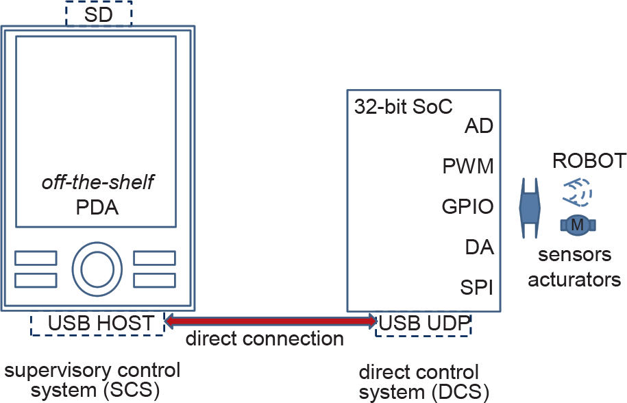
The overall architecture is presented in Figure 1 and an integration model is presented in Figure 2.
Proposed software architecture of hybrid control system of the robot
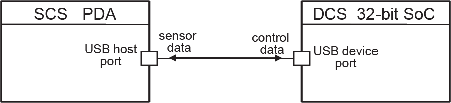
Model of integration
From the software perspective, it is proposed to utilize standard libraries and their optimization. The use of a 32bit SoC class micro-system with the built in USB-UDP full-speed port for the DCS unit is proposed.
The system proposed in Figure 1 and Figure 2 was realized in practice.
3.1 Hardware architecture
The system was constructed using the SoC micro-system – AT91SAM7X and PDA – Fujitsu-Siemens N560 with Windows Mobile operating system. The AT91SAM7X micro-system serves as the measurement-executive unit (DCS) of the system, by means of which measurements and PID control with a relatively high frequency are conducted. The supervisory control, logging and visualization unit (SCS) is executed by the PDA.
The micro-system AT91SAM7X-256 includes, among other elements, the fully programmable full-speed USB user device port (USB-UDP 2.0), 32-bit core ARM7TDMI, 256kB FLASH memory for storing programme code, 64kB RAM for data storing and processing, eight-channel AD transducer, four-channel SPI port, TWI/I2C port, four-channel PWM generator, UART ports, CAN port, EMAC port, ten-odd timers and dozens of input-output lines. The functionality of particular lines is programmable [14, 15]. Each block can be individually switched off in order to reduce power consumption. It is worth mentioning that most of the peripheral devices have their individual DMA channels. This enables relief the CPU core from the tasks of transmitting data between the device and memory. The SPI port can be easily utilized for connecting AD and DA transducers if there is a requirement of better metrological characteristics than of the built-in transducer. It can also be easily used for extending memory resources.
The core used in the experiments has an efficiency of 48 MIPS (millions of instructions per second), and 32-bit architecture enables processing of measurement data with a sufficient precision. In contrast to 8-bit controllers, there is no requirement for a software emulation of 32-bit calculations. Calculation performance is sufficient for the realization of controlling algorithms, e.g., the PID for several control paths.
Existing memory resources allow C programming. A free GNU C compiler was used in the presented realization.
The PDA runs on PXA270 CPU, 620MHz and has, among other elements, the USB host controller [16], colour touch panel, and 64MB of RAM and FLASH memories. The slot for SD cards enables the recording of large amounts of data, as well as long-term recording.
3.2 Operating system
Following [17], Windows CE/Mobile as a software platform was addressed for the programming of the real-time and embedded applications. The idea was to provide both similar functions as in desktop versions of the system and the real-time kernel. For example, interrupt servicing is divided into two stages: interrupt service routine (ISR) and interrupt service thread (IST). This mechanism is similar to the one used in QNX where a proxy can be triggered within ISR, to awaken a task. Interrupt service latency is guaranteed. The formula for calculation of the worst-case latencies can be found in [17]. Some other information about real-time kernel and examples of latencies and thread switching time can be found in [18].
Windows CE/Mobile consists of, among other things, kernel managing processes and modules operating external devices [19]. Some methods of process scheduling are presented in [20].
Windows CE is used in industry in embedded PLC controllers [21]. Interrupt service routine latency is 14 µs and as such is reported in the literature. The study of Windows CE usages for real-time interpolation calculations in numerical control (NC) with 1 ms cycles is presented in [22].
CNC control system realization with the use of specialized hardware connected to the main CPU bus is presented in [23]. However, this requires the writing of a specialized device driver. This system is targeted to work in 1 ms control cycles.
3.3 Software architecture of the USB communication
USB full-speed standard ver.2.0 defines four types of transactions: isochronous, control, interrupt, bulk [3]. Isochronous transactions have a guaranteed execution time that equals one millisecond and is performed in every bus cycle. Although isochronous transactions can be used for performing hard real-time tasks, their disadvantage is their limitation of bandwidth to only 64 kB/s. Control and interrupt transactions can be performed once at most in a one millisecond bus cycle. This property also limits the available bandwidth. Only bulk transactions can be repeated many times during every bus cycle.
The SAM7X micro-system, equipped with the USB-UDP port, was fully software configured. This can represent a device of pre-defined standard classes [24]. It is also possible to implement a custom protocol, specified in the standard as ‘vendor specific’. The implementation of the CDC-ACM class (communications device class abstract control model) [25] was assumed. The advantage of the CDC class is the implementation of bulk transactions. The number of transactions in a single 1 ms USB frame can be higher than one. This offers a better band utilization in comparison to the HID class [26]. The HID class has a limitation to one control or interrupt transaction result of stream bandwidth reduction. The second selection criterion was the provision of a compatibility with a popular standard. This enables the use of typical software drivers for this class. They are available for numerous operating systems, including Windows CE/Mobile.
The PDA was programmed using the Visual Studio environment. This requires package installation for programming devices with Windows CE and Mobile operating systems. It includes libraries of elements for the graphic user interface (GUI) and communication libraries. They are available for several programme languages, such as C/C++, Visual Basic, and .NET. The last two enabled a rapid graphic user interface implementation by means of a graphic application constructor. General programming knowledge proved sufficient for the proposed conceptual approach.
4. The experimental real-time results of subsystems and methods of optimizations
In practical implementations of mobile robot control systems, the supervisory control system in the PDA is required to receive relatively large amounts of sensor data. The size of the received packages ranges from 64B to 4kB and contains measurement data and response codes, sampled at high frequency. The stream of sent data is substantially smaller and usually limited to sending short commands controlling the settings of DCS units. Thus, sending packages of the size of dozens of bytes is a typical condition of the USB connection work. It is sufficient for coding commands, their parameters and the state of the DCS part.
4.1 Experimental results of real-time performance using standard components
The standard software CDC protocol driver was used for the aims of realization of data exchange between the direct control subsystem and the supervisory control subsystem of the robot. It is a layer mediating between the USB host driver, provided with the operating system, and the user application. Its task is to hide from the application details concerning a physical USB connection, such as size and number of the USB plug or the method of transaction scheduling, etc.
Experimental results of implementation, obtained using standard programming methods, are presented in Figure 3. It is assumed that output packages contain commands for the measuring-executive unit and that their size is 64 B. The results were compiled for the selected sizes of the received packages: {64, 128, 256, 512, 1024, 2048, 4096 B}.
The analysed values include the maximal and mean time of packet exchange between acquisition and execution. Its equivalent to the closed control loop time, along the DCS-SCS-DCS path (Figure 2) expressed in [ms/cycle] and the sensor data stream possible to achieve, expressed in [kB/s], were investigated. The application realized only the communication task, without saving to the SD (Secure Digital) card and visualization. The system was loaded by standard processes. The presented results are averaged from 10,000 experiments performed by the author of this paper. It is worth mentioning that maximal times were rarely observed during experiments.
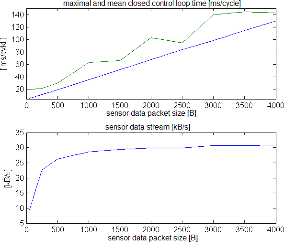
Experimental real-time results depending on the size of received packages. a) Maximal and mean time of closed control loop time expressed in [ms/cycle] b) Average stream of received sensor data expressed in [kB/s].
Discussion of the results
The exchange of packets using a standard CDC class data driver with its standard parameters resulted in rather long times; e.g., for a packet size of 1 kB, the maximal time reaches 62 ms (Figure 3). This limits the execution of the control task to only 17 times per second. The maximal time of package exchange is crucial from the perspective of the real-time control system and stream continuity. It defines the upper bound of the time limit, which can be regarded as an experimentally obtained deadline. The knowledge of the deadline mentioned above is necessary for determining the sizes of buffers at the DCS side.
The mean time is essential for soft real-time systems. It increases linearly with the size of the received packages as can be observed in Figure 3. This parameter can be regarded as a soft deadline; e.g., for a packet size of 1 kB, mean time equals 37 ms. This means that the soft real-time control can be performed almost two times faster than in hard real-time.
Better real-time results can be achieved by decreasing the package size; however, the mean bandwidth is significantly reduced in such a case (Figure 3.b).
The obtained results can be regarded as typical since the standard CDC drivers are designed for work with devices emulating RS232 class series connections, character terminals, modems, etc. The required working speeds are not high in the case of these devices. The achieved stream of the order of 30 kB/s is comparable with a classic serial connection of 300 kBps speed and allows the construction of measuring and logging systems of a speed of the order of 10–15 kSPS. The obtained results are comparable with those given in [27].
Modifications to the application's working environment (e.g., increasing its thread priority) neither cause changes in the mean time of package exchange nor in the mean speed. However, they reduce the maximal exchange time, which is a significant result in real-time systems.
4.2 Optimization of the CDC driver
Optimization was proposed after in-depth analysis of CDC driver work. Standard CDC class drivers were designed to exchange small amounts of data, usually single bytes, between them and the system USB host controller. It is possible to optimize this behaviour by modifying the driver source codes, to speak more precisely by rearranging buffer handling as well as increasing their sizes. However, it is necessary to keep to the rules of the operating system, as it is required to have memory allocations with physical rather than virtual addressing (indispensable for the DMA controller of the USB host).

Experimental real-time results and the average stream after driver optimization
It was possible to increase the buffer to 4 kB in the analysed solution, as this was the allocation unit that the system handled. It is also equal to memory page size. The proposed optimization involves changes in the driver source code and its re-compilation.
Results of experiments for the system with the optimized CDC driver are shown in Figure 4.
Discussion of the results
The differences between the results of this experiment, compared to the results of the former experiments were by order of magnitude better.
It must be noted that maximal exchange times were significantly reduced to the value of the order of 20 ms. Maximal times were rarely observed; however, they must be considered during the design process of the overall system.
Times of small package exchange, in terms of mean and maximal values, amounted to 5 ms and 7–15 ms, respectively. Their values are mainly influenced by the work of the USB host controller subsystem with the host itself integrated in the CPU. The total exchange time includes scheduling of transaction sending, sending of transaction, scheduling of receiving transaction, and receiving transaction. The result is restricted by the duration of the basic cycle of the USB bus (1 ms) that the host controller (built into the PDA) synchronizes with. Further decreasing of times is possible only after a complete rewriting of the host driver. However, this required an intervention into the operating system and was not implemented.
It is possible to achieve a bandwidth of up to 600 kB/s in the case of large packages of 4 kB. In the same conditions, a significant reduction of the mean time of package exchange was achieved. This is especially noteworthy as far as large streams were concerned, e.g., maximal time was 17 ms and mean time was only 7 ms. These results should be compared to 142 ms and 130 ms obtained before optimization.
The load of the SAM7X micro-system was of the order of 40% in case of maximal streams [28].
4.3 Time performance of logging module and its optimization
In mobile and embedded devices, SD memory cards or internal FLASH memory are used as mass storage functions. Such media are resistant to mechanical shocks and store data after switching off the power. In the case of control systems possessing recording functionality, it is essential to analyse time characteristics of the recording subsystem and, if necessary, to optimize both the response time and the data stream speed. They have a substantial influence on the overall parameters of the solution.
4.3.1 The realization of recording with the use of standard software modules
Experimental results of time characteristics of recording to the internal FLASH memory are presented in Figure 5. A record of a data block of a particular size during one call is marked by the term ‘single transaction’. The assumed block sizes are: 60, 250, 512, 1k, 2k, 4k, 8k, 16k, and 32k. These blocks were written to the internal memory during the experiments. Standard libraries, available in the programming environment, were used. The system was loaded with standard working processes. The presented results were averaged from 10,000 transactions.
The achieved stream speeds are not high (of the order of 200kB/s). Higher stream speeds for small transactions are related to the system buffering which ceases to be efficient for larger streams.

Results of recording data stream to internal FLASH memory storage according to the size of a single transaction
The experimental results of recording to the SD card are presented in Figure 6.

Results of recording data stream to SD memory card according to the size of a single transaction
Discussion of the results
A relatively high mean and maximal transaction times are achieved for smaller data blocks. These results are caused by the file system driver, which is aimed at the minimization of the risk of data loss during rapid removal of the SD card without its unlocking. In such case, the operational system conducts an immediate physical saving. It results in an each-time modification of the 512 bytes sector of the SD card, even if the number of saved bytes is lower.
A substantially higher average stream was achieved for transactions over 1 kB than in the case of internal FLASH memory chips. For example, for a transaction of 4 kB in size, it is possible to save a stream of 550 kB/s. However, an increase in the transaction size enlarges the maximal as well as mean times of its execution. From the perspective of the real-time system, the maximal execution time is determined mainly by the time of recording in the physical FLASH memory sector.
It is suggested to use small package sizes of data incoming from the USB communication side and software buffered at the application stage. They should then be saved into the SD memory in the form of larger blocks, e.g., 4 kB in practical implementations of control and logging systems.
While the streams achieved with this simple serial architecture of subtasks are large, the response times of the communication and logging subtasks are summing up, which causes a drop in the overall performance.
Logging tasks do not possess any deadline; the main goal is to guarantee the data stream continuity. Since Windows CE/Mobile is a multitasking system, the logging task can be executed in the other thread.
In general, the optimization of the transaction time and maximization of stream speed is to be taken into consideration. Minimizing transaction times results in a reduction of CPU load as well as hardware resources. Freed resources can be allocated to other concurrent threads.
Optimization of maximal time is also important, so its result influences memory size requirements.
4.3.2 The proposed method of optimization – modification of cluster size
After a thorough theoretical study of file system structure, which is referred to in [29], record optimization is proposed by the author. Some aspects of this are discussed below. Data stored on the SD card (as well as on other mass storage media such as pen drives, HDDs) are organized in a particular format, described by detailed file system parameters. During the realization of saving data on a medium, there is an allocation of the so-called cluster of a particular capacity. Its size is a multiplicity of the basic sector of 512 B size. Information about free and occupied clusters, together with their location in the physical sector space, is stored in a special section of the file system, called allocation tables. They constitute the most critical fragment of the file system, and in order to increase storage safety two copies of the allocation tables are usually used.
During recording, the file system driver must search allocation tables in order to find a free cluster in which the data can be stored. This happens when data added to a file exceeds cluster limits. After finding such a cluster, there must be recording of sectors in allocation tables in order to update information about the cluster occupation. Updating is performed in two physically independent allocation tables. The execution of the actions mentioned above results in time losses related to saving sectors of the FLASH memory on the SD card.
The number of sectors per cluster depends mainly on partition size, but it is possible to modify it within a particular limited range. Detailed information can be found in [26].
The recording optimization proposed in this paper involves an increased number of sectors per cluster. It causes a decrease in the number of necessary modifications of allocation tables and enables an increase in the average stream.

Recording optimization − 2 kB per cluster

Recording optimization − 16 kB per cluster
The experimental effects of optimization are presented in Figures 7 and 8 for two possible formats for the particular SD card: 2 kB/cluster and 16 kB/cluster. The achieved results should be compared with the results for the default format of 1 kB/cluster presented in Figure 6.
Discussion of the results
It was observed that the maximal transaction time decreased about two times (Figure 8) in comparison to the 1kB/cluster format (Figure 6). The attention should be directed to a significant reduction of the mean transaction time. It is a very essential parameter in the context of the overall performance of the control system equipped with the logging module, and it has a great influence on the overall efficiency. Thus if the logging module consumes fewer resources, these resources can be used in the other threads. There is also a significant growth in the registration speed, up to 1500 kB/s (Figure 7) and 2500 kB/s (Figure 8) in comparison to the 1 kB/cluster format (Figure 6).
4.3.3 The proposed method of optimization – pre-allocation of the chain of clusters
Having investigated theoretical resources on file system structure [26], the author presents further possibilities of optimization. These enable decreasing maximal response times and increasing mean stream speed. This involves pre-allocation of the chain of clusters in allocation tables. After this operation, there is no need for further modifications of the allocation tables or scanning for free clusters during the data stream recording. There is also no need to update the file size in the input directory sector (so-called file entry).
Figures 9 and 10 illustrate the experimental results for the maximal and mean response times and stream bandwidth after optimization.

Recording optimization – pre-allocation of clusters chain, 0.5kB per cluster

Recording optimization – pre-allocation of clusters chain, 4 kB per cluster
Discussion of the results
A very distinct improvement of the recording subsystem performance was observed. The reduction of the maximal response time was achieved, which is very significant in the real-time system. It can be exemplified by the following: for a 4 kB transaction the maximal time achieved was only 5 ms and the mean time was 2 ms (Figure 9). This was accompanied by an increase of the average stream recording speed to 2500 kB/s. A further increase in the transaction size enables boosting of the stream to 3000 kB/s. However, the maximal and mean times are increasing in such cases. Better parameters can be achieved for a larger number of sectors per cluster (Figure 10) and transaction sizes of 8–16kB. The stream of the order of 3000 kB/s was achieved at the maximal transaction time of 6 ms and the mean one of 3 ms.
A certain disadvantage of the solution presented is that it is necessary to determine the predicted size of the acquired data for the cluster pre-allocation. However, this size can be easily calculated on the basis of the stream speed multiplied by the required measurement time. An alternative method would involve pre-allocation of a sufficiently large number of clusters, e.g., covering a 2 GB result file.
5. Experimental real-time results of the entire acquisition-control-recording system
A simple, single thread system realization in the form of a loop alternately executing data communication from the USB connection and, next, saving them onto the SD card is not efficient. In such a solution, the addition of maximal as well as mean response times takes place. It results in a degradation of parameters, which is unfavourable for real-time systems.
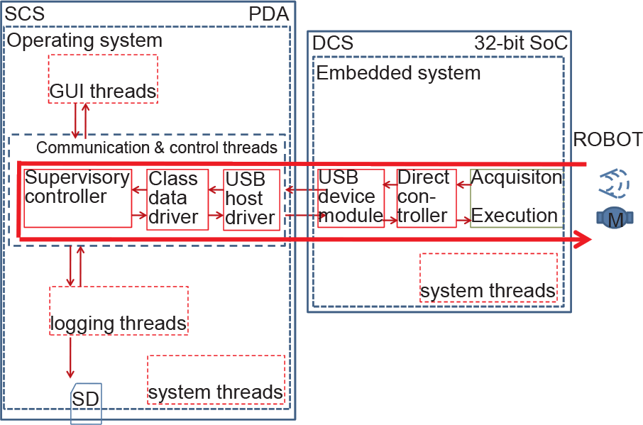
The proposed software architecture of hybrid control system of the robot
From the software point of view, the proposed architecture consists of several functional blocks with many threads, as shown in Figure 11. The main communication thread performs the data exchange in cooperation with the USB drivers stack. In the same thread, the supervisory controller computes output values for actuators. The other threads handle continuous data logging and graphical user interface.
The cooperation of communicative, recording and GUI software modules was proposed and realized in the architecture of the three-thread application. Communication and recording threads were written in C/C++. The user interface was created using the graphic constructor,.NET libraries and C# language. Due to the asynchronous functioning of these threads and various package sizes, there was the necessity for realizing the multiple buffering. Sixteen-times buffering (between the thread receiving data from the USB connection and the thread saving data onto the SD card) was accepted on the basis of the results from section 4.3., specifying maximal response times.
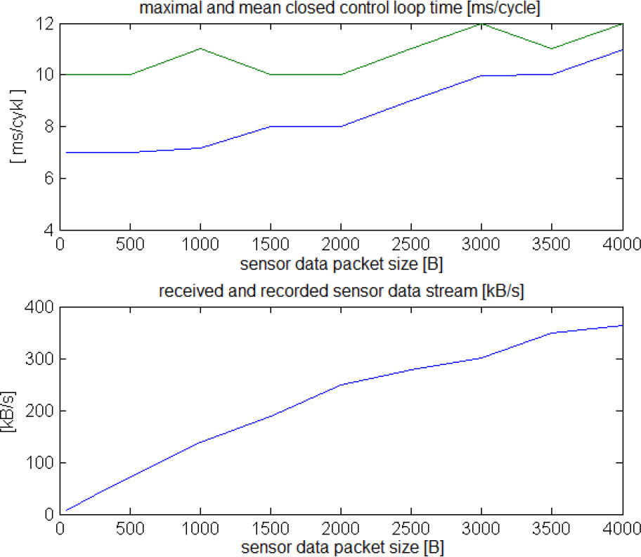
The experimental results are presented in Figure 12, showing real-time performances of the entire control and measuring-recording system in dependency on various sizes of packages {64, 128, 256, 0. 5k, 1k, 1. 5k,… 4k} received through the USB connection. During the control and acquisition-recording, the application screen was not refreshed and all threads were at default priorities. A pre-allocation of clusters was also conducted. The presented maximal and mean transaction times concern the USB communication part, which is crucial for the control task. It is a measure of the system quality in controlling and acquisition-recording implementations in which the PDA can conduct additional calculations and can be included in the control loop in real time.
Discussion of the results
As is seen above, the mean time determining a possible control-loop cycle in soft real-time systems does not exceed 7 ms. The maximal time was observed sporadically; however, it determines the worst case of work. The maximal time is a boundary for hard real-time systems. Its substantial increase was caused by pre-emption by another process, which is shown for the 1.5 kB transaction size. It is possible to receive and record a continuous data stream at a speed of 580 kB/s in case of packages of a size of 4 kB. It enables the construction of the control and recording systems of the bandwidth of 290 kSPS 16bit.
The screen refreshing activation results in a system quality degradation, due to the necessity of executing a time-consuming graphical operation by the PDA CPU. A speed drop depends on the amount of refreshed elements, e.g., font size and refreshing frequency. The examples of results are presented in Figure 13. Ten measured values, with 20-point font, were refreshed during the experiment. The refreshing thread frequency was 10 Hz. The refreshing of the GUI took from 40 to 50 ms, depending on the data value on the screen.

Experimental real-time results of the entire control and acquisition-recording system without screen refreshing

Experimental real-time results of the entire control and acquisition-recording system with screen data refreshing
Under such work conditions, the maximal time is determined by the GUI refreshing thread. However, it should be noted that it is smaller than the sum of the worst cases observed for single threads. Despite the fact that, theoretically, such a worst-case scenario can occur, it was not observed.
The average stream was reduced to 300 kB/s for 4 kB packages, as the CPU had to handle three tasks (communication, SD memory, GUI) at the same time. The mean transaction time also increased up to 14 ms.
5.1 Overall system optimization
On the basis of thorough theoretical study of thread scheduling [17], the optimization of the entire system is proposed. Since it is crucial for reducing the influence of the GUI thread, this problem can solved by increasing the priority of the USB communication thread and SD writing thread. Thanks to this, screen operations can be pre-empted by communication tasks. However, this change of task priorities requires additional double buffering and proper synchronization of data flow.

Experimental real-time results of the entire control and acquisition-recording system after optimization, without screen refreshing
Experimental results after the system optimization are presented in Figures 14 and 15, without and with the screen refreshing respectively.
Discussion of the results
In comparison to the pre-optimized solution (compare Figure 12 and 14), the results are characterized by a significant decrease in the maximal response time. It is possible to maintain the control loop cycle time within 15 ms and the mean time within 9 ms, whereas there was a growth of stream speed to 440 kB/s.
After optimization, there was a substantial reduction of an unfavourable influence of the screen refreshing thread (compare Figures 13 and 15). The observed maximal times did not exceed 14 ms while the mean time amounted to 9 ms and stream was 440 kB/s. The obtained optimization results are very similar to those for the case with inactive refreshing (compare Figures 14 and 15). This means that optimization significantly reduced the screen thread influences on real-time control performances. Such good results were achieved thanks to the proper pre-emption of screen threads at key moments of the USB communication and recording thread activity. One disadvantage of the presented realization is the fact that other processes are unable to use the SD card resource and require waiting for the saving thread end.

Experimental results of the entire control and acquisition-recording system after optimization with screen data refreshing
Experimental results of the entire control and acquisition-recording system under the load of 3200 floating-point operations per transaction
It is also essential to study the time characteristics of the system considering the numerical task loading during control implementations. Figure 15 presents the results of the realization of floating-point numerical calculations.
They can represent the PID or predictive regulator calculations, multiplication of matrixes, conducting additional filtrations, correlation calculations, etc. A total of 1600 floating-point multiplication and addition operations of a single precision were executed during processing. Calculations were synchronized by a data exchange in the USB communication part every 7–12 ms.
The obtained results show that an additional floating-point calculation load has an influence on the results achieved. As far as the mean and maximal times are concerned, it is an additive relationship. The mean time increases proportionally to the amount of calculations and its gain depends on the speed and performance of the PDA's CPU. The operating system has only a trifling influence on the obtained results.
6. Conclusions
The proposed USB communication optimizations allow a substantial increase in the real-time performance of the control task.
In the regime of hard real-time, the control task was executed of the order of 15 ms compared to 100 ms before optimization. Furthermore, the operational data stream and events can be recorded up to 380 kB/s. The control task was executed in 8 ms for the smallest packets of sensor data.
In the regime of soft real-time, closed control loop time of the order of 5 ms was obtained. This means, that for applications for which exceeding the operational deadlines is not critical, an additional software component, such as a trajectory planning or set points computing for PID controllers modules, can be incorporated.
The bandwidth of the order of 400–580 kB/s was achieved in simultaneous control and registration of sensor data. Thus, it enables the construction of mobile robot control and acquisition-recording devices, e.g., of 16 analogue sensors at the frequency of 12 kHz.
Moreover, the proposed system can be considered as a general framework. Hence, it can be useful for rapid prototyping of the control system. The advantage is its miniature size and low power suitable for mobile robots. The use of the off-the-shelf PDA component reduces both the effort of its implementation and the cost. The framework allows the implementation of the advanced superior regulators, such as predictive or LQ regulators.
The presented methods of the optimization of the embedded dual processor system can be utilized for off-the-shelf hardware solutions running on Windows CE/Mobile operating systems.
Footnotes
7. Acknowledgements
The paper was prepared within the grant PBS/1/A9/1/2012 founded by National Centre for Research and Development (NCBiR).