
Abstract
In real-time hybrid testing, systems are separated into a numerically simulated substructure and a physically tested substructure, coupled in real time using actuators and force sensors. Actuators tend to introduce spurious dynamics to the system which can result in inaccuracy or even instability. Conventional means of mitigating these dynamics can be ineffective in the presence of nonlinearity in the physical substructure or transfer system. This article presents the first experimental tests of a novel passivity-based controller for hybrid testing. Passivity control was found to stabilize a real-time hybrid test which would otherwise exhibit instability due to the combination of actuator lag and a stiff physical substructure. Limit cycle behaviour caused by nonlinear friction in the actuator was also reduced by 95% with passivity control, compared to only 64% for contemporary methods. The combination of passivity control with conventional methods is shown to reduce actuator lag from 35.3° to 13.7°. A big advantage of passivity control is its simplicity compared with model-based compensators, making it an attractive choice in a wide range of contexts.
Introduction
Real-time hybrid testing (RtHT) is a method of analysing complex systems utilizing a combination of experimental and simulation-based techniques. The complete system is separated into numerical and physical components which are tested together, with actuators and sensors to couple the substructures in real time. A number of advantages of this technique are detailed by Plummer 1 : the method not only enables cost savings in not having to set up the complete experimental system but also enables testing of systems which are too complex for simulation or too large for conventional experimental testing. Moreover, RtHT offers further advantages such as enabling systems to be tested prior to the design or realization of all physical components, while enabling system parameters to be easily adjusted by the user. 1
A drawback of RtHT is the dynamics introduced to the system by the actuators. The delay and lag added to the closed loop system often leads to tracking errors and sometimes renders the system unstable. Several authors propose delay compensation methods to minimize this effect. Horiuchi et al. 2 propose a delay compensation scheme which steps forward by a fixed time delay based on a linear extrapolation of the past response of the system. A table of coefficients is available which enables the user to easily implement an nth order forward predictive scheme to mitigate the delay of the actuator. However, this forward stepping algorithm only compensates delays of integer multiples of the simulation time step. Wallace et al. 3 present an improved scheme which compensates continuous delay times by adaptively tuning the time constant. However, these schemes depend on the actuator behaviour being akin to that of a pure delay although the dynamics of real actuators are often more complex. Wallace et al. 4 utilize a compensation scheme where the actuator is modelled as a linear first-order transfer function. The transfer function model is inverted and applied as a discrete time feed-forward compensator to mitigate actuator dynamics. du Bois et al. 5 take this technique a step further by modelling actuator dynamics using combinations of first- and second-order transfer functions with delays.
Tang et al. 6 review some of the state-of-the-art delay compensation schemes used in RtHT. For most schemes, the author concludes that improvements in performance were mostly seen within a narrow frequency range. Outside this range, the schemes resulted in degradations of amplitude ratio and phase. This is as expected, since delay compensation schemes estimate the actuator response ahead of the anticipated time delay using various linear polynomial approximations. For highly nonlinear systems where the fidelity of linear methods is lower, satisfactory compensation is difficult to achieve.
A novel adaptive filtering scheme, which aims to function for both linear and nonlinear systems, is proposed in the work of Bartl et al. 7 The authors utilize an optimization algorithm to augment the actuator input, thereby synchronizing the numerical and physical substructure displacements. This mitigates actuator delay allowing good tracking performance. The method is based on a least mean squares optimization algorithm which converges the substructure position error to zero, over time. Unlike most preceding state-of-the-art schemes, this compensator requires no model of actuator dynamics to function correctly which makes it widely applicable to a range of hybrid tests. However, one limitation of the scheme over conventional feed-forward schemes is the finite time taken to achieve convergence. This makes the scheme unsuitable for highly discontinuous tests such as crash tests where changes in the system must be rapidly compensated for. An improved adaptive feed-forward filtering scheme is presented in Bartl et al., 8 where a more sophisticated recursive least square adaption law replaces the least mean squares law, enabling faster convergence. Nevertheless, both schemes suffer from the limitation that they require the hybrid test to be initially stable as they are unable to restore the stability of hybrid tests made unstable by actuator lag.
Ou et al. 9 propose a feed-forward actuator control scheme based on H∞ optimization and linear quadratic estimation. A three-storey building with damping is emulated in a 3-degree of freedom hybrid system. The damper is set up as the physical substructure and is coupled to the numerical substructure of the building using a hydraulic actuator. The proposed algorithm is seen to be effective in cancelling noise which is amplified by the size of the controller gain of the actuator in the hybrid test. Real-time hybrid simulation results indicate good tracking of position and velocity, although excitation signals used are of low frequency where actuator lag is notably smaller than at higher frequencies.
Lag-compensation technology to date is based on the identification of a linear model of the actuator which is used to design a feed-forward controller to mitigate the actuator’s lag. Often, it is difficult to accurately model the actuator dynamics using a delay and/or linear transfer function especially when the dynamics of the actuator are affected by the physical substructure of the test. Moreover, nonlinearities, such as Coulomb friction, result in unpredictable behaviour, often depending on the operating conditions. While high-fidelity models of the physical system and test specimen can, in principle, be used along with nonlinear control methods to mitigate these effects, the effort of implementation is high, and the understanding of the physical specimen required undermines the purpose of the hybrid test. It is for this reason that such techniques are rarely employed, and the state of the art usually relies on simple linear theory. Therefore, there exists the need for a more robust scheme with less dependency on the transfer system behaviour.
In this article, a passivity-based approach is proposed where the energy flow between the numerical and physical substructures and the transfer system is measured and used to set the damping coefficient of a virtual damper. This triggers the dissipation of spurious energy introduced by the actuation hardware. Excess transfer system energy can result in poor simulation accuracy and more critically, instability in the hybrid test. Even where high performance actuators and control techniques are incorporated to mitigate the addition of such spurious energy, passivity-based methods can supplement that control to extend the useful operational envelope of the equipment and improve upon the state-of-the-art. The work presented here is the first experimental investigation of the methods initially explored in Peiris et al. 10
Passivity control regulates the energy in a hybrid test using a damping element to maintain stability regardless of the class of system being tested. As such, the scheme has the potential to guarantee stability of hybrid tests unlike any of its preceding state-of-the-art compensation schemes. With the assurance of stability, hybrid testing can be applied to a wider range of nonlinear systems which would otherwise not be compatible with hybrid testing due to the lack of accurate models to predict actuator behaviour. Applications of RtHT include seismic integrity testing of building structures in the civil engineering industry, 11 powertrain and suspension design in the automotive sector, 12 air-to-air refuelling in the aerospace industry 13 and testing of wave energy harvesting devices in the marine energy sector. 14 The aerospace industry and automotive sectors have turnovers of £72 billion and £71.6 billion in the UK alone as of 2017.15,16 As an illustration of the time and cost savings that can be realized using hybrid test systems, National Instruments report field testing time reductions from 20 to 5 days for an aircraft arrestor system, at a cost saving of around $49,000 per day. 17 The benefits of analogous hardware-in-the-loop systems for electronic controllers have long since been established, with lead time reductions estimated at 15%−50%. 18
Section ‘Theory and method’ describes the structure and theory of the passivity controller proposed in this article together with a description of some state-of-the-art transfer dynamics compensators which are used to compare results. Section ‘Experimental system’ presents the hybrid system used for testing the passivity controller together with a description of the actuator used in the transfer system. In section ‘Simulation results and discussion,’ simulation results are discussed, and experimental results are presented and discussed in section ‘Experimental results and discussion’.
Theory and method
Passivity control
A system which is dissipative with respect to the energy supplied to it is known as a passive system. 19 Passivity control is widely applied in haptic interface systems in the teleoperation industry to maintain stable communication between master and slave manipulators. Zefran et al. 20 argue that passivity control can be used to guarantee stability in teleoperation systems as long as appropriate operating conditions are maintained throughout the tests. RtHTs are analogous to haptic interface systems in the sense that the delay in the transfer system between the numerical and physical substructures is similar in nature to that between the master and slave manipulators.
Atashzar et al. 21 illustrate the effectiveness of passivity control in a human–robot interaction system where assistive and resistive therapy is delivered to a patient’s limb. Results indicate that passivity control alleviates delay induced instability. The authors further acknowledge the fidelity of the proposed solution in the face of nonlinearities in the system such as variable time delays. As conventional model-based compensation schemes in hybrid testing are often based on linear models, performance is compromised in the presence of nonlinearity in the system and passivity control offers a means to address this deficiency.
Sun et al. 22 apply a modified passivity control approach based on a wave variable to accommodate time delays in a teleoperation system. Results are seen to indicate good tracking between master and slave manipulators with a maximum error of less than 1 radian in response to low frequency inputs. Zhang and Cheah 23 utilize passivity control to stabilize a rehabilitation robot system used for motion recovery training in stroke patients. In this work, passivity control has been utilized to enable a smooth transition of the system between different operating modes. This can be exploited in RtHT, particularly in nonlinear systems required to operate under several test conditions in a single experiment.
A recent application of passivity control is seen in the work of Xie et al. 24 where passivity theory is used to maintain the stability of a cascade nonlinear system comprising of two switched systems. An output feedback control law together with a state-dependant switching signal is used to achieve passivity and therefore stability of the closed loop system. In a 2-degree of freedom simulation of a robot arm manipulator, the author demonstrates the efficacy of the scheme in decaying the state trajectories of the closed loop system to zero asymptotically over time. This research illustrates the strong stabilizing properties of passivity regulation to maintain stability in complex systems which cannot be accurately described using linear models. The uniqueness of passivity theory lies mainly in its versatility as it can be used with various control laws as required by specific applications in order to maintain stability of the dynamic system.
Furthermore, another recent publication by Gil-González et al. 25 evaluate the usefulness of passivity control in the energy distribution sector. A passivity-based direct power control scheme for electrical energy storage systems in alternating current (AC) microgrids is proposed. The novel scheme does neither rely on a conventional inner-loop current regulator nor rely on a phase-locked loop, thereby increasing the reliability of the system while reducing overall costs as well. As with the application of Xie et al., 24 asymptotic stability is achieved in the closed loop system. Simulations were used to compare the performance of the novel passivity-based system with that of a conventional vector oriented direct power model with feedback linearization. It was shown that the passivity-based scheme outperformed the conventional system in controlling both the active and reactive powers and in mitigating power oscillations in the grid. The versatility of passivity control is illustrated once again through this publication which demonstrates the potency of passivity concepts in the field of electrical engineering.
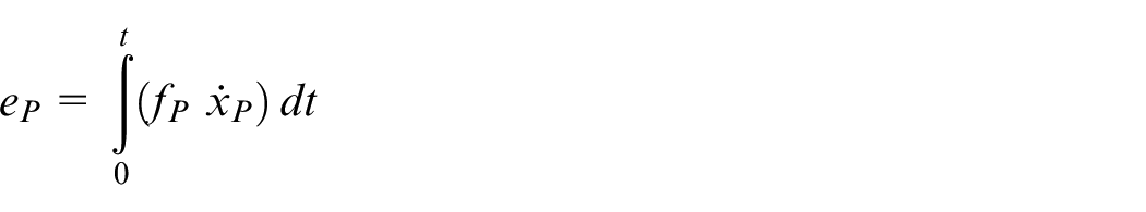
The passivity controller for hybrid testing proposed in this article acts upon the energy flowing to the numerical and physical substructures. The energy error, that is, additional energy introduced by the transfer system

where
Similarly, the energy
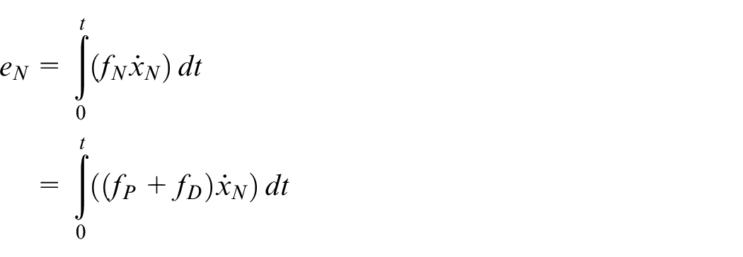
where

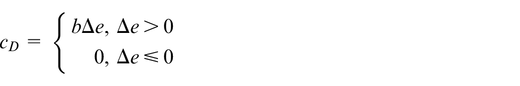
This energy difference is used to calculate the damping rate at the virtual variable rate passivity damper. However, if the energy flowing from the numerical substructure to the actuator exceeds that flowing from the actuator to the physical substructure, it is desirable to turn off passivity control action. This is done to prevent the addition of negative damping to the system as this can make the closed loop hybrid test unstable. The passivity damper rate
Friction compensation theory
The actuator used in these studies exhibits nontrivial Coulomb friction; this is compensated as proposed by Eamcharoenying et al.
26
in order to minimize spurious effects. This scheme for deterministic systems is based on applying a step in the command current to the actuator in order to mitigate the expected Coulomb friction force. The friction force in the model,
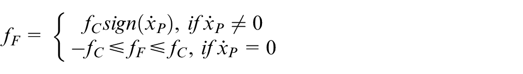
where
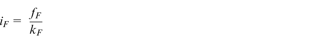
The command current signal to the actuator is therefore augmented as follows in order to cancel the Coulomb friction force

where
Model-based compensation theory
In order to compare the performance of passivity control with a state-of-the-art compensation scheme, a second-order lag compensator as utilized in du Bois et al. 5 is designed to mitigate the transfer dynamics of the actuator in the presence of the physical substructure. A transfer function of the coupled dynamics of the actuator and physical substructure is required for the design of the lag compensator. To obtain this, the actuator with the physical substructure and friction compensation was swept sinusoidally from 0.1 to 50 Hz over 50 s at low amplitude (2 mm) and the output position data were measured and used with the input demand for transfer function identification. The second-order transfer function is fit to the data using the Gauss–Newton least squares search method
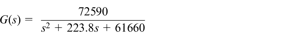
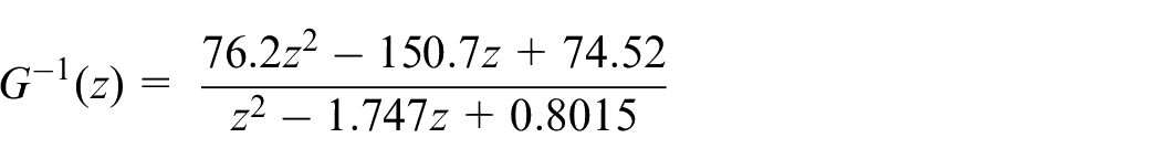
where G(s) is the transfer function modelling the dynamics of the actuation hardware and is therefore expected to always have stable poles. The identified transfer function G(s) is then inverted by placing the identified poles as zeros. A pair of conjugate poles 10 times faster than the identified conjugate poles are placed in the denominator of the inversion thereby maintaining causality. The inverted transfer function is then discretized at 10 kHz using Tustin’s approximation and subsequently implemented as a feed-forward compensator to mitigate the actuator dynamics. The model-based compensator is given by the following discrete time transfer function
Experimental system
Transfer system
The transfer system of the hybrid test consists of an actuator to apply the displacements calculated in the numerical substructure to the physical substructure, a load cell to feedback physical substructure force measurements to the numerical substructure, and the passivity controller. The actuator used for hybrid testing in the following experiments is a Copley STA2508S electromagnetic actuator.
The actuator is programmed to operate in force control mode using the proprietary Xenus XTL motor driver. The motor driver executes a current control loop serving as the inner-loop controller which drives the actuator. Nested outer control loops acting on position and velocity feedback are programmed in a Simulink real-time target controller to allow the actuator to track position in the hybrid tests. The structure of the actuator control system is shown in Figure 1. The actuator has a built-in quadrature encoder for position measurement and feedback. The position measurements are differentiated to obtain velocity feedback. The performance limits of the actuator are summarized in Table 1. Nonlinear sliding friction acts on the armature of the actuator. To minimize the effect of nonlinear friction in the hybrid test, a Coulomb friction compensator as proposed by Eamcharoenying et al. 26 is applied in the Simulink real-time target controller which also executes the position and velocity control loops of the actuator.
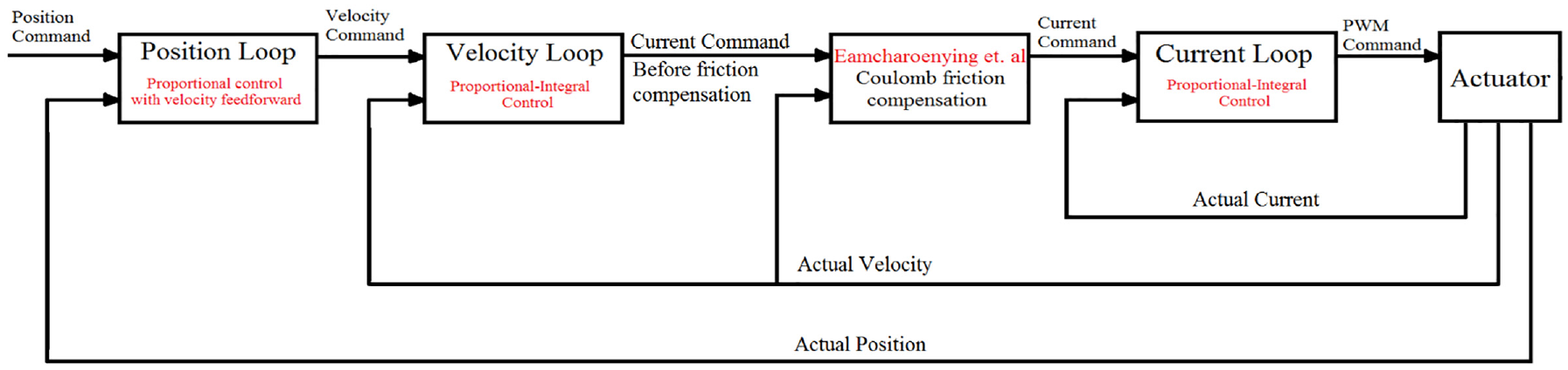
Actuator control system structure. 27
Actuator performance limits.
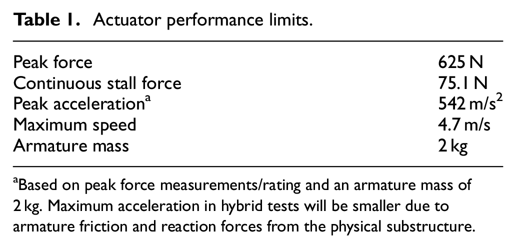
Based on peak force measurements/rating and an armature mass of 2 kg. Maximum acceleration in hybrid tests will be smaller due to armature friction and reaction forces from the physical substructure.
Hybrid test
A single degree of freedom mass–spring system with a nonlinear stiffness, as shown in Figure 2, is chosen as the emulated system, that is, the system to be replicated using the hybrid test. The experimental system, that is, the actuator with the physical substructure is shown in Figure 3(a). The physical substructure consists of two linear extension springs positioned perpendicular to the direction of motion of the actuator, as shown in Figure 3(b), resulting in a stiffness profile
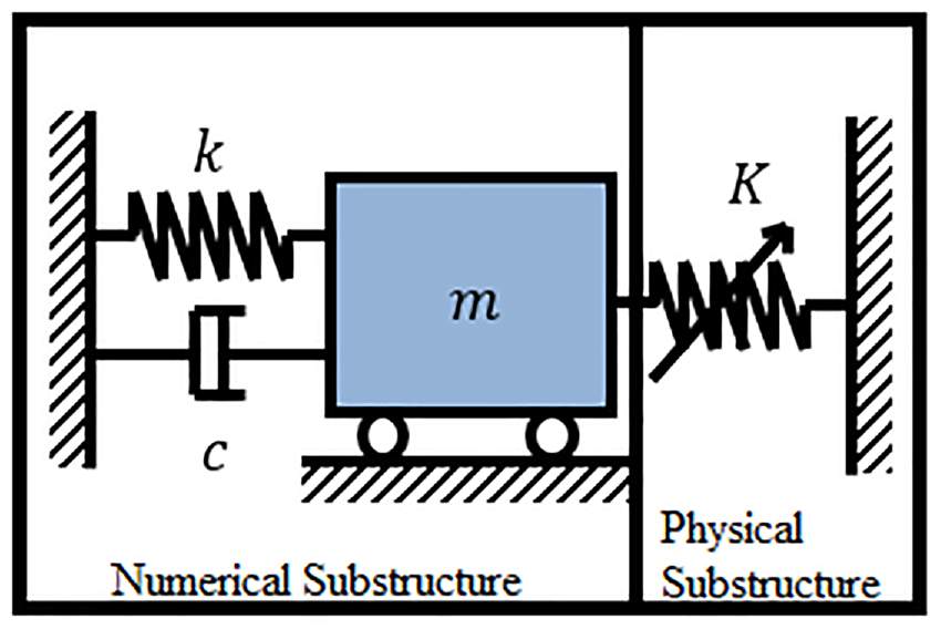
Diagrammatic representation of the emulated system.
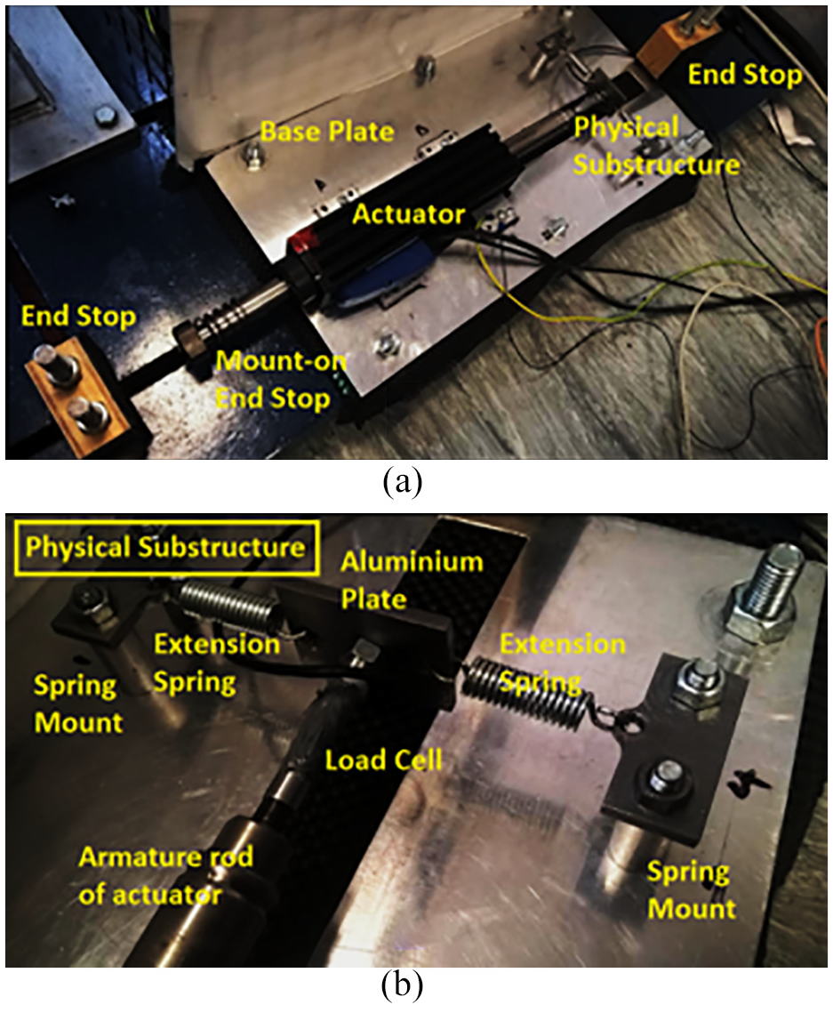
(a) Actuator connected to physical substructure through load cell and (b) view zoomed into physical substructure.
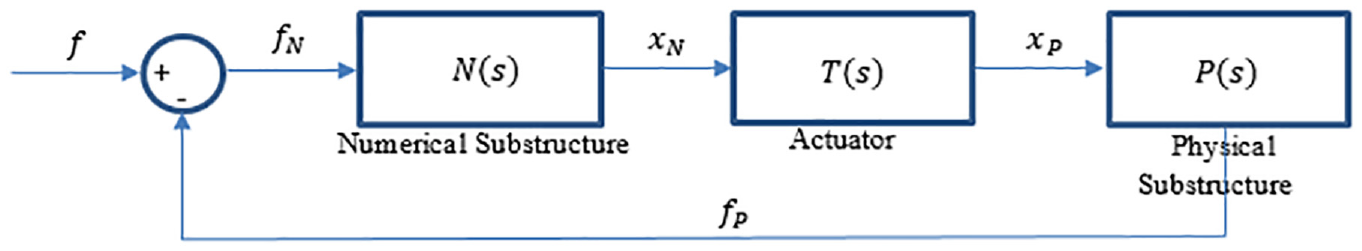
Hybrid test block diagram.
In order to accurately identify the nonlinear stiffness of the physical substructure, the actuator connected to the springs was tested through its full stroke sinusoidally at low frequency (0.1 Hz). The measured force

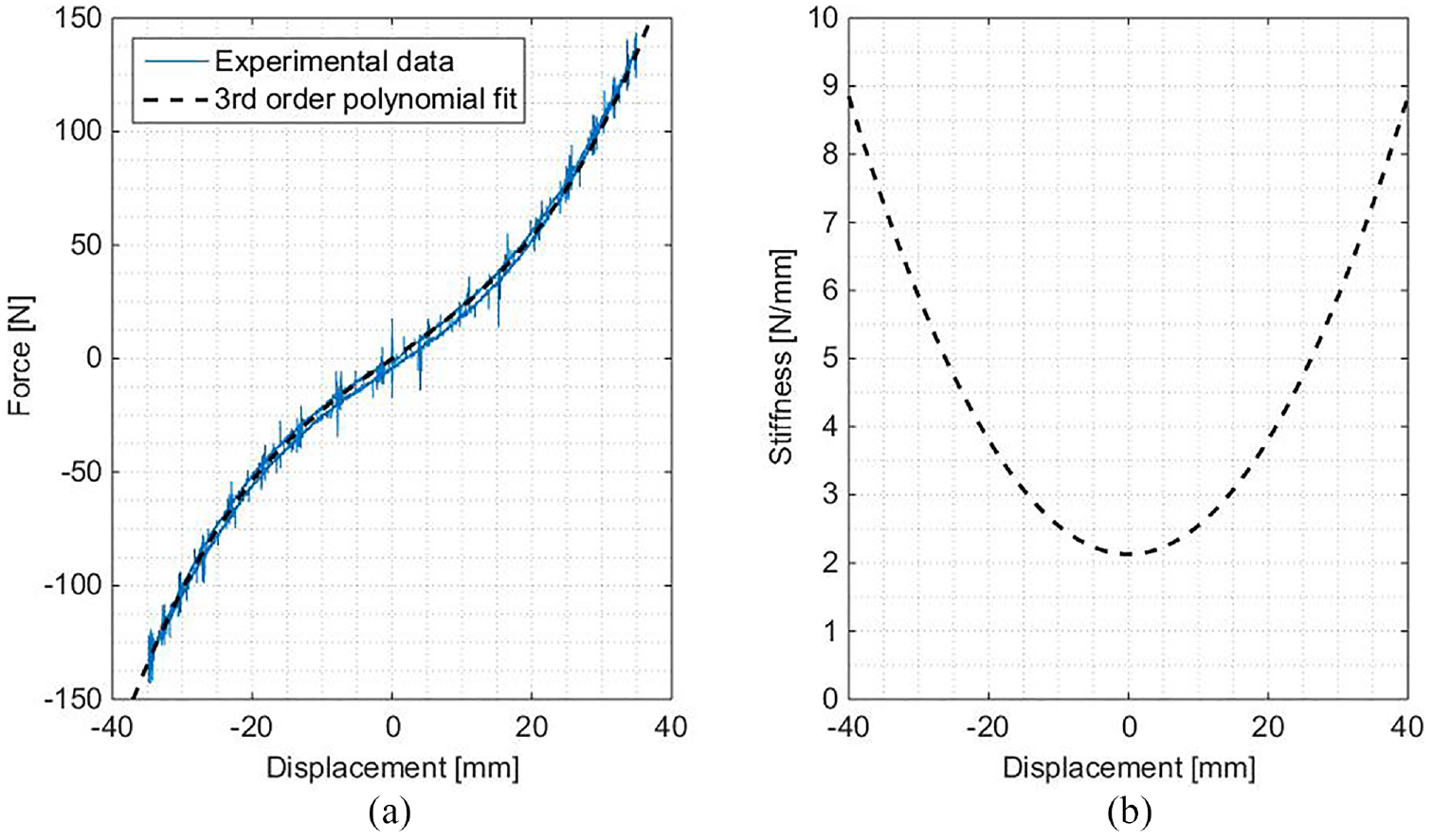
(a) Physical substructure force profile and (b) physical substructure identified tangent stiffness.
Differentiating this expression enables the tangent stiffness of the physical substructure to be expressed as follows
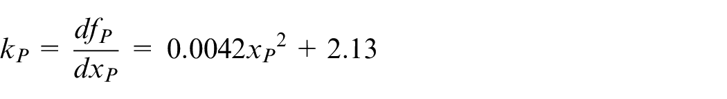
The nonlinear variation of the tangent stiffness of the physical substructure is shown in Figure 5(b) and is seen to increase more than threefold from its zero-displacement value as amplitudes greater than 30 mm are achieved. For small displacements, the stiffness of the physical substructure is approximately 2.13 N/mm. A diagram of the complete hybrid system is shown in Figure 6. All components including the load cell, actuator, real-time controllers, substructures, passivity controller and virtual damper are shown.
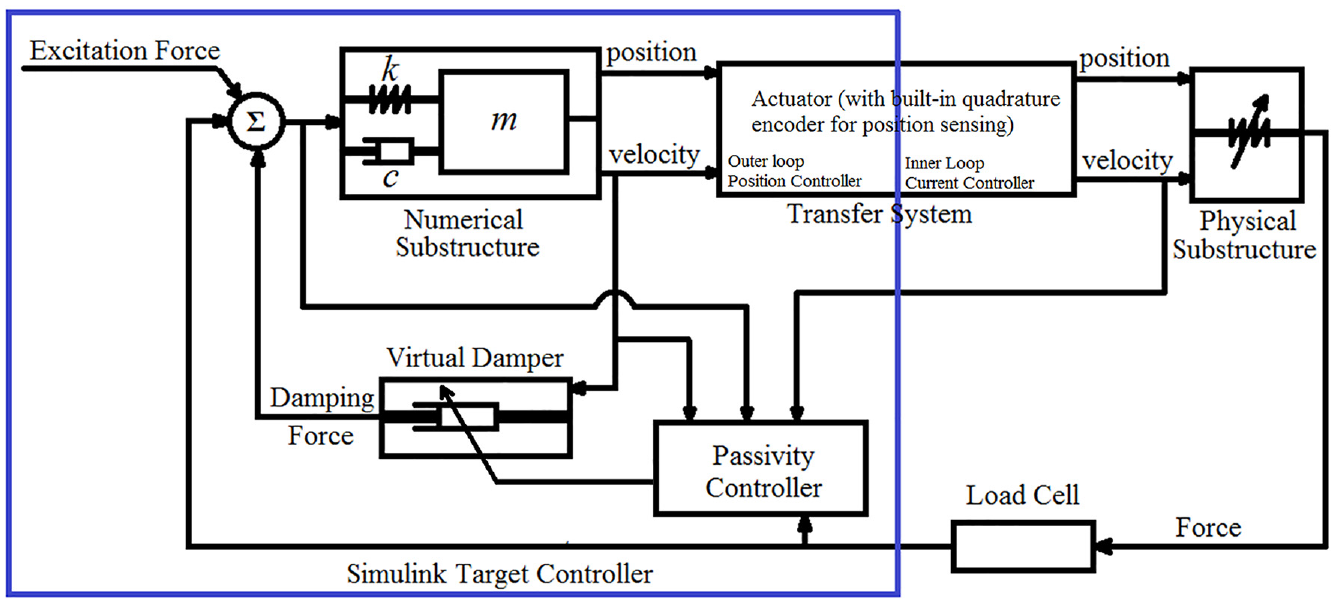
Diagram of passivity-controlled hybrid test system.
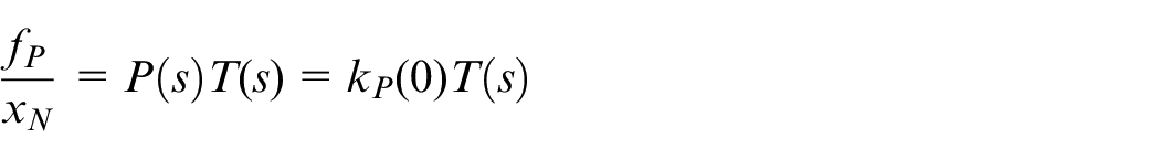
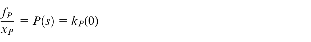
The force acting on the numerical substructure
where
where
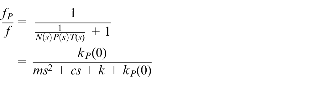
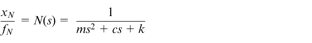
The transfer function relating the physical substructure displacement to the physical substructure force is given by
Hence, the closed loop transfer function relating the excitation force to the physical substructure displacement,
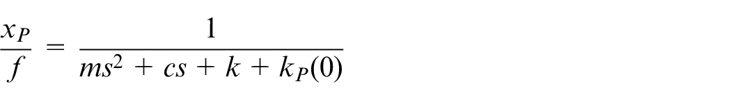
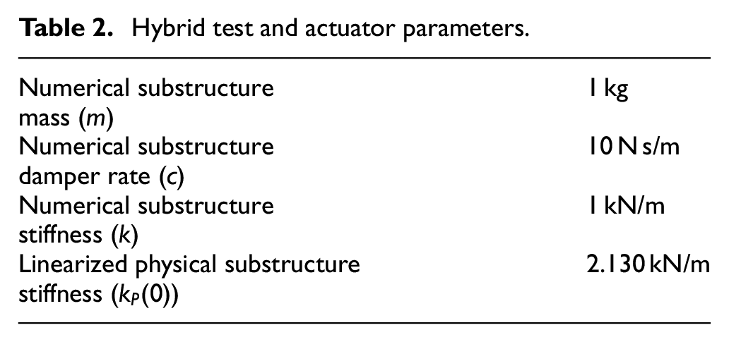
The parameters of the emulated system transfer function are given in Table 2.
Hybrid test and actuator parameters.
Actuator characterization
To identify the transfer dynamics of the hybrid test in the presence of the physical substructure, the actuator connected to the springs was swept from 0.1 to 50 Hz over a period of 50 s at amplitudes 0.5, 1, 1.5 and 2 mm. A fifth-order model of the actuator with nonlinear Coulomb friction was identified for preliminary simulation of the hybrid tests. Figure 7 illustrates the model and actuator responses obtained with and without the use of the friction compensator proposed by Eamcharoenying et al. 26
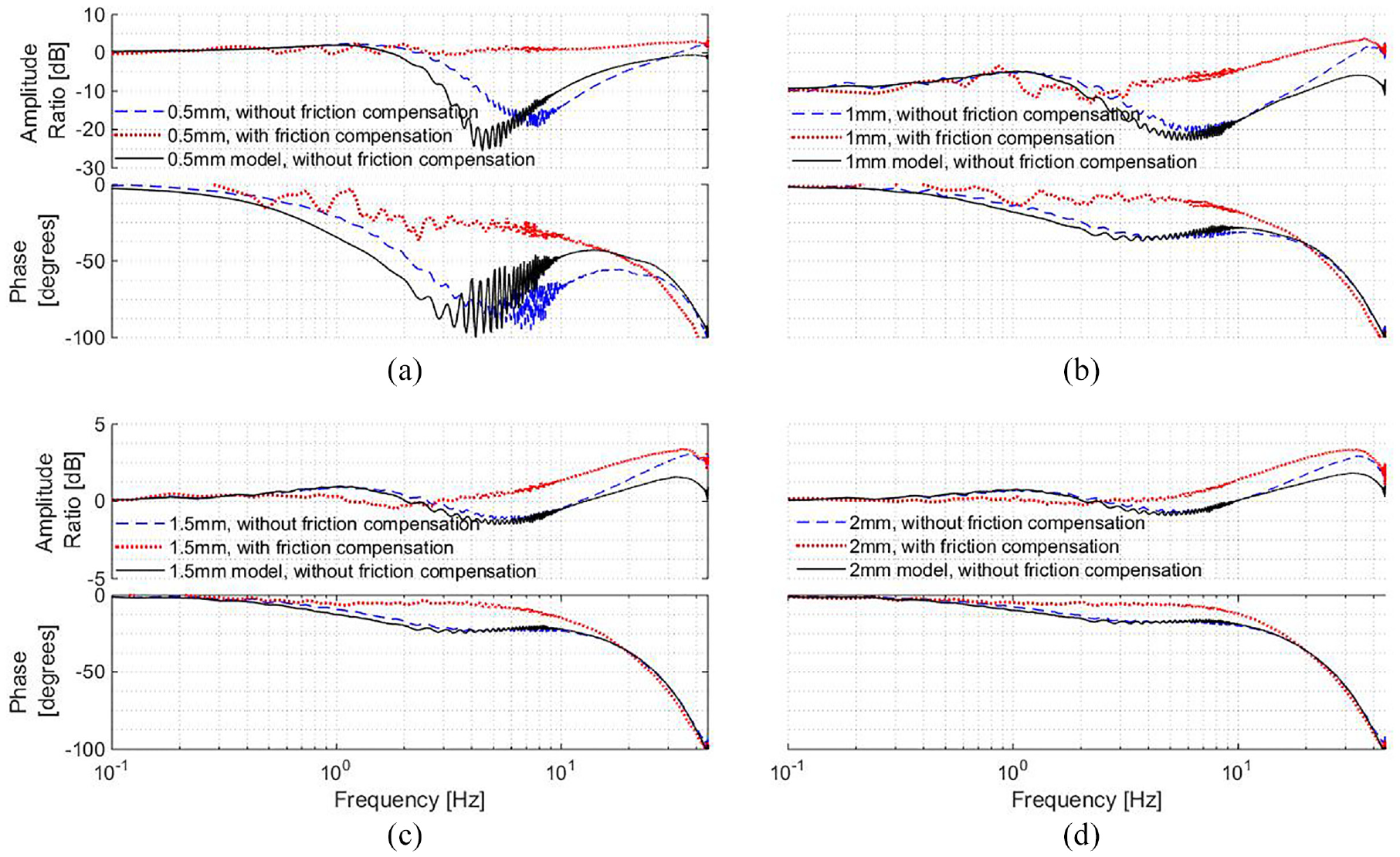
Model and experimental frequency responses of actuator with physical substructure with and without friction compensation at amplitudes: (a) 0.5, (b) 1, (c) 1.5 and (d) 2 mm.
Without friction compensation, the actuator is seen to exhibit significant phase lag particularly in the frequency range of 0.1–10 Hz. This effect is most notable at low amplitudes, such as 0.5 mm, where the velocities are small and the actuation forces are more comparable to the forces of friction. This phase lag is caused by the tendency of the actuator to stick when the driving force is less than the friction force. At high frequency, this effect is less significant due to the high actuation forces exerted to produce the required acceleration. In all amplitudes shown in Figure 7, friction compensation is seen to reduce the actuator phase lag to a noticeable extent. However, complete linearity is not achievable as the phase lag of the actuator swept at 0.5 mm is markedly higher than that seen at 2 mm even with friction compensation. This is to be expected as real friction in the system is complex and cannot be modelled precisely using a simple Coulomb friction model. Therefore, complete eradication of the spurious effects of nonlinear friction in the following hybrid tests cannot be expected particularly at low amplitudes, although friction compensation is applied in all experiments unless otherwise stated, in order to minimize these effects.
Simulation results and discussion
This section presents simulation results to show the expected findings of the application of passivity control. A simple delay of 3 ms is used to model the transfer system dynamics, following the methods in Peiris et al.
10
Two types of physical substructures are assessed; first, a linear stiffness is used as the physical substructure making the entire hybrid system without passivity control as a linear system. Two different stiffness values are used to test how passivity control can affect (1) an otherwise stable system and (2) an otherwise unstable system. Second, the nonlinear stiffening profile seen in Figure 5(a) is tested. The physical substructure stiffness for the linear hybrid tests is denoted as
Figure 8 shows the frequency response for the linear systems, with and without passivity control. The emulated systems are simulated without a delay and without passivity control. The hybrid system with the 20 kN/m physical substructure without passivity control is unstable and is therefore not shown. The results show how passivity control can influence tracking and restore stability. At higher frequencies, however, it cannot compensate the delay itself and this is witnessed in the phase discrepancy between the emulated and hybrid system results. 10
Linear hybrid test responses with passivity control. 10
Step responses for both linear and nonlinear systems are presented in Figure 9, illustrating the effectiveness of passivity control in restoring the performance parameters of the hybrid test, most notably the damped response envelope. A phase delay in the compensated response is evident which corroborates the result seen in Figure 8 indicating that passivity control does not eliminate the lag itself from a hybrid test, only the adverse effects of that lag on the damping properties. 10
Step responses of hybrid test simulation with (a) linear physical substructure stiffness and (b) cubic physical substructure stiffness. 10
Experimental results and discussion
Stability
This section assesses the effectiveness of passivity control in restoring the stability in the nonlinear RtHT described in section ‘Hybrid test’. To understand the effect of the physical substructure in the stability of the hybrid test, the nonlinear physical substructure stiffness is linearized to enable the open loop transfer function of the hybrid test to be analysed. The open loop transfer function of the hybrid test is evaluated using the transfer functions of the numerical substructure, actuator and the physical substructure linearized for a range of physical substructure stiffnesses. The delay margin (phase margin divided by the angular frequency) is plotted against physical substructure stiffness, as shown in Figure 10. It is evident that the hybrid test will be unstable when stiffnesses greater than 2.4 N/mm are achieved, as the delay margin becomes negative. Referring to Figure 5(b), this corresponds to displacements of greater than 8 mm in the cubic stiffening hybrid system presented in section ‘Hybrid test’.
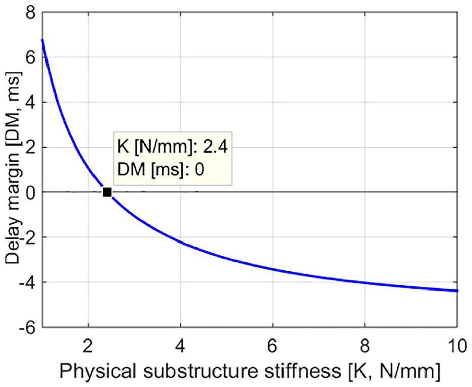
Stability margins of linearized hybrid test for a range of physical substructure stiffnesses.
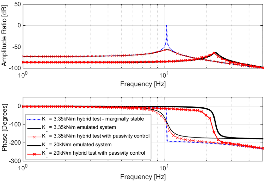
To instigate instability in the nonlinear hybrid test, a force input is required such that physical substructure displacements greater than 8 mm are achieved. Figure 11 illustrates the frequency response of the emulated system and the hybrid test system with different passivity controller gains. The force input to the numerical substructure is measured in Newton while the output displacement at the physical substructure is measured in metre. The response is obtained by sweeping the system sinusoidally at the numerical substructure from 0.1 to 50 Hz in 50 s with an input force amplitude of 15 N. The amplitude ratio of the emulated system approaches −55 dB near resonance which results in physical substructure displacements greater than 8 mm. Hence, the hybrid test without any passivity control is unstable and therefore could not be shown in the figure. The application of passivity control has enabled a stable hybrid test response to be achieved. The passivity controller gain can be tuned to vary the amount of virtual damping in the system. Low gains, such as 1 N s/J m, are seen to result in the best match of resonant frequency, and hence phase, with respect to the emulated system while higher gains, such as 25 N s/J m, result in a better amplitude ratio response at the expense of a lower natural frequency. As before, the lag of the actuator cannot be eliminated using passivity control which only regulates the overall energy flowing in the system. At high frequency, all hybrid test results in Figure 11 are seen to indicate similar levels of phase lag. This is because at high frequencies, vibration amplitudes are low due to the dynamics of the numerical substructure. Therefore, the passivity damping forces too will be low making the system behave similarly to that of a stable hybrid test with no other form of compensation.
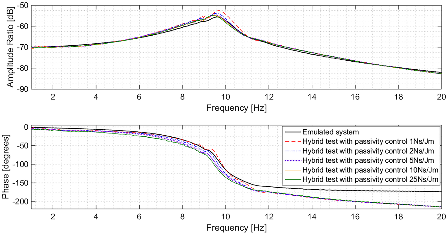
Comparison of the emulated system response with a nominally unstable hybrid test stabilized with passivity control.
The excess energy added by the actuator to the hybrid test in this experiment is plotted against time in Figure 12. Passivity control works to stabilize a system by enabling a means of eliminating the excess energy added by the actuator through virtual damping action. The emulated system represents a perfectly actuated hybrid test and appears in Figure 12 as a line of 0 J.
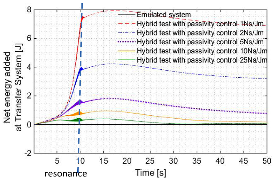
Net energy added to hybrid test by actuator with different passivity controller gains.
Figure 12 indicates that the extra energy added by the actuator can be minimized by increasing the gain of the passivity controller, as higher gains result in greater energy dissipation and hence less excess transfer system energy throughout the test. Minimizing the net energy added at the transfer system will enable the closed loop hybrid test to remain stable. This is true regardless of the linearity of the hybrid test, thereby making passivity control a good extension to a hybrid system required to operate under a range of stable and unstable conditions in a single experiment. Transitional instability between test conditions can be avoided using passivity control as net energy added is regulated. A higher controller gain will result in a more stable hybrid test. However, the controller gain selected must not be excessively high in order to avoid overdamping as this may result in a large phase lag and subsequently high total harmonic distortion and poor tracking. Hence, the controller gain must be chosen adequately high to maintain stability but low enough to maintain acceptable tracking performance. The necessary trade-off in this regard will often be specific to each test case. The most suitable gain for the application must be found by trial and error tuning. A rough assessment of the suitable gains can be made by comparing the passivity damping force with the numerical substructure force. A gain resulting in a passivity damping force much larger than the numerical substructure force is likely to be excessive and this would be an indicator to the user that the gain can be further reduced to minimize distortion while maintaining stability and low oscillation. However, for some applications which may see sudden increases in stiffness through impacts and other nonlinear events, it is desirable to set a higher passivity controller gain to enable a smooth transition between states at the expense of greater nonlinear distortion. There is ongoing research in the development of an algorithm which identifies the optimal passivity controller gain for hybrid tests given user specified weighting coefficients to prioritize stability in relation to nonlinear distortion.
Time domain performance
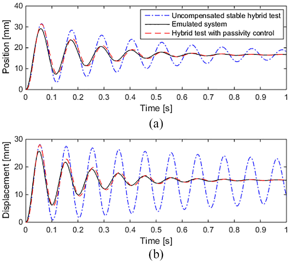
The performance improvements enabled by passivity control in the time domain can be examined by perturbing the numerical substructure of the hybrid test by a step input in force. The force step is applied to the system such that a steady state change in displacement of 10 mm is achieved. The displacement of the physical substructure with and without passivity control is plotted in Figure 13 alongside the displacement of the emulated system simulation to the same step input. Without passivity control, the hybrid test results in sustained limit cycle oscillations. However, passivity control is seen to enable the 2% settling time of the hybrid test to be reduced to 0.674 s which closely matches the expected settling time of 0.684 s seen in the emulated system (error of 1.5%). A small steady state error of 0.2 mm is also seen between the emulated system and compensated hybrid system response, attributed to the inaccuracy in modelling the physical substructure stiffness. As such, it is evident that passivity control can be used to adjust the settling time of a system.
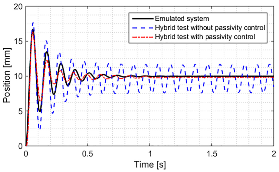
Step response of hybrid test with passivity control.
It is important to note that various passivity controller gains lead to different levels of passivity damping which affect the natural frequency and damping ratio of the hybrid system. Figure 14 illustrates the variation in the impulse response of the hybrid test for a range of passivity controller gains. Friction compensation is not applied in the responses shown in order to ensure that the changes seen in the response are solely due to the action of varying amounts of passivity control. It can be seen that higher gains generally lead to a more damped response with oscillations decreasing in magnitude more quickly. However, for gains above 1 kN s/J m, significant nonlinear distortion is seen in the output. This is to be expected as higher gains result in higher and more volatile virtual damper rates at the passivity controller. The period of the response is seen to elongate when higher gains are used. As before, stability of the closed loop hybrid test is improved through passivity control, while matching the damping properties requires careful tuning, and the frequency and distortion of the response are adversely affected. The optimal controller gain for a system will therefore need to be found on a case-by-case basis.
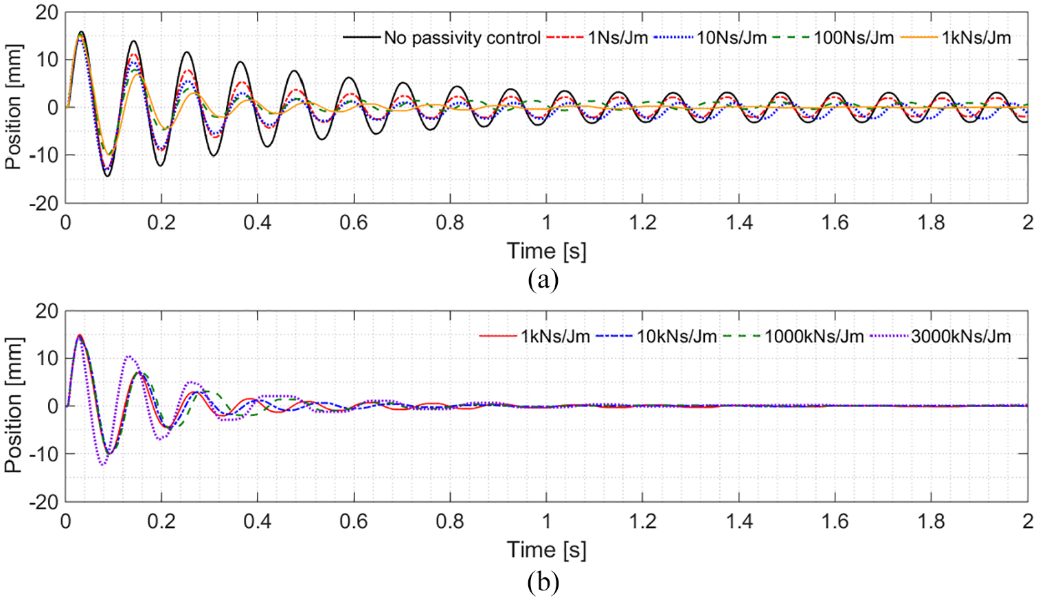
Hybrid test impulse response with different passivity controller gains: (a) low-moderate gains and (b) moderate-excessive gains.
Passivity control compared with model-based compensation
In this section, the performance of a state-of-the-art model-based compensator in a hybrid test will be compared with that of passivity control at low and high frequency. The model-based compensator used is a second-order inverted actuator model, whose design is detailed in section ‘Model-based compensation theory’.
Figure 15 illustrates the response of the identified linear transfer function model against that of the actuator’s response with the physical substructure. The second-order lag is seen to produce a good match with that of the actuator’s amplitude ratio and phase response throughout the frequencies tested, with the largest amplitude and phase error being less than 2 dB and 6°, respectively. The compensated hybrid system is tested with sine wave inputs to the numerical substructure at low and high frequency and the output of the physical substructure is measured and plotted in Figure 16. The response of the emulated system is also shown for comparison. Three types of compensation are used such as friction compensation, second-order lag compensation with friction compensation and passivity control without friction compensation.
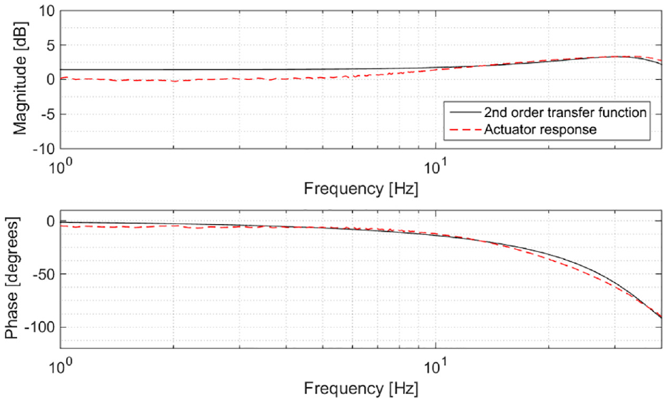
Actuator response plotted against that of the identified second-order transfer function model.
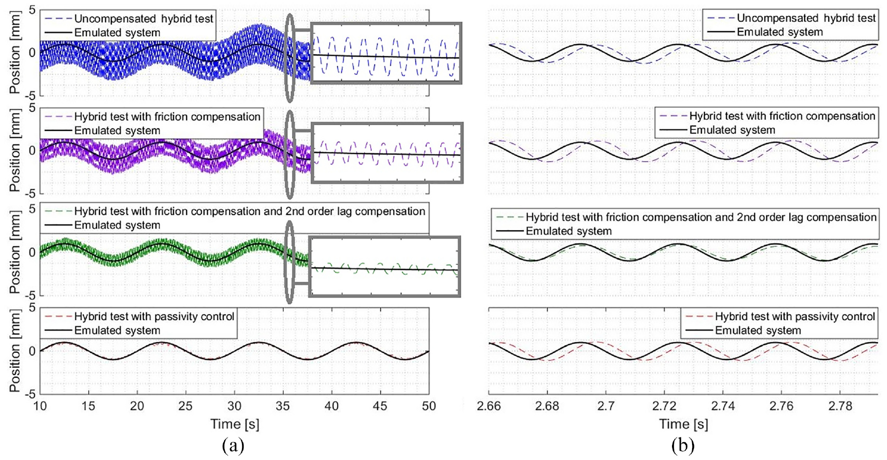
Hybrid test response with passivity control, friction compensation and model-based compensation at (a) low frequency (0.1 Hz) and (b) high frequency (30 Hz).
Figure 16(a) illustrates that at 0.1 Hz, the uncompensated hybrid test system produces limit cycles at its resonant frequency, away from the driving frequency. This is caused by the dominance of friction at low velocities. At low velocities, the forces of friction are comparable in size to the driving forces of the actuator which results in the actuator exhibiting a significant phase lag at low amplitude, seen in Figure 7, eroding stability margins. At high frequency, as shown in Figure 16(b), this limit cycle is not seen due to the dominance of large actuation forces over friction.Friction compensation is seen to result in a 24.5% reduction in the amplitude of the limit cycle compared with that of the uncompensated hybrid test in Figure 16(a). Owing to its simplicity allowing for easy implementation, it is unable to accurately compensate the friction and completely restore linearity as described in section ‘Actuator characterization’. The addition of the second-order model-based compensator is seen to improve the response further with the limit cycle amplitude reducing by 64% compared to the uncompensated case. This is achieved through reducing the lag to improve stability margins. Passivity control, however, is seen to almost completely cancel the spurious oscillation in the response, with the limit cycle amplitude being reduced by 95%. This enables the physical substructure of the hybrid test to follow that of the emulated system with great precision. At high frequency in Figure 16(b), however, the passivity-controlled response exhibits the anticipated phase lag with respect to the emulated system while the model-based compensator successfully mitigates the lag and results in a response which tracks that of the emulated system more accurately. A significant advantage of the passivity controller over the model-based compensator, however, lies in its simplicity and universal application, obviating the need for characterisation of the transfer system. The friction compensated response at high frequency in Figure 16(b) is like that of the uncompensated system response at high frequency since actuation forces dominate over friction when velocities are high.
Importantly, the model-based compensation is effective at reducing phase lag between numerical and physical domains but struggles to adequately compensate for the limit cycles arising from the nonlinearity in the actuator, while the passivity controller is effective at suppressing the spurious limit cycles but cannot remove the inherent phase lag introduced by the transfer system. Thus, the two techniques are complimentary. Figure 17 illustrates the hybrid test responses obtained when combining the two methods. An excitation amplitude of 5 mm is used and the responses are shown together with those of the emulated system. The response with passivity control and lag compensation applied together is seen to provide the benefits of both schemes; Figure 17(a) and (b) illustrates the elimination of limit cycle oscillation due to passivity control while Figure 17(c) indicates tracking improvements due to the lag compensation at high frequency. A phase lag of 35.3° is seen in the response without lag compensation, while the response with lag compensation and the response with passivity control and lag compensation exhibit reduced phase lags of 13.7° in Figure 17(c). As such, it is evident that the use of passivity control with more conventional model-based compensation can provide the user with a system maintaining good stability and tracking simultaneously.
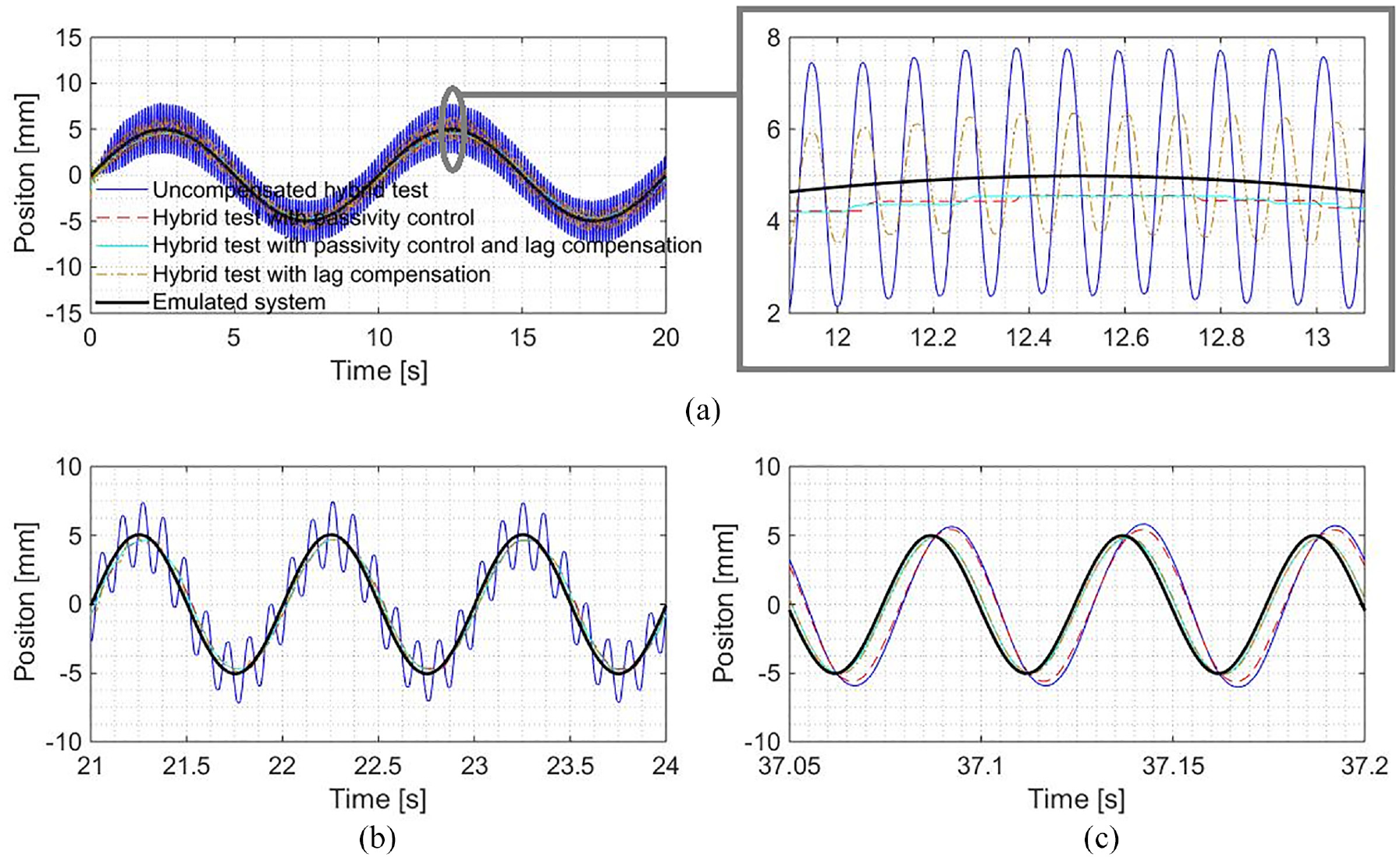
Hybrid test responses with model-based compensation and passivity control at (a) 0.1, (b) 1 and (c) 20 Hz.
Conclusion
This article demonstrates the first application of passivity control to the stabilization of an RtHT. The method was found to restore the stability of a hybrid test in the presence of two distinct types of destabilizing nonlinearities: instability at high amplitudes caused by stiffening of the physical substructure and limit cycles at low amplitudes caused by friction in the actuator itself. In the latter case, it was found that passivity control performed better than model-based methods or simple Coulomb friction compensation alone. Passivity control does not compensate lag directly and must be used to complement other methods where high-fidelity tracking is needed at high frequencies. However, it is extremely simple to implement, requiring no characterisation of the actuator dynamics and only requires tuning of a single gain parameter. Thus, it is anticipated that it will find widespread application where the higher frequency dynamics are less critical to the test and stability is the main requirement. In addition, it has been shown to be valuable when used in conjunction with delay- and lag-compensation schemes, where it can compensate for model uncertainties and stabilize tests throughout transient events such as stiff impacts. This method is expected to play a key role in the development of the next generation of hybrid test equipment, in turn in facilitating rapid development cycles in industrial design.
Footnotes
Appendix 1
Declaration of conflicting interests
The author(s) declared no potential conflicts of interest with respect to the research, authorship, and/or publication of this article.
Funding
The author(s) disclosed receipt of the following financial support for the research, authorship, and/or publication of this article: This work has been supported through funding from the Engineering and Physical Sciences Research Council (Grant Reference No. EP/N032829/1).