
Abstract
The wearable powered exoskeleton is a human-robot cooperation system that integrates the strength of a robot with human intelligence. This paper presents the research results into a powered hip exoskeleton (PH-EXOS) designed to provide locomotive assistance to individuals with walking impediments. The Bowden cable actuated exoskeleton has an anthropomorphic structure with six degrees of freedom (DOF) in order to match the human hip anatomy and enable natural interaction with the user. The mechanical structure, the actuation system, and the interaction kinematics of PH-EXOS are optimized to achieve preferable manoeuvrability and harmony. For the control of the exoskeleton, a real-time control system is established in xPC target environment based on Matlab/RTW. A Cascaded PID controller is developed to perform the trajectories tracking tasks in passive control mode. Besides, based on the pressure information on the thigh, a fuzzy adaptive controller is developed to perform walking assistance tasks in active control mode. Preliminary treadmill walking experiments on a healthy subject were conducted to verify the effectiveness of the proposed device and control approaches in reducing walking effort.
Keywords
1. Introduction
The powered exoskeleton is a type of wearable robot system working in parallel with human limbs and combining the strength of a robot with human intelligence [1]. It can effectively improve human strength, endurance, and locomotion in various environments. Research on the exoskeleton started in Europe, North America and Japan about 50 years ago and is now applied in many industrial applications ranging from medicine to the military [2]. Specifically, for lower-limb exoskeletons, applications include walking assistance for elderly individuals, rehabilitation of patients with physical disabilities [3], and power amplification for soldiers. Currently, as the population continues to age, more and more individuals suffer from mobility difficulties and disorders [4]. The use of a powered exoskeleton is an effective solution to help these disable people regain their locomotion and live without the physical assistance of therapists [5].
For the initial motivation of developing a lower-limb exoskeleton, the control system design is a significant challenge in providing functional locomotion. During walking assistance, the exoskeleton is required to automatically follow human movement and provide additional torque at the joints of the user and, as a consequence, decrease metabolic energy consumption. In order to achieve natural human-robot coordination, it is necessary for the robotic control system to recognize the implicit intention of the user from interaction behaviours or biological signals. Thus, the design of the sensing system should be taken well into consideration. Many kinds of sensors, like the encoder, potentiometer, accelerometer, gyroscope, force sensing resistor (FSR) sensor, muscle hardness sensor and electromyography (EMG) signal sensor have been applied in the control system to achieve effective assistance performance [6].
Tsukuba University in Japan developed an assistive exoskeleton named HAL (hybrid assistive limb) for supporting physical disabled individuals by analysing the disability percentage and amplifying the joint torque of wearer [7]. Harmonious gear reducers and electrical servo motors were mounted at the hip, knee and ankle joints as the actuators [8]. EMG sensors, gyroscopes, and ground reaction force sensors were used to detect motion intent and operate the device in two modes: an EMG-based mode and a walking-pattern-based mode [9]. The Berkeley lower extremity exoskeleton (BLEEX) is a load-bearing and energetically autonomous exoskeleton developed at the University of California [10]. BLEEX used linear hydraulic actuators to power the rotary joints. The payload forces were transferred to the ground via the exoskeleton [11]. A sensitivity amplification controller was designed by using the inverse dynamic of the robot as a positive feedback to increase the closed loop system sensitivity to wearer's forces and torques, requiring no direct measurement from the user [12]. Massachusetts Institute of Technology (MIT) developed a quasi-passive lower-limb exoskeleton that can apparently improve the load carrying capacity of the wearer without any actuators [13]. Passive ankle and hip springs were used to store and release energy based on the walking kinematics and kinetics of humans. A knee variable damper was utilized to reduce muscular effort and provide the necessary resistive torque. The MIT exoskeleton was controlled by analysing the sensory information of full-bridge strain gages and potentiometers [14]. Nanyang Technological University designed a wearable lower-limb exoskeleton named LEE for travelling long distances with heavy loads [15]. LEE consists of an inner exoskeleton to measure the movements of an operator and an outer exoskeleton to support the payload. A novel foot-unit was developed to measure the zero moment points (ZMP) of the operator and exoskeleton simultaneously. The balancing quality of the overall system was adjusted by a trunk compensation device based on the ZMP information [16].
In this paper, a brand-new powered hip exoskeleton (PH-EXOS) is presented, with the objective of assisting the lower limb motion of the individuals having walking impediments. The mechanical structure of PH-EXOS is designed to be anthropomorphic in order to provide natural walking assistance for the user. AC servo motors and flexible Bowden cable transmission systems are incorporated into PH-EXOS, leading to low inertia, compact structure, and high performance actuation. The human-robot interaction kinematics are analysed and, meanwhile, the kinematic mismatch is compensated by a slider unit. Two control methods are applied to the exoskeleton system: 1) the passive control method with a cascaded PID controller to perform trajectory tracking experiments; 2) the active control method with a fuzzy adaptive controller to perform walking assistance experiments. Finally, treadmill walking experiments are carried out to verify the effectiveness of the proposed control algorithms, and the experimental results are reported and discussed.
2. Design of the Exoskeleton
The purpose of developing PH-EXOS is to provide sufficient walking assistance in human locomotion. In order to perform walking tasks effectively, the structure of the exoskeleton is designed to be kinematically similar to the anatomy of the human hip and thigh. Besides, the human-robot interaction kinematics are analysed and optimized to enable natural walking.
2.1 Mechanical Design
The architecture and major components of PH-EXOS are shown in Figure 1. The exoskeleton has two passive DOF (internal/external, and abduction/adduction) and one active DOF (flexion/extension) at each hip joint. Figure 2 shows the exploded diagram of hip joint design. Since the motion ranges and power consumptions in hip joint abduction/adduction, and internal/external movement directions are relatively small, a passive universal joint is installed to satisfy the motion requirement in this two DOF. Each active joint of PH-EXOS is actuated by a YASKAWA servo AC motor (SGMAH-01AAA41, reduction ratio-40:1) via a flexible Bowden cable transmission system. The driving motors are mounted behind the backpack frame having a strong structural rigidity. Such a structure allows the hip assembly to retain the centre of gravity close to the wearer and avoid interference between motors and swinging forearms. All the joint spindles are installed in precision bearings in order to reduce rolling friction and abrasion. The backpack frame is constructed in the shape of the letter ‘U’ so as to adjoin the pelvic bone and vertebrae bone and as a result, allow the exoskeleton to be mounted to the waist of the wearer. The width of the backpack frame can be adjusted along the backside of the sacroiliac joint by loosening and tightening the threaded bolts in the slide slots, making the exoskeleton suitable for users with different parameters. A cushioning pad is provided to the backpack frame to avoid direct contact of the exoskeleton with the body of user and so satisfy walking comfort. Most of the mechanical components are made of duralumin material and the total weight of the exoskeleton, including the actuators, is about 3.5 kg. The thighs of the exoskeleton are connected to the user with two fastening Velcro straps near the distal end of linkages and are wrapped around the thighs of the user. Four FRS sensors (FlexiForce-A301) are installed between the straps and thighs to measure the human-robot interaction forces and estimate the motion intention of the user. The position of each active joint is measured with an angular displacement potentiometer (WDJ22A) enclosed in the joint structure. The driving motors are controlled with the algorithms developed based on the output signals of these sensors.
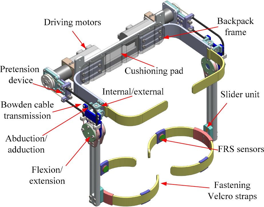
The architecture and major components of PH-EXOS

The exploded diagram of hip joint design
2.2 Bowden Cable Actuation System
Figure 3 is an explanatory drawing showing one of the active joints of PH-EXOS actuated by a remote motor through a Bowden cable transmission system, which mainly consists of a pair of helical tension springs as the outer sheaths, and a pair of steel wires as the inner cables. Bowden cable actuation, constructed as a rotary joint to transfer assistive power from the actuator to the output side, has been widely used in robot design because of its simplicity, dexterity, and remote transmission [17]. The cables are fixed to the pulleys at the proximal side and distal side in a pull-pull configuration, ensuring that the robotic joint can rotate consistently with the motion of the actuator in both directions. When the inner cable is pulled at one end, the pulling force can be delivered to the other distal end through the outer sheath. It should be noted that the force transmission characteristics are concerned with the total sheath bending angle, sliding friction coefficient, and the system preload [18]. An advantage of Bowden cable actuators is that it removes the driving motors from a human body and, thus, helps to achieve a lightweight, low consumption and high performance system [19]. The pretension device mounted at the proximal side can be utilized to adjust the initial pretension force by tightening or loosening the preloaded bolts and avoid system slacking due to cable elasticity.
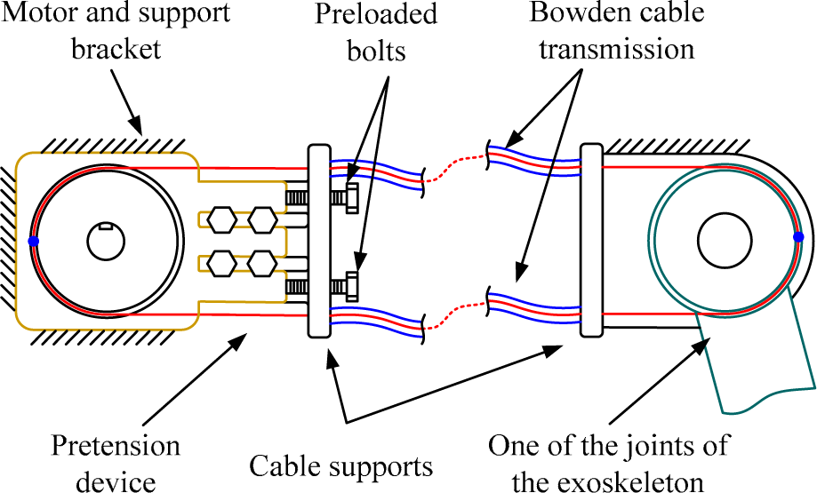
The schematic of the Bowden cable actuation system
2.3 Interaction Kinematics
In walking assistance application, the power exoskeleton is required to smoothly interact with the user and provide a full range of natural movement. The human hip is constructed as a ball and socket joint with three DOF. Note that the misalignment existing between the centre of human hip joint and the rotation axis of the exoskeleton would cause uncontrollable forces imposed on the user. However, it is unreasonable to three-dimensionally maintain the position of the human hip joint coincident with that of the exoskeleton due to several limitations, such as complicated mechanical structure, limited range of motion, and unavoidable singularities [10]. For this reason, the connection mechanism between the thigh of the exoskeleton and the human limb is expected to be able to automatically compensate the kinematic mismatch and eliminate the safety hazard as well as discomfort during physical human-robot interaction. In the mechanical structure of PH-EXOS, the joint axis of flexion/extension movement is designed to be coincident with the human hip joint while the other two DOF are not. According to the mechanisms of BLEEX [10] and the exoskeleton developed by MIT [13], when compared with the abduction/adduction movement, the kinematic mismatch caused by the internal/external rotation movement is relatively small and thus can be eliminated. Therefore, the actual offsets that exist between the human body and the exoskeleton when the user performs an abduction/adduction movement is analysed as follows.
The schematic for explaining human-robot interaction kinematics is shown in Figure 4. The thighs of the exoskeleton and human are modelled as two links, O1A1, and O2B2, which are parallel to each other in the initial state; O1 and O2 denote the revolute abduction joint of the exoskeleton and the ball and socket joint of the human; A1, and B1 are the initial connection positions between robot and human; θ is the angle between O1O2 and the vertical direction; a is the abduction/adduction angle of human, which stays positive in the abduction direction and negative in the adduction direction; Δa is the deviation angle between the exoskeleton and human limb due to the misalignment of the rotation axis; O1A1, and O2B2 are the final positions of the thighs of the exoskeleton and human; A1B1, and CB2 represent the rigid connection mechanism, which is vertical to the human limb and has a constant length. It should be noted that point C is not coincident with point A2 in the final state: it slides along the longitudinal direction of the thigh of the exoskeleton by a distance of |A2C|. If the connection mechanism is fixed to the exoskeleton at point A2(A2), undesired interaction forces will be created during motion, since the length of the connection mechanism is elongated under the external tension (i.e., |A2B2| is larger than |A1B1|).

The schematic for explaining the difference in motion between the human body and the exoskeleton resulted from dissimilar centres of rotation
Therefore, the connection mechanism is designed to be a slider unit in order to compensate kinematic offsets and reduce interaction forces. The proposed slider unit comprises an outer guide groove and an inner slider telescopically connected to each other, just as shown in Figure 5. Two compressed coil springs are disposed inside the outer guide groove for the purpose of increasing the flexibility and compliance of the human-robot interaction. The fastening Velcro strap mounted inside the strap holder is fixed to the inner slider so as to transfer the driving force to the human body and, more importantly, adjust the connection position to a suitable point on the robot thigh once the abduction/adduction angle is changed. The available compensation amount of the slider unit is larger than the maximum sliding length during walking, which is discussed as follows.

Close-up view of the slider unit
For simplification, we redefine the links shown in Figure 4 by Eq (1).

According to the triangle cosine theorem and the geometric relationship presented in Figure 4, the sliding distance |A2C| can be calculated through Eqs (2–5).


where L1, L2 L3, L4 and θ are all constant values. These parameters are available according to the model of the virtual prototype of PH-EXOS. It can be seen that the sliding distance is related to the abduction/adduction angle of human (i.e., a). The maximum abduction/adduction angle during walking can be found by examining the clinical gait analysis (CGA) database of Hong Kong Polytechnic University [20]. Finally, the maximum sliding distances in both directions can be obtained. The total sliding distance is the sum of each maximum sliding distance, which should be compensated by the slider unit. The parameters of the interaction kinematics are all shown in Table 1.
The parameters of the interaction kinematics between human body and exoskeleton

3. Hardware of the Control System
The hardware architecture of the control system for PH-EXOS is presented in Figure 6. The control hardware mainly consists of two industrial personal computers (TPC-610H, Advantech Inc.) working as the host computer and the real-time target, FRS sensors installed at the thigh braces to measure the human-robot interaction forces and estimate the motion intention of the user wearing PH-EXOS, potentiometers mounted at the distal end of the Bowden cable transmission system to measure the joint angle and velocity for each active joint and several motion controllers. A real-time control system established in xPC target environment based on Matlab/RTW. xPC target is capable of running critical programs all the time and providing a convenient software environment for the system developer to test hardware performance with different control algorithms. The signals of the sensors, amplified by a transistor made power amplifier, are acquired and processed via an A/D data acquisition card (PCL-818, Advantech Inc.). For the command generation, a real-time target computer is utilized to analyse all the feedback information and send the appropriate commands to each motor controller in discrete time. A D/A board (PCL-726, Advantech Inc.) is used to provide an analogue output signal in the system. The control schemes for walking assistance are generated in a Simulink environment and applied to the exoskeleton system with a sampling rate of 10 kHz.

The hardware architecture of the control system
4. Control Methods and Experiments
In order to realize the desired functionality of the walking assistance device, a cascaded PID controller and a fuzzy adaptive logic controller are developed for the passive and the active motion control of PH-EXOS, respectively. In the passive control mode, the assistance movement is externally imposed to the hip joint of the user according to a predefined gait trajectory. On the contrary, the power exoskeleton is capable of estimating the motion intention and applying active support to the user in the active control mode.
4.1 Cascaded PID Control
As the first step, the passive walking algorithm is applied to the real-time control system using a cascaded PID controller, which is able to rapidly respond to the external disturbances and promote system performance in trajectory tracking. The block diagram of the proposed controller is shown in Figure 7. The planning trajectory of each active joint is in accordance with the kinematic CGA data. The hip joint angle in the flexion/extension direction basically follows an approximate sinusoidal trajectory. All the driving motors are run in velocity mode. Angular potentiometer readings that indicate the actual hip joint position are compared with the planning trajectory, and then the difference value is sent into the outer loop PID controller to control the movement of the motor. A Bessel low pass analogue filter with a cut-off frequency of 60 rad/s is used in the controller to filtrate the interfering signal. The output of the outer loop PID controller and the comparison error of the actual and desired angular velocity are all sent into the inner loop PID controller to modulate the motor speed. The maximum changing rate of the motor rotation is restricted by a saturation module for the purpose of ensuring the safety of the user.
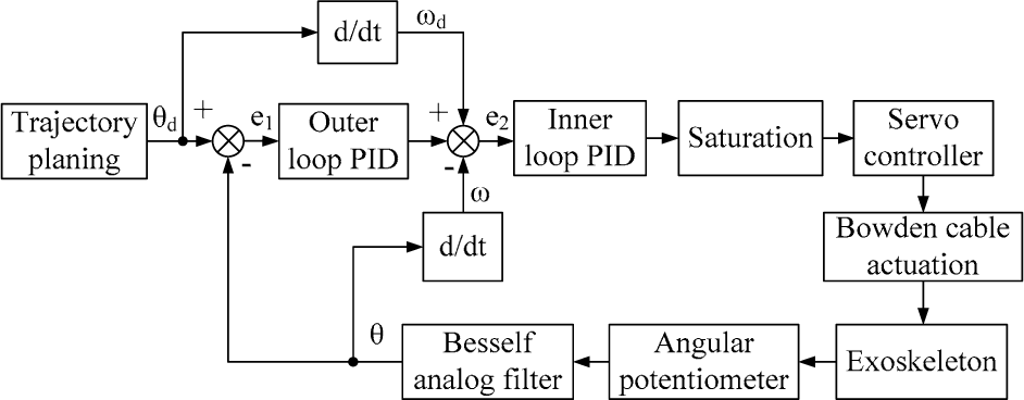
The block diagram of the cascaded PID controller implemented on each joint of the exoskeleton
In the passive control experiments, a healthy subject (weight: 60 kg height: 1.70 m) was required to exercise on a treadmill with a speed of 1.3 m/s, as shown in Figure 8. The gait cycle time of the desired trajectory implemented at each hip joint was 2 s. The parameters of the cascade PID controllers were carefully turned by trial and error in order to improve the control accuracy and the working performance of the system. The relatively favourable parameters are shown in table 2. Desired and actual hip joint trajectories in one arbitrary gait cycle are presented comparatively in Figure 9. As can be observed, the desired trajectories are almost coincident with the actual trajectories. The average tracking errors are less than 2 degrees at both of the right hip joint and left hip joint. It is worth noting that, due to the Bessel analogue filter module, there is about 0.07 seconds delay in the trajectory tracking experiments, which are the main tracking error source. However, the tracking errors and time delay in the exoskeleton system are relatively acceptable to the realistic walking assistance application. During the passive experiment process, the user felt comfortable walking with the exoskeleton. The obtained results verify that the proposed device can smoothly interact with human motion and the misalignments between the robot and the human limb can be well compensated.
The parameters of cascade PID controllers

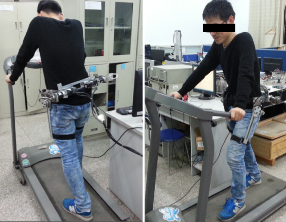
Treadmill experiments with the hip exoskeleton

Comparisons of the desired and actual hip joint trajectories in one arbitrary gait cycle, (a) the right hip joint and (b) the left hip joint
4.2 Fuzzy Adaptive Control
The passive control algorithm that regulates the robot joint position to follow the predefined trajectory is mainly applied in the lower rehabilitation system for patients with motor dysfunction. However, such a position-based control approach is not suitable for walking assistance application due to several realistic problems. Firstly, the human gaits vary greatly depending on factors such as anthropometry, weight, and age. Therefore, it is difficult to predefine the motion trajectories which well match the walking gaits of different individuals. In addition, it is uncomfortable for the user to passively walk with the exoskeleton, as the human movement intention and the human-robot interaction are all neglected in this control mode. The exoskeleton may disrupt the natural gait of the user and, more seriously, lead to a falling accident. Finally, since the motion trajectory is predetermined, the user is not allowed to adjust the step length and gait period during the walking process, which is inconvenient for practical application. Therefore, it is necessary to develop an active control algorithm, taking into account the walking intention of the user and providing effective assistance suitable to arbitrary human gait features.
According to the biomechanical characteristics of the lower-limb muscles, the human mechanical power is generated by muscular contraction and expansion during locomotion, which can also cause changes in muscle length and stiffness [22]. Inspired by this fact, in order to estimate the motion intention of each hip joint, two novel sensory units are installed at each fastening Velcro strap to measure the pressure signals generated by the rectus femoris muscle and biceps femoris muscle, as shown in Figure 10. The pressure signals change with different hip joint postures. Figure 11 shows the close-up view of the human-robot interaction sensory unit, which mainly consists of a FRS sensor for pressure measurement and an elastic support connected to the fastening strap. Besides, for the purpose of enlarging the contact pressure and reducing the measurement error, the FRS sensor is stuck to a rigid connector with epoxy glue. The cross-sectional area of the connector is consistent with the effective detection area of the sensor. The location of the FRS sensor can be adjusted along the longitudinal direction of the strap under slack state. On the contrary, the location is fixed when the strap is tightened up.

The attachment positions of the FRS sensors used to recognize the movement intention of the user

Close-up view of the interaction sensory unit
Before the active control algorithm was developed, a free walking experiment was conducted to analyse the correlation between pressure information and human motion. The subject was required to walk on the treadmill with a speed of 1.5 m/s without assistance from the exoskeleton, as shown in Figure 12. The exoskeleton was used as a motion detecting device to record the contact force signals and the joint angle trajectories during the tests. Figure 13 shows the comparison of the left hip joint angle versus the pressure of each FRS sensor in 10 s. From the experimental results, we can see that the changing tendency of the hip joint angle is basically consistent with those of the front contact force and the rear contact force. In addition, it should be noted that the muscle generates muscular force before the hip joint action and the signal of each FRS sensor precedes the joint movement by about 0.2 seconds. The leading time is significantly important for motion recognition and real-time control of the assistance system, since the unavoidable time delay caused by the Bowden cable actuation system and the analogue filter module needs to be compensated in the motion-prediction-based control pattern.

Free walking experiments with the exoskeleton working as a measurement device

Comparison of the hip joint angle and the pressure of each FRS sensor
The pressure values during the walking process are greatly influenced by the initial preload of the fastening strap, which is different each time the user wears the exoskeleton. Therefore, it is more rational to make use of the change rates of the measured pressures rather than the actual pressure values for controlling the driving motor running in velocity mode. The comparison of the hip joint velocity versus the change rate of pressure of each FRS sensor is shown in Figure 14. This paper proposes a preliminary control algorithm for active assistance. The block diagram of the active controller is represented in Figure 15. The desired hip joint velocity can be estimated as follows:

Comparison of the hip joint velocity and the change rate of pressure of each FRS sensor

The block diagram of the active control algorithm implemented on each joint of the exoskeleton

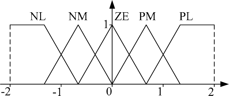
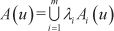
where Ffront and Frear denote the pressure values on the front side and the rear side of the fastening strap, Kfront and Krear are the parameters used to adjust the scale of joint velocity. The control of each hip joint is independent. To further improve the assistance performance, a fuzzy adaptive controller is developed based on the Mamdani model and applied to the control system for the online turning of the differential gain coefficients, which contain significant uncertainties under various operational conditions. The fuzzy turning rules are indicated in table 3 and table 4 with the change rates of the measured pressure as the inputs and the adjusted values (i.e., ΔKfront and ΔKrear) as outputs respectively. The fully populated rule base has 25 input rule combinations. Each input rule combination activates one output action. The characters NT, NM, ZE, PM, and PT stand for negative large, negative medium, zero, positive medium, and positive large. The derivation of fuzzy control rules is determined by analysing the behaviour of the walking process [23]. Triangle and trapezoid membership functions are applied for the inputs and outputs in this work, as illustrated in Figure 16 and Figure 17. The input and output linguistic variables are defined in the domains of Din=[2,2] and Dout=[−1,1]. The centre of gravity (COG) method is employed to defuzzify the membership functions. The defuzzification function is represented as follows:

where ΔK is the defuzzified output; n is the number of the output quantization levels; A(uj) is the firing strength of the inferred fuzzy set corresponding to the support value uj.
The fuzzy control rules for ΔKfront

The fuzzy control rules for ΔKrear

The input membership functions of the fuzzy adaptive controller for dF front /dt and dF rear /dt

The output membership functions of the fuzzy adaptive controller for ΔK front and ΔK rear
Furthermore, based on the Zadeh fuzzy synthesis method, the firing strength value can be calculated as:

where m is the number of activated fuzzy rules; λ i denotes the weight of the i th rule to the fuzzy control action; Ai is the output fuzzy set of the i th rule; P1 i and P2 i represented the fuzzy sets for dFfront/dt and dFrear/dt;
Finally, the appropriate parameters of the overall system are moderately selected in accordance with the hip joint movement. The cut-off frequencies of the Bessel low pass analogue filters are all set to 60 rad/s to refine the human-robot interaction forces. The saturation module is used to limit the maximum motor speed for safety concerns.
The effectiveness of the proposed active control algorithm was investigated by experiments. The subject was fitted with PH-EXOS and walking tests conducted on the treadmill with a speed of 1.5 m/s for 10 s, similar to the free walking experiment. The free walking data of hip joint trajectories and pressure variations were used as references to evaluate the assistance performance in active control experiments. The comparison of the motion trajectories with and without assist are presented in Figure 18. We can see that the gait period and step lengths basically remain unchanged with the same walking speed. Figure 19 and Figure 20 show the pressure signals of the front and rear FRS sensors with and without assist, respectively. It is observed that the pressure signals with assist are smaller than those without assist. More specifically, the average value of pressure decreases about 22.4% in the front FRS sensor and, meanwhile, 38.7% in the rear FRS sensor. According to the available literatures, Kyoungchul Kong [5] and Yamamoto Keijiro [26] have developed two different sensors to measure the pressure and muscle stiffness of the thigh and proved there to be a positive correlation between the hip joint torque and pressure signal at the thigh. Therefore, the experimental results demonstrate that the proposed hip joint exoskeleton succeeds in providing assisting forces to the user and reducing muscular power consumption during walking.

Comparison of the hip joint trajectories with and without assist

Comparison of the front pressures without and with assist

Comparison of the rear pressures without and with assist
5. Conclusion and Future Works
This paper presents a novel 6 DOF hip joint exoskeleton named PH-EXOS for walking assistance. Each active joint of the exoskeleton is actuated by a flexible Bowden cable actuation system, which plays a significant role in providing remote power transmission and simplifying the structure design. The major mechanical structures of PH-EXOS and the Bowden cable actuation system are described. The interaction kinematics problem is taken into consideration to satisfy user comfort and human-robot harmony. A cascaded PID controller and a fuzzy adaptive logic controller are developed based on a real-time control system for the passive/active motion control of PH-EXOS. The performance of each control algorithm has been tested on a subject conducting treadmill walking experiments. The results suggest that the PH-EXOS system can effectively follow the predefined trajectories in the passive control mode and, on the other hand, reduce the muscular power consumption of the user in the active control mode. Future works will be devoted to integrate the control system and power generation unit into PH-EXOS and, finally, achieve a completely independent walking assistance device for practical application. In addition, a complete lower limb exoskeleton capable of providing walking assistance to the hip, knee and ankle will be developed based on PH-EXOS.
Footnotes
6. Acknowledgements
This research has been supported by the Fundamental Research Funds for the Central Universities (CXZZ13_0085), the Scientific Research Foundation of Graduate School of Southeast University (YBJJ1427), and the China Nation Nature Science Foundation under grant 51175078 and 50875044.