
Abstract
This paper presents the design of a new monolithic two-axis electrostatically actuated MEMS microgripper with integrated capacitive position and force sensors working at the micro-scale level. Each of the two jaws of the microgripper possesses two degrees-of-freedom (DOF) and is capable of positioning in both x-and y-axes. Unlike existing works, where one gripper arm is actuated and other one is sensed, both arms of the proposed microgripper are actuated and sensed independently. A sensing scheme is constructed to provide the position and force signals in the noncontact and contact phases, respectively. By applying a 120V driving voltage, the jaw can provide 70 μm x-axis and 18 μm y-axis displacements with the force of 190 μN. By this design, the real-time position and grasping force information can be obtained in the dual sensing mode. Both analytical calculation and finite-element analysis (FEA) were performed to verify the performance of the proposed design. A scaled-up prototype is designed, fabricated and tested through the experiment to verify the structure design of the microgripper.
Introduction
In recent years, microgrippers have been widely applied in microassembly and micromanipulation tasks. Microgrippers act as a key element for handling fragile objects, such as living cells, micromechanical parts, etc. Besides, micro-electromechanical systems (MEMS) technology enables the devices to achieve a compact size, low cost, and simple fabrication process. Hence, MEMS microgrippers have drawn considerable attention from both academia and industry.
Different kinds of actuators such as shape-memory alloys [1], electrostatic, electrothermal [2], piezoelectric [3], pneumatic [4] and electromagnetic [5] actuators have been designed to actuate the microgripper dedicated to various applications. The review of recent developments on MEMS microgrippers can be found in [6]. In particular, a microgripper driven by an electrostatic actuator was present in [7]. This can provide a one-axis displacement of 100 μm with 150 V applied voltage, and the gripper was fabricated by deep-reactive ion etching (DRIE) on silicon-on-insulator (SOI) wafer. On the other hand, an electrothermally driven microgripper has been designed [8]. Owing to the benefits of the SU-8 structure, such as high coefficient of thermal expansion [9], relatively large elastic modulus [10], [11], and relative large displacement with low operating temperature, SU-8 based electrothermal actuation microgrippers have also been widely applied [12]. From the actuation point of view, although an electrothermal actuator can generate a large output force and displacement with a small applied voltage, the high operating temperature is the main adverse effect of this actuator. Alternatively, the electrostatic comb-drive based actuator can provide a large displacement with a low operating temperature [13].
In order to avoid damaging the fragile objects, a great interest has been devoted to the real-time position/force sensors along with high resolution and sensitivity. For instance, the optical focus method was reported in [14]. In [15] and [16], electrothermally driven microgrippers with piezoresistive force sensors were presented. However, a piezoresistive force sensor is easily affected by a variation in temperature, size, and so on. In contrast, capacitive force sensors have been widely studied due to their high resolution and sensitivity capabilities [17]. For example, a microgripper with an integrated capacitive force sensor was presented in [7]. Simple structure and an inexpensive fabrication process are additional merits of capacitive force sensors.
Previously, a two-degree-of-freedom (2-DOF) microgripper without integrated force sensor was designed in [18]. It can offer the displacement up to 17 μm and 11 μm along the x-and y-axes, respectively. Moreover, a monolithically integrated two-axis microtensile tester was developed [13]. It consists of a two-axis electrostatic actuator with integrated capacitive position sensors and a two-axis capacitive micro-force sensor. The actuator employs the lateral comb-drive type and the capacitive force sensor uses the transverse comb-drive type. The actuator was designed to drive one gripper arm, and the other arm was connected to a two-axis capacitive microforce sensor. Such kinds of decoupled realizations of actuation and sensing schemes enable easy operation of the microgripper. However, because only one gripper arm is driven, the gripper exhibits a relatively small gripping range. Some other multi-DOF grippers have also been reported [19].
In this paper, a novel 2-DOF microgripper with both arms actuated and sensed are devised to achieve a large gripping range. Specifically, a dual-axis microgripper integrated with electrostatic actuators and capacitive position/force sensors is designed. Since each of the two arms is actuated independently, a relatively large gripping range can be generated. Each of the gripper arms is connected with two orthogonally attached electrostatic actuators, which are able to provide displacement along the x-and y-axes, respectively. Moreover, all of the actuators are integrated with capacitive position/force sensors. Real-time position/force information of the gripper jaw can be obtained for both the x-and y-axes. Both analytical calculations and finite-element analysis (FEA) simulations have been carried out to validate gripper performance. Furthermore, a scaled-up prototype is developed for experimental verification.

Schematic of the dual-axis microgripper

Detailed mechanism parameters of microgripper
Generally, the electrostatic actuators have two different types, i.e., transverse and lateral comb-drive types. The actuator usually consists of a large number of fingers, which are parallel-plate capacitors. When a voltage is applied between the movable and fixed plates, the actuator force is generated to move the comb. As shown in Figure. 1, the microgripper is composed of compliant flexures [20]. The use of compliant elements allows the generation of a number of advantages [21]. In addition, the lateral comb-drive type has been chosen for actuation because it can deliver relatively large displacement with a simple structure.
Design of actuator
By applying a voltage, the actuator force is generated to produce a linear motion. The actuator force can be calculated as follows:

where V is applied voltage, ε is permittivity of air, t is material thickness, g is actuator electrode gap spacing width, and n is number of electrode gaps per actuator.
In addition, four equal-sized flexures are connected with the actuator. Hence, the overall spring constant k can be calculated by:

where E is Young's modulus of silicon, W f is the width of flexure, and L f is the length of flexure.
Then, the displacement d can be derived for each axis as follows.

Moreover, the displacement of the gripper jaw is amplified by a lever. The output displacement of each arm can be calculated as:
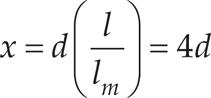
where l/l m =4 is adopted in the present study. In addition, x is the x-axis displacement, which is generated at the tip of the microgripper jaw by an applied voltage V.
The actuator with integrated capacitive position sensor enables the generation of the real-time gripper jaw position. As shown in ((1)), the gripper moves with a linear motion once a certain voltage applied. Usually, when the gripper touch the target object, an external force that is equal to the grasping force is applied to the gripper jaw. The equation can be expressed as (5):
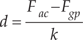
where F gp is the grasping force.
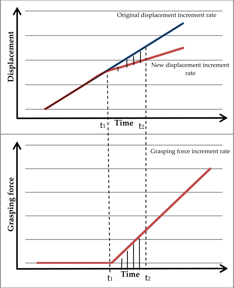
This external force will change the displacement increment rate. As shown in Figure 3, the grasping process can be classified into free phase and contact phase. In the former phase, the capacitive sensor acts as a position sensor, while in the latter phase, the capacitive sensor functions as a force sensor.
The relationship between displacement and grasping force
The blue line in the upper chart in Figure 3 denotes the original displacement without force applied. It describes the free phase increment rate without force applied. The free phase occurs before time t1 in which the external force is not applied. At a certain time (t1), the gripper jaw touches the object and the contact phase is induced. During this phase, since the external force is applied, the displacement incremental rate is changed. It follows that the sensor output signal is contributed to by both the driving displacement and the external force.
Therefore, the force signal needs to be extracted from the combined signal. Specifically, a factor can be determined below to give the relationship between the displacement and grasping force:

where ΔFgp and Δd are the change values of the grasping force and displacement, respectively, in the same time interval.
In practice, before the microgripper is used for the first time, it needs to be calibrated by the aforementioned method to find the factor (6). Then, the real-time position and force signal can be provided by the capacitive sensor in the free and contact phases, alternately.
In this section, both analytical method and FEA simulations are performed to validate the gripper's static and dynamic performance.
Table 1 shows the designed parameters of the microgripper. The gripper owns a compact size of 6.9 × 6.5 mm2. By employing a driving voltage of 120 V, the actuator force, stiffness, and output displacement are calculated by resorting to (1), (2), and (3), respectively.
Design parameters of the microgripper

Design parameters of the microgripper
FEA simulation is conducted using the calculated actuator force. The simulation results of displacement along the x-and y-axes are depicted in Figure 4 and Figure 5, respectively. Moreover, the performance of the microgripper is summarized in Table 2. It is observed that the discrepancy of the displacements of the gripper in the two axes as predicted by the analytical modelling and FEA simulations is less than 10%. Hence, the analytical models are confirmed by the conducted FEA. Because of their computational efficiency, the analytical models will be employed for an optimal design of the gripper dimension in the future.
Performance result of microgripper


The x-axis displacement result of FEA simulation
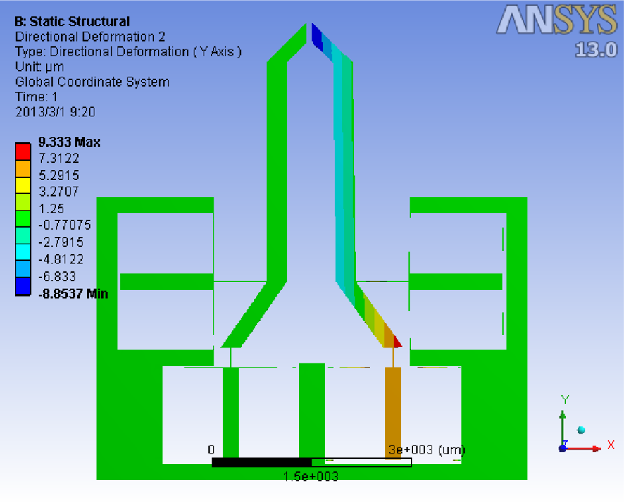
The y-axis displacement result of FEA simulation
In addition, both analytical model and FEA simulation reveal that the microgripper is capable of over 140 μm gripping range. With an initial gap of 50 μm between the two gripper jaws, the objects ranging between 50 and 190 μm can be grasped by adopting the designed microgripper.
From the dynamic modelling, some analytical calculations and FEA-based simulations are performed to validate natural frequency as follows. First, the stiffness of a leaf flexure can be calculated as:

where γ is the optimal value of the characteristic radius, the average value of γ=0.85 is used in the research, K t =2.669 is stiffness coefficient and I is the area moment of inertia:

where the parameters L f , t, and W f are shown in Table 1. The kinetic energy equation is shown as:

where q is displacement in working direction, for the x-axis, the mass m is expressed in (10) below.


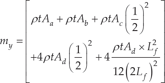
where the components a, b, c, and d are denoted in Figure 6. In addition, the potential energy along the x-axis is expressed as:
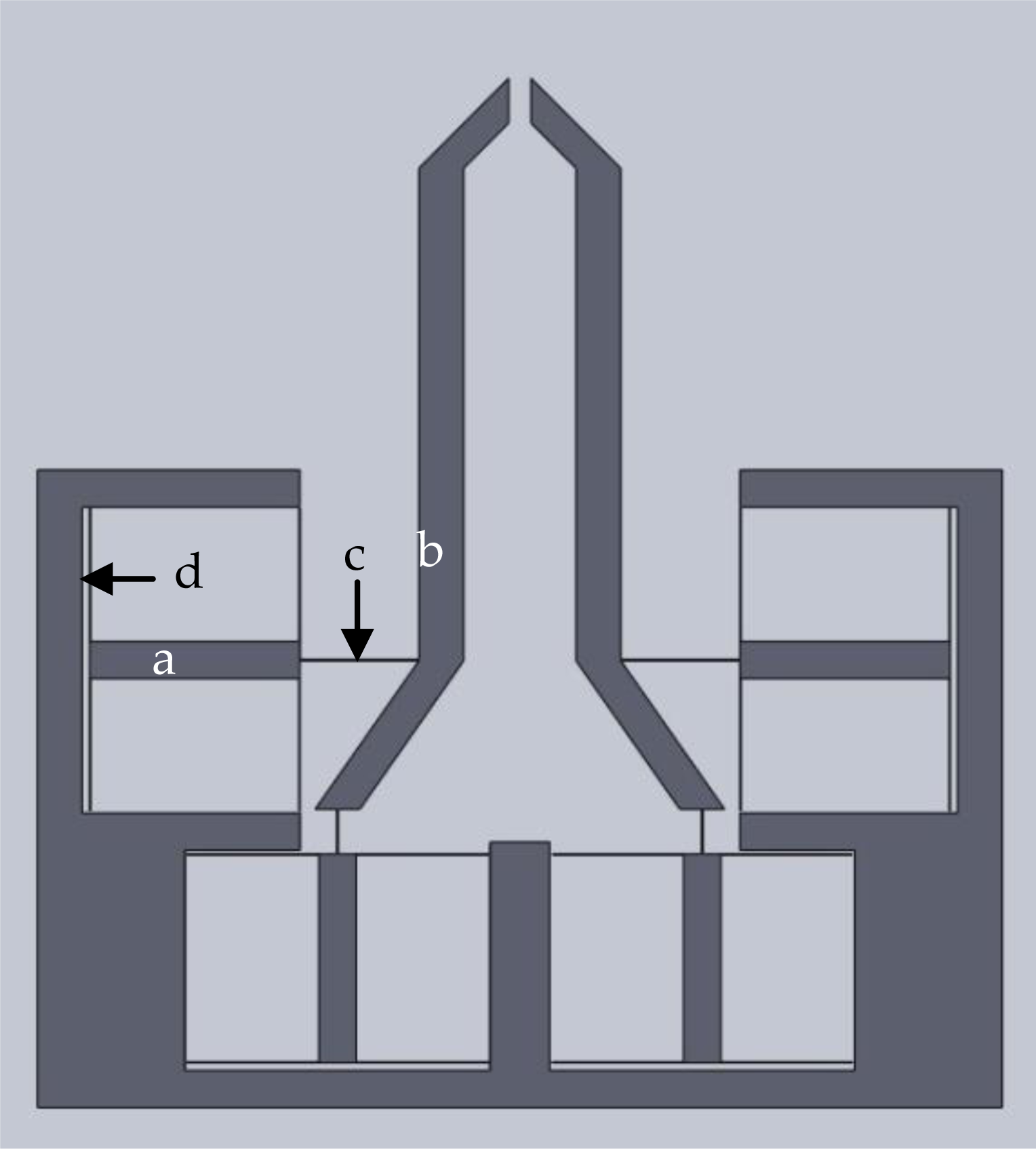
Illustration of various components of the microgripper

Substituting (9) and (11) into the Lagrange's equation:

where T, V, t, x represent the kinetic energy, the potential energy, time variable, and displacement in the working direction, respectively:

In addition, F is set to 0 to give the free motion dynamic model:
Modal analysis result of natural frequency along x-axis

Therefore, the natural frequency can be calculated as:

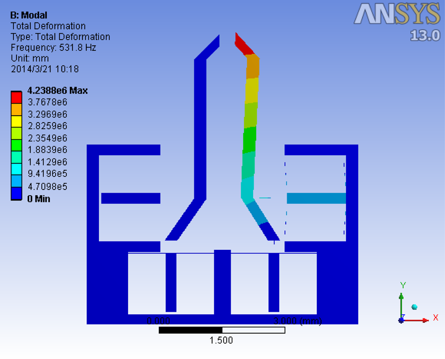
Modal analysis result of natural frequency along y-axis

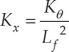
where the stiffness K x is shown as:

At the same time, the mass m and potential energy along y-axis can be calculated as shown in (17) and (18):

The stiffness K y can be expressed as:
Thus, the natural frequency along the y-axis can be calculated by substituting (17) and (19) into (15).
The performance of microgripper is shown in Table 3. Both analytical calculation and FEA result show that the natural frequencies along x-and y-axis are over 500 Hz and 1800 Hz, respectively.
Natural frequency result of microgripper

Moreover, the gripper also enables a precise positioning in the y-axis. As compared with conventional 1-DOF gripping, the 2-DOF positioning allows a more dexterous manipulation for practical applications. Fn the future work, a prototype of the designed microgripper will be fabricated and a simultaneous position/force control [22], [23] will be conducted through experimental investigations.
In this paper, the newly designed microgripper can provide over 70 μm x-axis and 18 μm y-axis displacements at the jaw tip with the force of 190 μN by applying a 120V driving voltage. Compared with existing design scheme, this concept endows the microgripper with the capabilities of achieving 2-DOF movement with large displacement and delivering real-time force sensing simultaneously. Two-side actuation and two-side sensing enables the microgripper a wider application in different field of environment. In this design, the length and width of the flexure connected with the electrostatic actuator are the key parameters of the system performance. To achieve the desired displacement (over 65 μm) and compact size (6.9×6.5 mm2), the range of these two parameters are under restriction.
As the width of flexure varies between 5 and 7 μm, a comparison study of the system performance including displacement and natural frequency is carried out. The length of flexure is fixed at 900 μm due to the limitation of the whole size.
As shown in Figure 9, both analytical calculation and FEA simulation are performed to test the system performance. The width of flexure is proportional to the displacement, whereas it is inversely proportional to the natural frequency. The objective of the test is to find out the maximum natural frequency when the displacement is over 65 μm. As can be seen from the results, although 6.5 μm and 7 μm width can provide larger natural frequency, the output displacements of the microgripper under these two parameters are less than 65 μm. Alternatively, when the width of flexure is 6 μm, the system exhibits the maximum natural frequency with over 70 μm displacement.
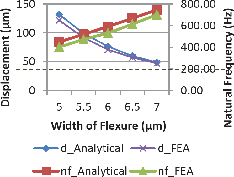
Comparison of system performance with different flexure parameters
In order to verify the capability of the microgripper structure design, a scaled-up model has been developed based on the design. Due to the relatively easier fabrication process and faster manufacturing time, the prototype is fabricated based on the scaled-up model. In this design, the PZT is selected to produce the main displacement instead of electrostatic actuator. Both analytical method and FEA are tested to verify the static and dynamic performances. The results have been compared with experimental results to show the detailed structure capability of the microgripper design.
Experiment setup
The prototype has been fabricated based on the scaled-up gripper design, the material is AL6061 and the actuator is PZT, which can generate the maximum stroke of 9 μm.
In this experiment, the PZT amplifier gain is adjusted as 10. The real-time output sensing is carried out by both an optimal microscope and a non-contact laser displacement sensor. The experiment setup is shown in Figure 10.

Experiment setup with actuator and sensor
Figure. 11 gives the experimental result for the displacement of the gripper. With the applied voltage signal, which has a magnitude of 11V, a displacement of 20.88 μm has been measured by the sensor. Figure. 12 shows the natural frequency result when the input signal is a swept sine wave from 10 Hz to 1000 Hz frequency with 0.1V amplitude. The system's response is measured in decibels, and the phase is measured in radians, versus frequency in Hertz. The measured natural frequency is 870 Hz.
Table 4 shows the analytical calculation, FEA simulation and experiment result of the scaled-up gripper. As can be seen from the table, there are 13.22% and 24.02% difference on displacement between the experimental results and analytical and FEA simulation results, respectively. The reason is that the reference point of the laser sensor is located at the arm of the gripper while the other two methods are tested at the gripper tip. After the calculation correction of the displacement, it is found that the displacement at the tip has a magnitude of 24.28 μm. At this moment, this result is confirmed by the conducted FEA simulation.

Experiment result of the gripper displacement

Experiment result of natural frequency evaluation
The performance result comparison

Besides, the tested natural frequency conducted by the experiment has more than 300 Hz difference compared to the FEA simulation and analytical calculation. In this case, the groove is designed smaller than the PZT actuator to fix it tightly, which causes a deformation of the gripper without voltage applied. This preloading effect enhances the stiffness of the whole gripper. Consequently, the natural frequency is increased after the assembly.
To conclude, the prototype based on the scale-up gripper design has been verified in the experiment. The results show that the microgripper structure design is feasible.
The design and analysis of an electrostatically actuated monolithic two-axis microgripper with integrated capacitive position/force sensors has been presented in this paper. For the purpose of grasping force sensing, the relationship between the grasping force increment and displacement ratio change is established. The performance of the microgripper has been verified with static and dynamic modelling by both analytical method and simulation with FEA. The results show that the displacement at the tip of each gripper jaw is over 70 μm and 18 μm along the x-and y-axes, respectively. The integrated capacitive sensor is designed to provide the real-time position and grasping force signals alternately. In addition, the natural frequency along both axes is examined. Testing results show that the parameters meet the desired requirement. A scaled-up prototype is fabricated and tested through the experimental study. The results show that the microgripper structure design is successful. The development of a control scheme is ongoing, and more experimental results will be presented in the future.
Footnotes
7.
The work was support by the Macao Science and Technology Development Fund under Grant No.: 070/2012/A3 and the Research Committee of the University of Macau under Grant Nos.: MYRG083(L1-Y2)-FST12-XQS and MYRG078 (Y1-L2)-FST13-XQS.