
Abstract
We have developed a robot system for closed diaphyseal fracture reduction. Because accuracy is essential for the treatment effects of the robot system and for the safety of both the patients and surgeons, we analysed accuracy in a systematic way. Both the structure of the robot and the operation procedure are described. Using the transfer model of errors in series and the error differential solving method for parallel mechanisms, an error model was established, and the main influencing factors of errors were considered. The Monte Carlo method was used to perform the simulation based on the error model. Experiments of image registration, of the mechanism and of the whole robot system were tested in different aspects to verify that the results of the simulation are correct. The system accuracy was compared with clinical standards to show that the robot system fulfilled the requirements for closed diaphyseal fracture reduction. The accuracy analysis method also provides an efficient path for other medical robots.
Introduction
In traditional fracture surgery, the fracture site is usually incised and reduced under direct version. However, this procedure is liable to destroy the blood circulation and enlarge the necrosis area on the fracture site. Some fracture treatments such as closed locked intramedullary nails have improved rapidly in recent years [1,2]. In addition to the advantages, there are also some disadvantages to this method. First, 40% of the bones of the patients have a rotation of more than 10° after an operation [3]. Second, continuous X-rays that are harmful for the surgeons and the patients are needed in a surgery [4]. Third, the surgeons have to provide a very large operating force, and the force sometimes even reaches 400 N [5]. Based on all of these factors, we considered using a robot to solve these problems. Robot-assisted orthopaedic surgery (RAOS) has been proposed and rapidly developed [6–9]. For example, the Acrobot® navigation system [9] has been successfully applied in total knee replacement surgery. From the aspect of robot-assisted fracture reduction, Bouazza-Marouf et al. [10] developed the first robot-assisted fracture reduction system in 1995. R. Westphal et al. [7] developed a surgical telemanipulator based on a large-scale industrial robot RX90 for femur shaft fracture reduction. S. Warisawa et al. [11] used the robot to assist surgery with tractive reduction based on the photoelectric tracking navigation, aiming at the femur and the femoral neck fracture. These researchers mostly adopted industrial robotics as fracture reduction devices, which cannot ensure accuracy or security. This kind of mechanical structure also brought inconvenience to the operation of surgeons. To overcome the above disadvantages, we have developed a robot system.
Accuracy is an important index for robot-assisted fracture reduction [12]. Because of the load concentration in standing and walking by the patients, a precise operation on fractured bone fragments is needed for strong osseointegration [13, 14]. If the angular deformity of the reduction is greater than 5° on any anatomical plane or the translational deformity is greater than 10 mm, the fracture is considered to be a malunion [15]. In terms of the robot, even small positioning errors could lead to dangerous and costly consequences. Considering the above factors, the accuracy of our robot system is designed to ensure that the angular deformity of the reduction is less than 3° on any anatomical, and the translational deformity is less than 5 mm. Taking the processing capacity and processing cost into consideration, we propose the accuracy of the robot itself. It should be higher than 2 mm in any direction of movement. Due to the complexity and specificity of the fracture reduction robot system, the accuracy of the system is usually associated with the imaging technique, registration, and mechanism. It is therefore a challenge to analyse a robot fracture reduction system systematically and comprehensively.
Some researchers have conducted numerous studies on the accuracy analysis of robots. For example, in 1978, K. J. Waldron et al. [16] proposed an integrated analysis method for operation robots. Y. Du et al. [17] analysed the error of a parallel robot by Edgeworth series and information entropy. In the field of RAOS, only limited clinical reports on accuracy have been published to date [18]. L. Hu et al. [19] analysed the error of navigation using the Taylor series expansion method. R. Ye et al. [20] researched the position accuracy of a closed diaphyseal fracture reduction system. These researchers clearly adopted different error analysis methods in researching their own robot systems because each robot system has its own distinctive structure and function.
Both the limit error method and the probability analysis methods are common ways to express errors. For the limit error method, the position is expressed by the boundary of the worst motion parameters. This method is too conservative. For the probability analysis method, the position is expressed by probability distributions. For our robot, the operation of fracture reduction is independent every time. Either the mechanism assemblage or the processing errors are random. In this paper, the probability analysis method has been selected.
The purpose of this paper is to analyse the accuracy of the robot to verify the reduction requirements for accuracy. The rest of this paper is organized as follows: section 2 introduces the system constitution and describes the operation procedure. In Section 3, the error source is analysed, and an error model is presented. In Section 4, the errors are verified by the simulation and experiments. Finally, the errors of each link are analysed and discussed, and future work is put forward.
System overview
The system structure
We have analysed the operations of the surgeons in fracture reduction surgeries and confirmed system configuration after obtaining constraint conditions. The robot system for closed diaphyseal fracture reduction is shown in Figure 1. This robot system is composed of a data processing and surgery planning system, a control system, a fixing unit, and a reduction unit.
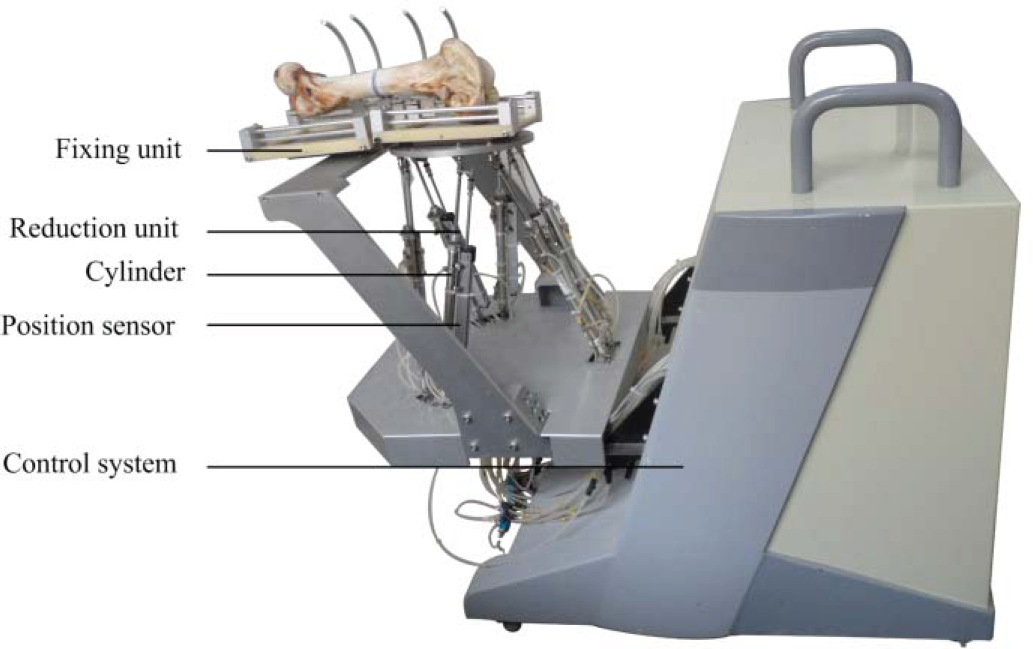
The robot system for closed diaphyseal fracture reduction
We adopted two types of software to run in our personal computer (Intel(R) Core(TM) 2 Duo, 3.00 GHz): Mimics (Mimics 10.01, Materialise Company, Leuven, Belgium) and the software that we designed. Mimics is used to reconstruct three-dimensional (3D) models based on computed tomography (CT) images of the femur. With our software, we computed target poses by the image registration, planned the robot's path, obtained the desired motion data of the robot and sent the data by establishing a connection with the control system.
The control system
The control system is used to receive the data from the host PC and to control the motion of the robot. It consists of a controller which is based on an embedded system, 6 stepper motor drivers and a 6-channel A / D signal collector. After the motion data of the robot is planned on the PC, it would be sent to the controller and the controller would convert it into a pulse signal to control the stepper motor through the driver. The A / D signal collector is used to acquire signals of position sensors (linear accuracy 0.06%, WXXY Co., Ltd, China) attached to the rods of the reduction unit. This signal will feed back to the controller as the actual value of the rod length. In the controller, the position close-loop control method based on PID algorithm was adopted.
The fixing unit
The fixing unit is used to fix the injured femur before the operation. There are two bottom plates, which are mutually connected by two connecting plates. Each bottom plate is also connected with brackets. Combining the clinical experience of surgeons, we implanted needles into the two ends of the fractured bones, and connected the needles to the bracket. In this way the two ends of the fractured femur would be fixed on the two bottom plates of the fixing unit. At the bottom of the fixing unit, a fast interface was installed, which could be connected to or removed from the reduction unit. The fixing unit and the patient should be together to take the preoperative CT scan. In order to get a better CT image, we chose a kind of plastic with low density, as the material of the bottom plates and the connecting plate. To ensure rigidity, we chose aluminium to make the bracket.
The reduction unit
Robots used for the reduction must have six degrees of freedom, and a large operating force and high precision for the reduction. To ensure the safety of the surgeons and patients, a robot does not need much working space. The ease of operation of the robot should also be considered. The Stewart mechanism with 6 degrees of freedom features a large load capacity, high precision, suitable working space and ability to meet the requirements, so the Stewart mechanism is adopted for the reduction. Because the Stewart mechanism is placed beneath the patient, its large size will not affect the surgery. The Stewart mechanism includes a moving platform, a static platform, and driving rods between the platforms. The main parameters of the Stewart mechanism are shown in Table 1. The platforms and the driving rods are connected with hook joints. We adopted six sets of cylinders (inner diameter 16 mm, elongation 200 mm) as the driving rods. These cylinders are connected to another group of cylinders by the hydraulic tubes. The movement of these two groups of cylinders is synchronously driven by the step motors.
Main parameters of the Stewart mechanism

Main parameters of the Stewart mechanism
In terms of this reduction unit, the influential factors of the mechanism's accuracy can be summarized as follows: the position errors of the hook joints that are connected to the moving platform and the static platform, the length errors of the driving rods in the movement of the reduction, and the deformation errors caused by rigidities of the moving platform and the static platform. The last kind of error can be resolved by enhancing the stiffness of the material, so we ignored it when analysing the errors of the reduction unit.
The operation procedure, shown in Figure 2, includes the preoperative operation, the data processing, the intraoperative operation and the postoperative operation.
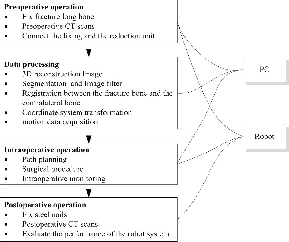
The operation procedure of the robot system
The ring support on the fixing unit can be adjusted flexibly for implanting steel nails into the fragments of the femur bone. The connecting plate was used to fix the fixing unit. The CT data of the fracture bone, of the fixing unit and of the contralateral bone could be acquired from a Spiral CT (LightSpeed VCT, GE) with a slice thickness of 1 mm and a pitch of 1 mm. The host PC was then connected to the control system based on the local area network (LAN) to establish the communication. The robot was adjusted to the set position. The fracture bone on the fixing unit was connected to the reduction unit.
The data processing
The CT data were reconstructed into 3D models in the STL format. The CT data included three parts: the proximal fragment, the distal fragment and the contralateral bone in Mimics. Image filtering is essential for better registration results. The 3D model was then processed by our software based on the visualization toolkit (VTK). Another fixing unit of the STL format with coordinate information was created by SolidWorks (SolidWorks 2010, Dassault Systemes S.A, France), and this unit was imported into the software. The iterative closest point (ICP) [21, 22] algorithm was adopted and is described by Eq. (1):

In this equation, pi stands for points in the target area and qi stands for those that must be registered in the area. The parameters R and S stand for the rotation matrix and the translation matrix, respectively. These matrices can be obtained by seeking the optimal solution of this equation, and they can be expressed by an R~(4×4) homogeneous coordinate matrix.
Due to the physical symmetry of the femur bone [23], we registered the proximal fragment and the distal fragment to the contralateral bone by the ICP algorithm mentioned above and acquired the pose transformation matrices Tp and Td, respectively (Figure 3). The corresponding pose transformation matrix of the distal fragment to the proximal fragment is T−1 p Td. Image processing is done in the CT image coordinate space {C}, while the robot is in the robot coordinate space {R}, so it is essential to change {R} to {C}. The mapping relationship of point set P in {R and {C} is described by Eq. (2):


Pose transformation of 3D model in the software
In this equation, Tm stands for the transformation matrix from {R} to {C}. The corresponding pose transformation matrix RT of the distal fragment to the proximal fragment in {R} can be described as

The corresponding position of the proximal fragment to the static platform is fixed. The position is the same as the position of the distal fragment relative to the moving platform. RT is the corresponding pose transformation matrix of the moving platform relative to the static platform in {R}.
To describe the motion of the reduction unit, we established the base coordinate {B} on the static platform, the moving coordinate {A} on the moving platform and the fracture end coordinate {G} on the femur bone (Figure 4).


Schematic diagram of the reduction unit
In Eq. (4),

In Eq. (5),

We define

The length variation Δ

We have analysed the features of different types of fractures. Our robot is suitable for certain types of fractures, but not all. The two aspects mentioned above have been elaborated upon in [24]. To avoid collisions of the fragment bones, we plan the path of the robot in a visual interface of the software by moving the positions of the 3D models. Then, the robot performs an automatic fracture reduction based on the planned path. In our software, we could arbitrarily change the distal pose of the fractured bone and acquire the relative transform matrix of the distal pose to the proximal pose by calculation. Consequently, we operated the distal end of the fractured bone through the interface on the PC and attained a few key poses as the waypoints of path planning. For common fractures, we usually stretch the distal end to leave enough room for its motion, then rotate and translate the distal end to shorten it to reduction. There is a real-time mapping relationship between the model and the real broken bone. If an emergency arises in the course of the operation, such as collisions of broken bones, the surgeons could see from our software and then issue a directive to stop the robot. In addition, if there were some faults in the control system and the movement of the robot could not be controlled, surgeons could cut off the power supply by the emergency brake switch. These measures provide a powerful safeguard for the patients during the operation
The postoperative operation
The steels of the fractured bones need to be fixed by the rods when the fracture reduction operation is finished. Furthermore, a postoperative scan is necessary for acquiring the data of the fracture bones, which are useful in calculating the reduction accuracy.
The error model
The influential factors of robot system errors include the following aspects. First, fracture reduction is based on the preoperative CT data. The data processing algorithm may lead to errors. Second, the nominal value of the mechanism parameters is different from the actual value due to the manufacture, fabrication and rigidity of the material. Third, the outcome accuracy of the control system is influenced by the control algorithm and the positioning sensor.
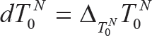
We analysed the main errors of the robot system from the list above and classified them into two types: image registration errors and mechanism errors. The image registration errors were analysed by utilizing the transfer model of errors in series [25, 26]. The homogeneous coordinate transformation TN0 is described by

where Ti represents the ith homogeneous coordinate transformation and i = 1,2,…,N. If the error of Ti is minute,

where Δ Ti is the corresponding perturbation matrix to coordinate {i}. The higher-order term is ignored. The expression is described by

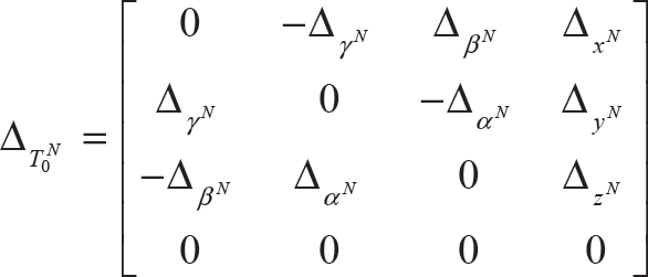
where Δ xi , Δ yi , Δ zi and Δαβ, Δβi, Δγi represent the generalized positions and angular errors of the nominal coordinate axes xi, yi and zi, respectively, dTN0 represents the perturbation matrix of the terminal pose that can be described by
In Eq. (12), Δ T N 0 represents the terminal perturbation matrix for the base coordinate {0}:
Let
Eq. (9) shows that

We substituted Eqs. (10) and (12) into Eq. (14) and ignored the higher-order term:

In the Eq.,
Let

We solve Eq. (16) and substitute Eq.(3) into it:

In Eq. (17),
Next, using an error differential solving method, we analysed the errors of the parallel mechanism. Then, we differentiated Eq. (7) and finished it. The error vector δe of the moving platform is obtained:

In Eq. (18),

δ

JC is the direction vector along the driving rod:

From Eqs. (17) and (18), the error δ
B

The error

In Eq. (23),
To research conveniently, we expressed the accuracy of the fracture reduction by the axial displacement

We have tested the accuracy of the robot system in several ways. First, the whole robot system was simulated based on the error model. Second, tests were performed to verify the errors of the image registration and the mechanism. Finally, the accuracy of the robot system was tested with a bovine bone model, and the results were compared.
The error simulation of the robot system
In the error model, the input errors mainly caused by manufacture and fabrication obey the normal distribution. As a probabilistic algorithm, the Monte Carlo method is a suitable method for accuracy analysis of the fracture reduction robot system; it was thus adopted [27]. The random data err ~N(0, σ) with sample size N, which obeys the normal distribution, were generated in Matlab. The value of σ is determined by the principle of ‘3σ’ and the range of errors. According to the operational experience and the processing and manufacturing accuracy of the robot, the positioning error ranges and the rotation error ranges of the image registration are ±0.2 mm and ±0.5°, respectively. Both the error ranges of the positions of the hook joint centres and the positions of the lengths of the driving rods are ±0.5mm. The data were substituted into the equations of the error model, and the data were simulated in Matlab. The sample size is 1000. The results are shown in Figure 5.

Results of the robot system simulation
The simulation results show that the mean values of the positioning errors are less than 2.5 mm, that the mean values of the rotation errors are less than 0.5°,
Accuracy tests of the image registration
The image registration principle of the femur bones is the same as that of the coordinate transformation. We only tested the registration accuracy of the femur bones. The test was repeated ten times with bovine bones. The bovine bone has a high similarity to the human bone in structure and shape. Although the sizes of human and bovine bones are not exactly the same, the final verification is not affected. The process is shown in Figure 6.

(1). (a): the intact bovine bone before fracture; (2) (
The main difficulty in designing the experiments to validate our approach is that there is no ‘golden standard’ for determining the correct absolute value. Instead, we designed the following method: first, we obtained a 3D model of the bovine bone (a) (Figure 6. (1)); second, we broke the bovine bone (
The ICP algorithm is utilized for the registration of (
Based on the forward kinematic results of the parallel mechanism [28], the poses of the moving platform in {A} under these two conditions are calculated.
The pose error of the moving platform can be calculated from the results of step 3 of the method.
Errors caused by the image registration
From the results, errors caused by image registration can be observed clearly. The mean value of
The accuracy of the mechanism is another important factor that influences the accuracy of the robot system. The accuracy of the Stewart mechanism was tested by the Micron Tracker (Claron Technology Inc. Canada), a vision sensor for measuring the positions of objects in 3D spaces. Its main parameters are shown in Table 2
Main parameters of the tracker

Main parameters of the tracker
As Figure 8 shows, the tracker was placed near the robot system to elucidate the visual field. Their relative positions needed to be fixed. The marked paper was pasted to the centre of the moving platform to be distinguished by the tracker. The tracker was connected to the PC by the data lines. The coordinates of the marker can be obtained by the software running in the PC.
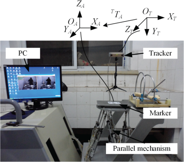
The accuracy test platform for the mechanism
The Stewart mechanism was adjusted to the initial position. In this position, we take the coordinate {A} as the reference coordinate system. The centre point TP of the moving platform in {T} and the coordinate transformation matrix
T

From Eq. (26), the error of the robot movement can be described by:

Where TP0 and TP1 represents the theoretical coordinates before and after the robot movement;

Errors of the mechanism
As the input errors of the mechanism obey the normal distribution, the population of the error data is also normal. From the results, the mean errors in x and y directions are similar. They are smaller than 1.2 mm. The mean error in z direction is smaller than x and y directions.
We used five pairs of bovine bones to test the accuracy of the whole robot system, because bovine bones are close in length to the bones of patients. The operation procedure was performed as described in section 2.2. Some important steps are shown in Figure 10, and the results are shown in Figure 11.

(a) The fractured bone in the fixing unit and the contralateral bone before CT scans; (b) the fixing unit connected to the reduction unit for the operation; (c) the registration between the fracture bone and the contralateral bone in the software; (d) bone status in the robot after the reduction

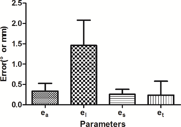
Errors of the accuracy tests of the robot system
From the average values and the standard deviations shown in Figure 11, the average displacement deviations are observed clearly to be less than 2.5 mm, which is close to the simulation results, and el is larger than ea. The average angular deviations are less than 2°, a little larger than the simulation results.
This paper concentrates on the accuracy of the fracture reduction system, and verifies this accuracy by test experiments. The errors have many causes. We analysed the main reasons based on the mathematical model: the image registration errors, and mechanism errors.
The image registration errors were tested in experiments based on a pair of bovine bones. Due to individual differences among bones and their different positions in the robot, the acquired data for each operation are different, but the final errors are nearly the same. The mean value of
In our experiment, the bovine bone was cut halfway orthogonally along its length because it would be easier for us to observe the errors after this reduction. The clinical situation is much more complex: the bone is usually splintered into many pieces. Plastic deformation has occurred. As a result, based on the biological osteosynthesis (BO) technique, we attached great importance to the blood circulation of the local soft tissue and took the contralateral bone as the reference standard. What we observed carefully were the right poses of the fracture ends rather than its fragments. After the poses of the fracture ends are fixed, it would be easier to adjust the bone fragments manually.
For clinical purposes, a safe and aseptic environment is very important to the patient, and achievement of the robot's high accuracy reduction is an important measure to ensure safety. In addition, we made a preoperative path, planning to prevent collisions of the bones and monitor the operation of the robot during the surgery. Since perforated holes on both sides of the fracture instead of the incision are needed, the surgery performed by our robot is minimally invasive and could ensure sterility. The needles and fixing mechanism can be sterilized before the surgery, and the body of the robot can be covered with plastic sheeting during the reduction.
In this study, we described the structure and operative procedures of the fracture reduction system. The error model was established with the application of the transfer error models in series and the error differential solving methods for the parallel mechanism. The simulation was performed based on the Monte Carlo method. Accuracy was tested by experiments, including the image registration, the mechanism, and the robot system. These experiments verify the validity of the simulation. The accuracy fulfils the requirements of the fracture reduction. The error analysis method also provides an efficient outline for other medical robots. In the future, we will work to modify the mechanical configuration and will use other methods to further improve accuracy based on this study. For example, the visual servo control can be adopted to improve the robot's accuracy. The accuracy experiments will be tested with bones covered with muscles to verify the influence of muscle strength.
Acknowledgments
This research was supported by the National Key Technology R&D Program (2012BAI14B02) and National High-tech R&D Program (863 Program) (No.2012AA041405 and 2012AA041604).