
Abstract
The 3D assembly of cellular structures is important for the fabrication of biological substitutes in tissue engineering. In particular, a micro-channel with a 200 μm diameter is of interest because of its promising ability to construct the vascular network for oxygen and nutrition delivery in thick biological substitutes in the future. In this paper, a novel rail-guided micro-robot-team system is proposed for the micro-assembly of a cellular structure. The cellular two-dimensional (2D) component was fabricated by ultraviolet (UV) illumination of a cross-linkable hydrogel. The modular rail-guided micro-robotic system was set up with multi-micromanipulators as the modules and controlled with hybrid motors to achieve an operation resolution of 30 nm. To realize the bottom-up fabrication of the cellular micro-channel, different micro-assembly strategies with multi-manipulators were developed. The micro-assembly success rate and the efficiency of the different strategies were evaluated based on the assembly of micro-donuts. Through the novel, designed, concentric movement of the multi-manipulators along the rail, arbitrary change of the approaching angle and the coordination posture was achieved to improve the micro-assembly's flexibility. The operation range for every micromanipulator in different coordinated manipulation modes was analysed to avoid the breakdown of the assembled 3D structure. The image processing for the target location and end-effector identification was conducted to improve assembly efficiency in the micro-robot-team system. Finally, the assembly of the cellular vascular-like micro-channel was achieved with coordinated manipulation in the rail-guided micro-robot-team system.
1. Introduction
As one of the innovative biomedical technologies, tissue engineering has echoed wide concerns in pursuing the goal of harvesting human tissues in in vitro cultivation. The clinical application of engineered tissues has been realized in several tissues, such as skin, the cornea and cartilage [1]. However, there remain challenges on the way to engineering complex organs, like the heart, liver and kidney. One of the challenges to fabricating a complex biological substitute is the difficulty in achieving thick, three-dimensional heterogeneous composite tissues with a vascular network [2–3]. As the extra-matrix of cells in complex tissues, the vascular network plays a key role in providing access for oxygen- and nutrition-delivery [4]. Although oxygen-delivery based on the phenomenon of diffusion can happen within 100-200 μm, the inability to generate vascular-like structures thinner than 200 μm still hinders the realization of complex tissues with biological significance [5]. To solve the issue of organ loss and radical failure, a new fabrication method aiming at vascular-rich structures needs to be addressed.
The existing fabrication methods for vascular-rich structures are top-down scaffolds and bottom-up microfluidic-based systems [6]. Scaffolds serving as an artificial extracellular matrix provide optimal cellular environments for penetration, ingrowth and vascularization [7–8]. Through biodegradation and the growth of cells at the ratio, a vascular network can be achieved [9]. However, control of biodegradation is limited, which results in the difficulties in fabricating a 3D tissue with micro-scaled structures. The emergence of 3D printing techniques with sacrificial moulding improves the properties of the scaffold, and a controllable scaffold network was achieved for the perfusion of an engineered tissue [10]. From a fluidic point of view, microfluidic systems have emerged as promising tools in building the pathological models of the vasculature. Through the assembly of three-dimensional (3D) cell structures with the precise manipulation provided by optical tweezers, DEP and fluidic forces, a vascular-like structure can be realized [11–15]. Our team has developed dielectrophoretic microfluidic devices for cell patterning and assembly [16]. However, the strict operation requirements and the closed environment of the system hinder flexibility during assembly of the 3D structure. It is difficult to fully remodel native vessels by a fabricated microvasculature incorporating micro-channels with rectangular cross-sections [17].
Recently, micro-robotic techniques aiming at the observation, measurement and immobilization of micro-/nano-scale objects have been developed [18–20]. A micro-assembly technique with a micro-robotic system has been applied in manufacturing and biomedical research [21]. In particular, mechanical micro-gel assembly techniques with optical or magnetic micro-robotic systems provide novel methods for bottom-up assembly with higher controllability [22–23]. As one method of bottom-up assembly in generating complex biological tissues, through direct contact between the mechanical end-effector and the microstructure without the restriction of the operational environment interfering (electrically or optically), micro-robotics can provide more stable and flexible manipulation with a greater force [21]. For most micro-robotic systems to be able to assemble a cellular 3D structure, the main issue is how to achieve precise control and direct contact of the assembly units during manipulation. Due to the uncertainties in the micro-world, with a confined working space under the microscope, unpredictable dynamic effects strongly influence manipulation [22–23]. For example, the increasing influence of adhesion forces hinders the precise release of the microstructure [24]. Many micro-robots can only approach and manipulate the microstructure in one direction. The tip of the end-effector is difficult to rotate around a specimen, with different posture required for complex, coordinated manipulation [25]. In our previous research, the assembly of a 3D structure was realized with dual dextrous sticks in cooperation. However, the arbitrary changing of tip posture in optimizing coordination during assembly was not performed [26]. To realize the bottom-up assembly of heterogeneous components to a 3D structure, sophisticated, coordinated manipulation as implemented by multi-micro-robots still needs to be addressed [27].
In this paper, we proposed a novel bottom-up assembly method of cellular 3D hydrogel structures based on rail-guided, micro-robotic, coordinated manipulation. As shown in Figure 1, in order to realize an arbitrary change of end-effector posture during micromanipulation, we amended our previous dextrous-stick coordinated manipulation system (DeSCom) to become a rail-guided DeSCom system. Coordinated manipulation among the multi-manipulators was performed with concentric movement along the rail to improve the flexibility of manipulation. The 2D microstructure encapsulating the cells was fabricated as the assembly components. To define the different functions of the micromanipulators, micro-assembly strategies were developed and evaluated. To improve the micro-assembly's efficiency, an operational range for every manipulator for different coordinated manipulation tasks was assigned and then improved with the vision feedback system. Finally, a cellular vascular-like micro-channel with a length of around 1.5 mm was achieved. In the future, the team's micro-robot micro-assembly will be utilized to fabricate other hole-based micro-channels with different rod-shaped outlines and different cells for tissue engineering.

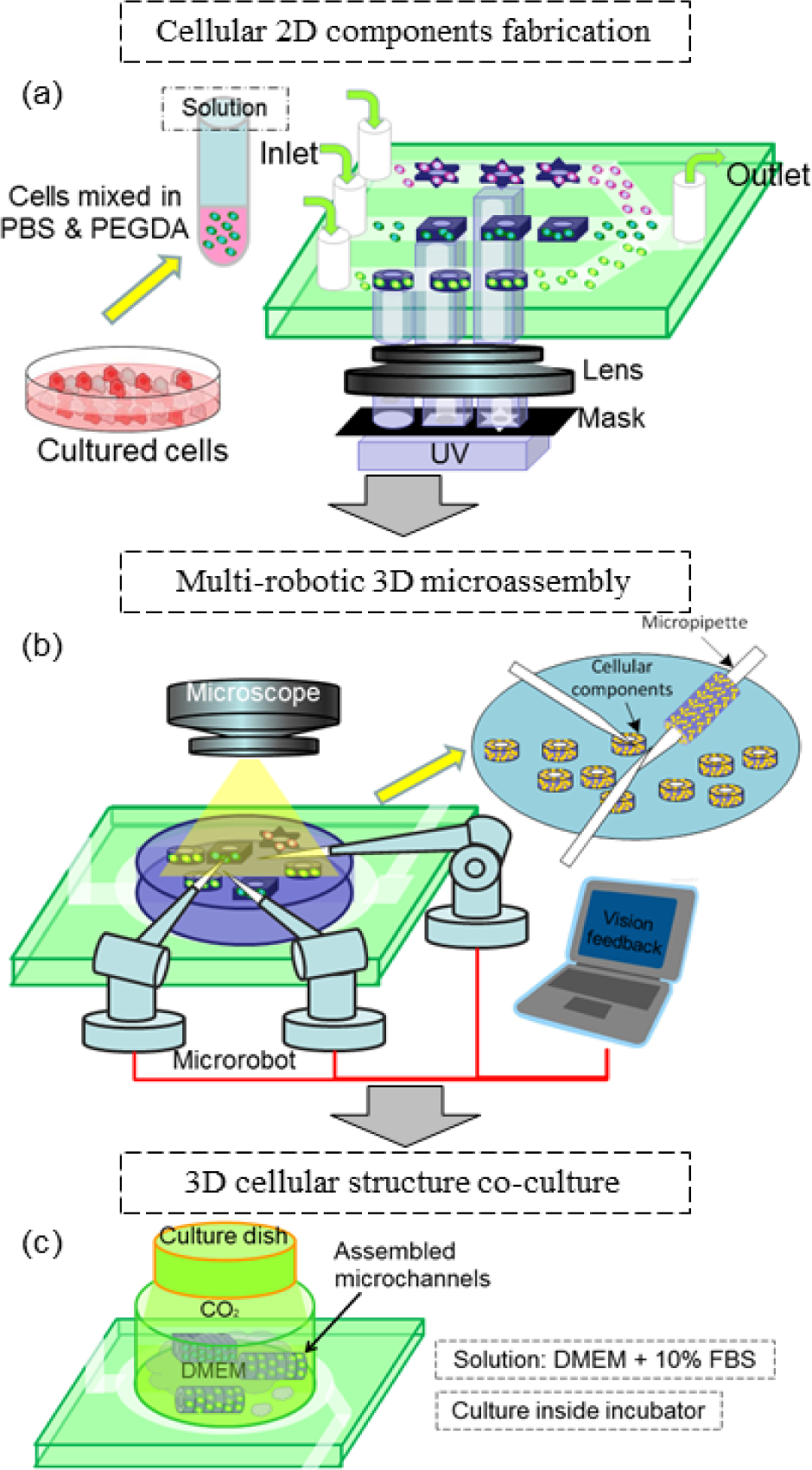
A schematic drawing of a 3D cellular structure assembly with a rail-guided micro-robot-team system
2. Cellular 3D microstructure assembly system
2.1. Overall micro-assembly procedure
The overall procedure for the micro-assembly of the cellular micro-channel based on coordinated micro-robotic manipulation is shown in Figure 2. Instead of building the micro-channel as a whole, we assembled the 2D cell-embedded micro-components from the bottom-up. The procedure included the on-chip fabrication of 2D cell-embedded components, the assembly of 2D components with micro-robot team-coordinated manipulation and, finally, the co-culture of an assembled cellular micro-channel.
A schematic drawing of the overall procedures for the multi-robotic assembly of the cellular micro-channels
As shown in Figure 2(a), we encapsulated the cells inside the biocompatible hydrogel as 2D components, which aimed to form the expected structure for bottom-up assembly by the micro-robot team and protect the cells from direct contact with the glass pipette. The cells were mixed with hydrogel and injected into the microfluidic channel for the on-chip 2D components' fabrication. Through the cross-linking of the sensitometric hydrogel in the channel, we fabricated arbitrarily shaped 2D components with a predefined profile. After the on-chip fabrication, the 2D components were collected for micro-assembly under the optical microscope. As shown in Figure 2(b), through the assembly of the different 2D components layer by layer, 3D structures with the expected morphology can be achieved. The size of the assembled structure can be easily regulated by controlling the total number of the 2D hydrogel components in the assembled array. After the assembly of enough 2D components, secondary UV exposure was conducted to solidify the assembled components as a complete 3D structure which was finally released for co-culture. The rail-guided micro-robot-team system was implemented here to realize different coordinated manipulations for complex tasks during assembly. The micro-robots were restricted to the rail and the end-effectors could interfere with the tasks using different postures via concentric movement along the rail. In considering assembly efficiency, the image acquired from the optical microscope was utilized as vision feedback. With the image processing and the task recognition, cooperation between the end-effectors based on image feedback was established. As shown in Figure 2(c), after micro-assembly by the multi-robotic system, the assembled 3D cellular micro-channels were removed to the culture dish and then cultured in the incubator for harvesting.
2.2. Micro-robot-team manipulation system setup
As shown in Figure 3, we integrated the modular rail-guided micro-robotic system under an inverted optical microscope (OM). The micromanipulator in the system was modularized, which means that different numbers of micromanipulators could interfere with the micro-assembly according to the complexity of the tasks. The entire micro-robotic system was set up with three subsystems incorporating rough control, fine control and vision feedback. The modular micromanipulators were restricted to the rail and driven by a stepping motor (model 398867, Maxon Motor Inc.) for rough control. Through the concentric movements derived from the stepping motor, the micromanipulators could move along the rail and the tip of the end-effector could rotate around the specimen without moving outside the visual field of the microscope, which is important for cooperation utilizing arbitrary changes of posture among multi-robots. For every manipulator on the rail, a piezo motor (model 8353, New Focus Inc.) was utilized to realize fine control. By driving three prismatic joints along the X-Y-Z directions, the micromanipulation resolution was determined to be around 30 nm. The solid glass rod (G-1000, NARISHIGE Inc.) was chosen for the fabrication of the glass pipette, in consideration of its intensity, to avoid damage during manipulation. The glass pipette was pulled as the end-effector (P-2000, SUTTER Inc.) and the dimension of the pipette tip was around 10 μm. The vision feedback sub-system was developed to improve the assembly's efficiency. Through the processing of images captured from the OM, the target's location and task optimization were achieved. The distance information was utilized for the automatic approach of the micromanipulator to the target during micro-assembly. For sophisticated assembly tasks in the future, more modular manipulators can be incorporated into the rail-guided micro-robotic system to improve manipulation flexibility.

Setup of the micro-robot-team system under an optical microscope
2.3. On-chip fabrication of 2D cellular components
As shown in Figure 4, we utilize the microfluidic channel to fabricate the 2D components. The fabrication method is based on the sensitometric characteristic of the cross-linkable hydrogel, which can solidify with exposure to UV light [28]. The microchip was set up under the OM (IX-71, Olympus). Through the adjustment of the X-Y stage and the height of the objective lens in the Z-axis, the exposure position in the microfluidic channel was controlled. Since the shape of the polymerized hydrogel was determined by the exposure profile of the UV light, we covered the UV light source with PET (polyethylene terephthalate) masks. To achieve predefined physiological architectures, the profiles of the masks can be arbitrarily changed to different 2D component shapes. UV was emitted by a mercury lamp (USH-103tems) with a controllable shutter (BSH-RIX, Sigmakoki) and focusing in the microfluidic channel through an objectives lens (UPLFLN 100XOI2, 60X and 40X, Olympus). Finally, after the exposure of the cell-mixed hydrogel, the expected 2D structure was polymerized and the surrounding cells were encapsulated into the structure.

On-chip fabrication of the cellular 2D components
The NIH/3T3 cell, as one type of fibroblast to form the outer layer of the vessel, was chosen to demonstrate the fabrication of the 2D components. The cells were mixed with poly(ethylene glycol) diacrylate (PEGDA, molecular weight 700, Sigma Aldrich), which is biocompatible and exhibits mechanical properties similar to those of soft tissues after polymerization. Prior to the experiment, the cells were cultured inside Dulbecco's modified eagle's medium (DMEM, Sigma Aldrich) with 10% foetal bovine serum (FBS, Sigma Aldrich) for 72 hours and mixed inside phosphate-buffered saline (PBS, Wako) to form a PBS cell solution of 107/mL cell concentration. The experimental solution was formed with a 272 μL PBS cell solution, 120 μL PEGDA and 8 μL photoinitiator (Irgacure 2959, Ciba). As shown in Fig. 5, after the exposure of the cell-mixed PEGDA to UV light, the 2D donuts were fabricated and the NIH/3T3 cells embedded in the donuts were stained and observed under fluorescent light. As shown in Figure 5, the 2D donut was fabricated and the NIH/3T3 cells were encapsulated inside.
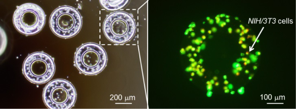
Fabricated 2D components embedding cells inside
3. Coordinated manipulation strategies for micro-assembly
To assemble the micro-channel from the bottom-up, we developed several micro-assembly strategies with different forms of cooperation between the micromanipulators. In the different strategies, we assigned different functions to the micromanipulators and the final assembly places of the micro-channels were different. The micro-donuts as 2D components were utilized to demonstrate the assembly of the micro-channel in all the strategies.
3.1. Transition micro-assembly with dual-manipulators
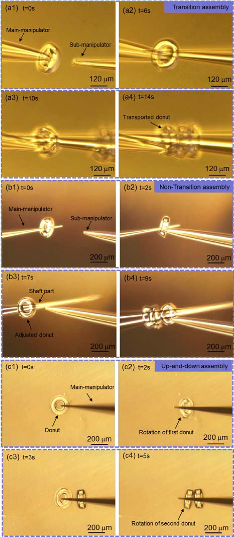
The manipulation procedure of transition micro-assembly is shown in Figure 6(a). We defined the dual-manipulators as a main-manipulator and a sub-manipulator. The main-manipulator first picked up the donut in the dish and the donut itself remained near the tip of the main-manipulator. To make room for more donuts, the main-manipulator approached the sub-manipulator and transported the picked donut to the shaft part of the sub-manipulator through the inner hole of the donut. The main-manipulator repeated the previous procedure to transport more donuts and, finally, the assembled micro-channel remained on the sub-manipulator. Since transportation between the two manipulators needed accurate alignment in the Z-axis to poke the tips into the inner hole of the donut, it took a long time to assemble one layer on the sub-manipulator, which is not efficient.

Manipulation procedures of three assembly strategies
3.2. Non-transition micro-assembly with dual-manipulators
To eliminate the transportation of the picked donut, we developed a non-transition micro-assembly strategy, as shown in Figure 6(b). In this strategy, the function of the main-manipulator was to immobilize the donuts while the sub-manipulator adjusted the posture of the picked donut. After the main-manipulator picked up the donut, the sub-manipulator approached the main-manipulator and pushed the picked donut from the tip to the shaft of the main-manipulator, which created new space to assemble more donuts. Finally, the assembled micro-channel was immobilized on the main-manipulator. Without transportation during assembly, efficiency was improved. However, in considering the fabrication of a micro-channel with multiple layers in a short time, it is still not efficient enough.
3.3. Up-down micro-assembly with a single manipulator
Based on the non-transitive micro-assembly strategy, we developed a novel, efficient strategy which only requires a simple up-down movement of the main-manipulator in the Z-axis. The basic method of micro-assembly is shown in Figure 6(c). The main-manipulator moved downwards to contact the donut. During the pressing of the main-manipulator against the donut at the contact point, the rotation of the donut derived from the kinetic torque occurred and the donut lay on the main-manipulator. The further approach of the main-manipulator caused the deformation of the tip and shortened the distance between the ground and the shaft. To protect the glass pipette from damage during deformation, the displacement of the tip was recorded when the donut started to rotate and compared with the predefined maximum acceptable displacement. As a result, the picked donut moved to the shaft of the main-manipulator without the help of the sub-manipulator. The main-manipulator moved upwards and this was repeated to rotate another donut. Figure 7 shows the mechanical analysis whereby the rotation of the donut happened. The relevant equations to determine the torque are expressed as:

Mechanical analysis of the donut during rotation


where
3.4. Experimental evaluation of the micro-assembly strategies
To evaluate the micro-assembly's efficiency, we carried out the micro-assembly of donuts based on a micro-robot-team coordinated manipulation with the mentioned strategies. Since the dimension of the micro-robotic tip size and the donut-shape influence the assembly's precision, we chose the same dimension before the evaluation of the strategies. We found that the assembly success-rate in relation to assembly precision was proportional to the dimension of the tip size in the axial direction and inversely proportional to the tip size in the radial direction. We chose the same shape for the donut with a 200 μm diameter and 70 μm thickness. We also found that, only if we controlled the dimension of the tip size to be less than 40 μm, could we protect the success rate from the influence of the fabrication error of the glass pipette tip. However, the tip size of the glass pipette that we used in the experiment was controlled between 10 μm to 25 μm with the same fabrication method, so the repeatability of the assembly's precision was ensured.
As shown in Figure 8(a), the donut with an outer diameter of around 200 μm was fabricated for the assembly. The main-manipulator first picked the donut and transported it to the sub-manipulator. It took around 15 s to assemble one donut layer with the transitive strategy. As shown in Figure 8(b), the main-manipulator first immobilized the donut near the tip. The sub-manipulator approached and pushed the donut to the shaft through the alignment under the OM. It took around 10 s to assemble a layer with the non-transitive strategy. As shown in Figure 8(c), we conducted the up-down micro-assembly to rotate the donuts one by one. Through the simple movement along the Z-axis, it only took about 2 s to assemble one layer.
Micro-assembly of donuts with different strategies
The micro-assembly of the donut is affected by the surroundings as well as the manipulation accuracy, which means that the assembly may fail to pick up or transport a donut. To evaluate the assembly success-rate, we repeated the micro-assembly of the donut with different strategies. For every strategy, the assembly experiment was carried out five times and every experiment was repeated 20 times to assemble a donut layer. As shown in Figure 9, the transitive micro-assembly has the lowest success rate, at 81%. This is because the transportation of the donut needs high alignment accuracy, which risks pulling down the assembled donuts from the shaft. Finally, to evaluate the assembly efficiency of the micro-channel with different strategies, we assembled a micro-channel with five donut layers. As shown in Figure 10, the assembly of a five-layered micro-channel was repeated five times for every strategy. As a result, the up-down micro-assembly has the highest efficiency, only taking around 13 s to assemble the micro-channel.

Micro-assembly success rate with different strategies

Micro-assembly time of a micro-channel with five layers
The up-down micro-assembly strategy exhibits the highest efficiency in building the cellular micro-channel from the bottom-up. However, to fabricate the micro-channel, more coordinated manipulation – including position adjustment and the release of the micro-channel from the shaft – needs to be considered. These manipulations need the complex cooperation in the micro-robot-team system, as they are impossible to carry out with the single-manipulator. To succeed in fabricating the cellular micro-channel, we chose the up-down strategy for the assembly, and we discuss the multi-manipulators' cooperation in completing the other stages of micro-channel fabrication in the next section.
4. Improved assembly of the micro-channel with multi-micromanipulator coordination
4.1. Coordinated manipulation with multi-manipulators
The fabrication of the cellular micro-channel is a complex procedure. During the up-down micro-assembly of the 3D structure, the further optimization of the assembled donuts still needs to be performed, including the adjustment of the assembled donuts and the release of the donuts from the manipulator for the co-culture. To realize these complex coordinated manipulations, we developed several coordination modes based on the rail-guided system in which the micromanipulators can frequently rotate with concentric movements and the tip of the manipulator can approach the micro-channel with the expected posture. The main-manipulator and sub-manipulators play different roles during coordination. The main-manipulator – as the main part – was involved throughout the whole period in picking up and handling the 3D structure. The sub-manipulators interfered so as to assist the main-manipulator and were only involved when the relevant strategy was triggered.
As shown in Figure 11(a), through the up-down micro-assembly, the donuts were picked up and immobilized on the main-manipulator. To eliminate the gap between the immobilized donuts during micro-assembly, the dual sub-manipulators approached the main-manipulator to adjust the position of the relevant donut, as shown in Figure 11(b). Through several rounds of up-down micro-assembly, the picked donuts all gathered near the tip of the main-manipulator. To make place for further assembly, the assembled donuts need to be compacted to the shaft. As shown in Figure 11(c), the dual sub-manipulators pushed the donuts upwards and both sides of the main-manipulator together to keep the force balanced and avoid the breakdown of the micro-channel. After picking up the desired number of donuts, secondary UV exposure was conducted to cross-link the surface of every layer with the picked donuts finally connected as a whole micro-channel. As shown in Figure 11(d), after secondary UV exposure the dual sub-manipulators cooperated to release the micro-channel from the shaft of the main-manipulator and move it to the culture medium for co-culture. The micro-robotic system – as a centralized system – was controlled by a central computer with vision feedback. The image processing information was utilized for the choosing of different strategies in different periods during assembly. As shown in Figure 12, the system set different criteria to trigger different manipulation strategies based on the image processing information. The first criterion was the distance between the glass pipette tip and the last-picked donuts, which determined whether it was acceptable to pick-up another donut. The second criterion was the actual number of the picked donuts, which was compared with the expected numbers. Both sets of information were acquired from the image processing and utilized to trigger different manipulators to achieve the task.

Micro-robot-team coordinated manipulation modes

Flow chart of the task planning during 3D assembly
4.2. Assignment of operation range in different coordination situations
In the developed coordination modes, the dual sub-manipulators frequently approached the main-manipulator in different directions. Such cooperation needs to be restricted to avoid breaking the assembled micro-channel. As shown in Figure 11, in consideration of manipulation efficiency and safety, we defined the operation angle θ between the main-manipulator and every sub-manipulator. While in adjustment mode and to eliminate the gap between the donuts, the relevant donut is always the last one near the tip. As shown in Table 1, to avoid collision with adjacent donuts higher up, the operation angle
Operation angle assignment for the coordination modes

4.3. Image processing for the multi-manipulators' coordination
After the evaluation and optimization of the coordinated manipulation, we developed a vision feedback system to realize coordinated task-planning. The function of the vision feedback has three aspects. The first one is to locate the donut and the tip of the glass pipette for automatic approaches and up-down movements. The second one is to detect the position and the orientation of all the manipulators and send back the position information for the coordinated control. The third one is to detect the state of the main-manipulator with the picked donuts, which was utilized to trigger different coordination strategies.
The image captured from the OM was utilized as the original image for the vision feedback system. As shown in Figure 13(a), during image processing grey-processing and binarization-processing were utilized to reduce noise. Based on the template-matching technique, the tip of the micromanipulator was taken as the template to identify the micromanipulator during micro-assembly. Figure 13(c) shows the template-matching result by which all the tips of the pipette were located. Since the shape of the 2D component was predefined, the Hough transformation technique was utilized to identify the 2D component. To succeed in the micro-assembly, the prepared components need to be qualified beforehand. As shown in Figure 13(b), the eligible 2D component which was closest to the main-manipulator with a good posture was located as the target. The image processing result is shown in Fig. 12(d). The tip point of the manipulator and the centre point of the target component were defined for distance calibration and movement control. The target position was set and the current distance was calculated as the movement control feedback. During movement control, the image was updated and the new distance was calculated again in real-time. Finally, the automatic approach of the manipulator towards the 2D components was achieved, which improved efficiency during micro-assembly.
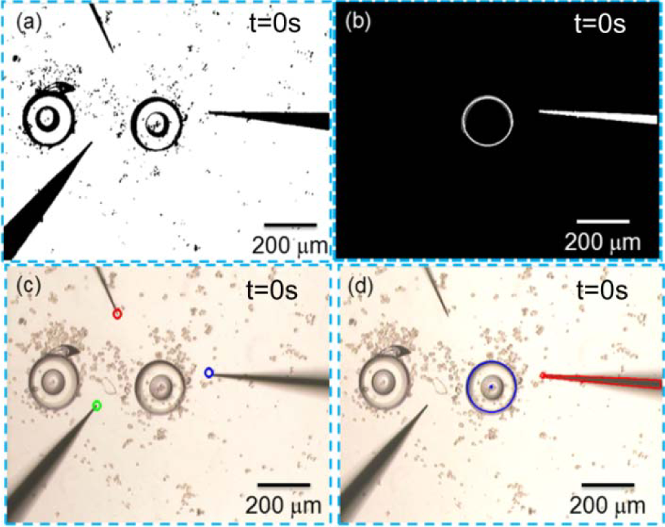
Image processing for the multi-manipulators' coordinated manipulation
To detect the orientation and position of the manipulators, we utilized Gaussian blur, canny contour detection and Hough line detection to detect the lines which formed the contour of the manipulator. As shown in Figure 13(d), after the detection of the line and image processing, we got the orientation of the manipulator and the X-Y position of the glass pipette tip. According to the information of the lines, including their length, angle and slope, the angle of the manipulator was figured out. The orientation of the manipulator was the direction in which the two lines became closer. To get the depth information of the manipulator, we touched the dish bottom with the tip of the manipulators to record the initial position in the Z direction and tracked the motion to calculate the relative position during manipulation. To realize the detection of the main-manipulator state, the vision system recorded the number of the picked donuts and calculated the distance between them and the tip. As shown in Figure 14, the picked donuts changed the contour of the main-manipulator and the distance was calculated based on the Hough line transform. As a whole, through the strategy of triggering, the manipulator position information and the manipulation distance information, we achieved sensing and coordinated manipulation with vision feedback.
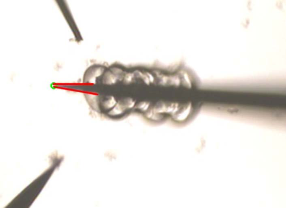
Detection of the distance between the glass pipette tip and the last picked donut
The effect of the occlusion was very important for the location of the donuts and the vision system's robustness. In our method, most of the donuts dispersed and lay flat in the bottom of the dish. Through the filtering with the dimension and the posture of the donuts, we neglected the donuts which leaned in the dish and only marked the eligible donuts. It decreased the occlusion effect and also made it easy to locate the inner hole of the donut. To evaluate the robustness of the vision feedback system, we acquired the feedback data to calculate the image processing errors. As shown in Figure 15(a), we evaluate the displacement data of the stationary donut. The error in locating the centre of the donut was around two pixels, which was about 5 μm under the X4 objective lens. As shown in Figure 15(b), the manipulator repeated the back-and-forth movement with vision feedback. The image processing error during movement was around three pixels, which was about 7.5 μm the under X4 objective lens. Since the dimension of the 2D components for micro-assembly was around 200 μm, an image processing error of less than 10 μm was acceptable during micromanipulation.

Image tracking result of the 2D component and the micromanipulator
5. Micro-assembly of the cellular micro-channel with multi-robotic coordinated manipulation
5.1. Micro-assembly of the donuts embedding NIH/3T3 cells
We set up the experiment to realize the bottom-up assembly of the cellular vascular-like micro-channel with the rail-guided micro-robotic system. As shown in Figure 16, the 2D donuts (as the assembly components) were prepared in the dish and monitored by the vision feedback system. The outer diameter, inner diameter and thickness of the fabricated donuts were 200 μm, 100 μm and 70 μm, respectively. As shown in Figure 16(a) andFigure 16(b), the up-down micro-assembly with the main-manipulator was performed once the system finished the initialization. Figure 16(c) to Figure 16(f) show the frequent switching of different coordinated manipulation strategies during micro-assembly to adjust or compact the assembled donuts. As a result, the postures of the assembled donuts were optimized and aligned as an array. After regulating the expected 2D components on the main-manipulator, the secondary UV cross-linking was utilized to connect the donuts as a whole micro-channel. In the experiment, the UV exposure for the first cross-linking and in order to fabricate the 2D donut was around 0.5 s, while it was around 1 s for the secondary cross-linking. Since the exposure time is short, the damage caused by the UV to the cells can be neglected. After changing the buffer solution, the sub-manipulators cooperated to release the micro-channel from the main-manipulator, as shown in Figure 16(g). The released micro-channel can be co-cultured in the incubator to become a vascular-like tissue.

Micro-robot-team assembly of the vascular-like micro-channel
5.2. Observation of the cellular micro-channel
With the micro-robot-team coordinated manipulation, we succeeded in the fabrication of micro-channel embedding NIH/3T3 cells inside. The dimension of the micro-channel can be regulated as expected. As shown in Figure 17, one of the assembled cellular micro-channels with an outer diameter of around 400 μm and an inner diameter of around 200 μm was observed both before and after release. The micro-channel was stained and observed under fluorescent light to check the NIH/3T3 cells. The experiment normally lasts 30 minutes, depending on the length of the micro-channel that we expected, and around 80% of the cells were alive in the donut after assembly. After the release of the micro-channel from the main-manipulator, the 3D view of the micro-channel was acquired with the confocal microscope and the total length of the micro-channel was around 1.5 mm, with 16 donut layers.

Observation of the cellular vascular-like micro-channel
6. Conclusion
We presented the fabrication of the cellular vascular-like micro-channel with coordinated manipulation among multi-micromanipulators. The rail-guided micro-robotic system was developed with modular micromanipulators and the concentric movement along the rail significantly improved the coordinated manipulation's flexibility. The cross-linkable hydrogel was utilized to embed the cells as the 2D components for assembly. Through the designed coordination strategies, the bottom-up assembly of the cellular micro-channel was achieved. After the evaluation of the micro-assembly's efficiency, the improved micro-assembly with vision feedback was carried out and a micro-channel embedding NIH/3T3 cells was demonstrated. This rail-guided micro-robot-team system provides a new concept for high-efficiency micromanipulation and the further development of more complex coordinated manipulation will be studied in the future.
Footnotes
7. Acknowledgments
This work was supported by the National Natural Science Foundation of China under grant 61375108 and the ‘111 Project’ under Grant B08043.