
Abstract
More and more humanoid robots are used in human society, and they face a wide variety of complicated manipulation tasks, which are mainly to be achieved by their anthropomorphic arms. Obstacle avoidance for the anthropomorphic arm must be a fundamental consideration to guarantee the successful implementation of these tasks. Different from traditional methods searching for feasible or optimal collision-free solutions for the anthropomorphic arm, a global obstacle-avoidance map for the whole arm is proposed to indicate the complete set of feasible solutions. In this map, the motion of the arm can be appropriately planned to intuitively control the configuration of the arm in motion. First, the cubic spline function is adopted to interpolate some well-chosen path points to generate a smooth collision-free path for the wrist of the anthropomorphic arm. Second, based on the path function of the wrist, the time and the self-rotation angle of the arm about the “shoulder-wrist” axis are used to parameterize all possible configurations of the arm so that a global two-dimensional map considering the obstacle avoidance can be established. Subsequently, a collision-free self-rotation angle profile of the arm can be well planned. Finally, the joint trajectories of a specific anthropomorphic arm, which correspond to the planned path of the wrist and self-rotation angle profile of the arm, can be solved on the basis of the general kinematic analysis of the anthropomorphic arm, and the specific structure. Several simulations are conducted to verify that the proposed collision-free motion planning method for anthropomorphic arms has some advantages and can be regarded as a convenient and intuitive tool to control the configuration of the anthropomorphic arm in motion, without collision with obstacles in its surroundings.
1. Introduction
As many researchers and scholars have pointed out, robots are gradually being involved in our society, getting closer to our lives, interacting with us and helping us achieve a variety of chores in our daily lives. Due to the similarity in appearance with humans, humanoid robots are favoured in many household, medical and healthcare applications, and play an important role in the service robot family. As for the service function of humanoid robots, they must have two fundamental capacities: locomotion and manipulation. Locomotion is usually implemented by the robots' legs, and manipulation tasks are generally done by their arms, which are anthropomorphic. When it comes to the manipulation and motion planning problems of anthropomorphic arms, an important issue is obstacle avoidance, which is the research topic of this paper.
The existing motion planning methods considering obstacle avoidance for redundant manipulators can be divided into three major categories: path planning in configuration space (C-space), artificial potential field, and gradient projection method (GPM). C-space path planning is a generic and global planning method for various robots, which is employed widely. It comprises C-space obstacles which are characterized by the collection of configurations which yield collisions with obstacles. Path planning in C-space thus usually involves the construction of C-space obstacles for a specific manipulator and searching for a collision-free path between the start and goal configurations in the global C-space model. Due to the high-dimensional property of the configuration space of redundant manipulators, the most effective kind of technique is sampling-based C-space planning, two typical examples of which are the PRM [1, 2] and the RRT [3, 4] techniques. However, because the specific kinematic model of a redundant manipulator is not considered in searching for a collision-free path in C-space, the resulting motion process of the whole arm cannot be predicted in advance. In addition, the computation of this method is time-consuming due to the high-dimensional configuration space. The artificial potential field approach does not construct a global C-space model, but rather a differentiable real-valued function, termed a potential function of joint variables, which guides the motion of the manipulator. The potential includes two components: an attractive component which pulls the manipulator towards the goal state, and a repulsive component which pushes the manipulator away from the obstacles. The gradient of the resultant potential function points in the direction that locally maximally increases the potential, which can be used to compute the collision-free path from the start point to the goal point by applying the corresponding gradient descent [5, 6]. However, this gradient-descent approach does not guarantee a solution to the problem. It is also prone to reaching a local minimum of the potential to result in failing to reach the goal state [7]. Another local optimization method, gradient projection method, is based on the Moore-Penrose pseudo-inverse of the Jacobian of redundant manipulator, and its solution can be divided into minimum norm solution and null-space solution at the velocity level. The former can force the end-effector of the manipulator to follow the desired velocity at a minimum joint velocity, while the latter allows the manipulator to optimize some obstacle-avoidance criterion by its self-motion, which does not affect the motion of its end-effector. Many performance indices on obstacle avoidance have been proposed to allow the redundant manipulator in motion to avoid obstacles as far as possible [8–11]. However, similarly to the artificial potential method, this local optimization method is also prone to making a redundant manipulator become stuck in some local minima. In addition, the two local methods cannot predict and control the configuration of the arm in motion, which is very significant for the anthropomorphic arm.
Taking these disadvantages into account, in this paper a generic framework of collision-free motion planning is proposed for anthropomorphic arms, which is a special group of redundant manipulators. In contrast to traditional collision-free motion planning methods to find feasible or optimal solutions, in this framework we try to create a global map for an anthropomorphic arm indicating the information on all feasible and unfeasible configurations of the arm. On the basis of this, a feasible route from the original configuration to the goal configuration can be easily planned in the feasible region of the created map. What is most appealing is that the planned route is highly intuitive, which means the user can easily imagine the detailed motion process of the arm corresponding to the planned result in advance, and can conveniently modify the route if the planned result does not meet expectations. This advantage of the proposed method in intuitiveness and convenience is the main novelty and unique feature of this paper. It is also worth noting that the proposed motion planning method is suitable for various anthropomorphic arms due to common or similar geometry. Thus, the method is endowed with the advantage of generality.
2. Some statements on the research issue
The research issue we discuss here is how to make an anthropomorphic arm achieve a successful reaching movement without collision with obstacles in its surroundings, as illustrated in Figure 1. The orientation of the hand of anthropomorphic arm is not considered in this paper; we are concerned rather with the position of the wrist. When the wrist is steered towards the goal position, we should not only keep the wrist away from the obstacle but also prevent the whole arm from approaching the obstacles, that is, the geometry of the whole anthropomorphic arm needs to be considered. Since different kinds of anthropomorphic arms have similar or almost the same geometry, it is possible to propose a unified motion planning framework for different anthropomorphic arms, which is one major contribution of this paper. In order to facilitate the detection of collisions between an anthropomorphic arm and obstacles, some simple bounding volumes are adopted to encapsulate them as their approximate geometrical representations. Here, due to similarity in shape and inexpensive computation [12], the sphere-swept lines, one type of sphere-swept volume commonly termed “capsules”, are used to approximately represent the upper arm and lower arm. Specifically, the capsule for an upper arm can be generated by sweeping a sphere of appropriate radius along the line segment between the centres of the shoulder and elbow joints. Likewise, the capsule for a lower arm would be the resulting volume of sweeping an appropriate sphere along the line segment between the centres of the elbow and wrist joints. Since the collision detection between any two sphere-swept volumes can be converted to conveniently comparing the distances between their inner primitives, such as points, lines, and rectangles, against the sum of their radii, we also employ sphere-swept volumes to represent obstacles. It is obvious that any complex sphere-swept volume can comprise some basic sphere-swept points, namely spheres. Without loss of generality, we assume the sphere is the basic geometrical element for describing obstacles.
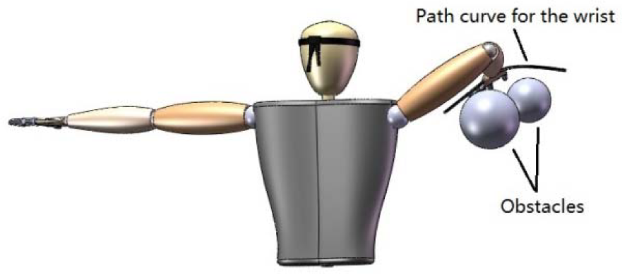
Reaching movement of an anthropomorphic arm without collision with obstacles
3. Collision-free motion planning for anthropomorphic arms
In this section, the proposed general collision-free motion-planning method for anthropomorphic arms will be introduced in detail. This method has a total of three steps. First, find an appropriate collision-free path only for the wrist of the anthropomorphic arm. Second, construct a complete global two-dimensional map for the whole arm, including feasible regions and forbidden regions, and plan a reasonable route in the feasible region. Finally, find solutions for the joint trajectories of the anthropomorphic arm corresponding to the planned route in the second step. In the following subsections, the three steps will be introduced in turn.
3.1. Finding a collision-free path for the wrist of the anthropomorphic arm
According to the assumption about the obstacles mentioned in section 2, the obstacles in the workspace of an anthropomorphic arm can be represented by a set of various spheres. Here, as an example, two spheres of different radii are employed as the obstacles in the environment, as shown in Figure 2. Given the start point and goal point of the wrist, our aim is to find a proper spatial path connecting the two points without any intersections with the two spheres. A great many research results from the field of neurophysiology show that human arms are inclined to perform a voluntary unconstrained reaching movement along a straight line rather than along other paths in free space [13, 14]. According to this conclusion, it is assumed that anthropomorphic arms should achieve a reaching movement along a straight line segment from the known start point to the goal point in space if the line segment does not intersect with any obstacle. A natural question then arises: how to design the path of the wrist if the line segment goes through some existing obstacles? Usually, we may use some via points in space that the planned path must pass through to control the shape of the path in order to avoid the obstacles. Different ways of choosing a set of via points will result in distinct feasible paths. Here, a convenient approach is proposed to obtain these via points.

Diagram of a collision-free path for the wrist of an anthropomorphic arm
As illustrated in Figure 2, line segment SG goes through both the obstacle spheres, and the Cartesian coordinates of the centres of the spheres,

where upper-case letters indicate vectors and lower-case letters denote scalars. The symbol ‖ ‖ means the magnitude of vector, and the symbol ⋅ refers to the dot product between vectors.

δ can be viewed as a parameter to control the distance

where

Note that, when the three cubic spline functions pass through the same via point, the time,

In addition, taking the actual initial and final velocities of the anthropomorphic arm motion into account, some additional boundary conditions are added for these spline functions:

Specific derivations of these spline functions can be obtained from [15], and thus are not presented here. By now, the spatial and temporal attributes of the planned collision-free path are both specified according to (1). Note that the proposed method is only suitable for cases in which the obstacles are distributed sparsely. Searching for collision-free paths in a complicated environment is still an open area for researchers, which is not the emphasis of this paper. Fortunately, the proposed global motion planning method for anthropomorphic arms can be effective based on any collision-free paths for the wrist. The creation of collision-free path used here is just a simple example for the introduction of the whole method.
3.2. Constructing a global obstacle-avoidance map for the whole anthropomorphic arm
After a specific path of the wrist of the anthropomorphic arm as a function of time is determined as in the preceding subsection, a two-dimensional global obstacle-avoidance map for the whole anthropomorphic arm is created. Each of the obstacles will generate a forbidden region in the map. The remaining regions of the map, apart from these forbidden regions, comprise the feasible region.
As shown in Figure 3, a simple triangle,
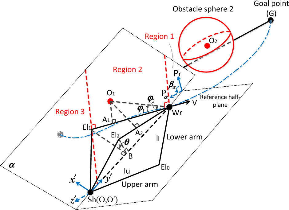
Diagram of the relationship between the arm and the obstacle sphere
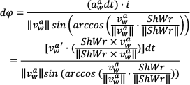
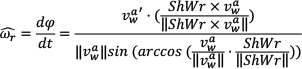
Keeping the position of the wrist static, the angle of the self-rotation can be regarded as a simple parameter to represent the configuration of the arm. Naturally, a reference configuration needs to be defined to calculate the specific angle value of a particular configuration of the arm. Here, the half-plane determined by vectors ShWr and V is defined as a reference plane for the arm, that is, the angle value of the self-rotation is zero when the arm is on this half-plane. V is the instantaneous linear velocity of the wrist. So, the reference configuration of the arm at every path point can be easily determined after the path of the wrist is defined. Obviously, the reference configuration changes as the path point varies. In fact, the defined path provides a complete and continuous reference system for the configuration description of the whole arm. In order to calculate the angle value between the reference half-plane and another half-plane containing the arm, that is, the angle of self-rotation of the arm, the direction of a half-plane is defined by the cross product of vectors X and ShWr, where X indicates any vector in the half-plane, the tail of which is on line segment ShWr. According to this definition, the unit direction vector of the reference half-plane,

where symbol × indicates the cross-product between vectors. It can be noticed that the wrist velocities are equal to zero when the arm is at the start or goal point. So, in order to ensure the consistency of the reference half-plane, we choose the reference half-plane of the arm at the moment,

The positive direction of the self-rotation of the arm is defined by the right-hand rule. Specifically, providing that the right-hand screw direction is the self-rotation direction, the self-rotation angle is positive if the direction of the thumb is along the direction of vector ShWr. Therefore, when the triangle of the anthropomorphic arm is on the half-plane α, the self-rotation angle,

As the forbidden region of the arm for an obstacle sphere is symmetrical about the half-plane α, the plane will be used as a reference half-plane to calculate the specific range of the unfeasible self-rotation angle for the arm. As shown in Figure 3, the arm triangle
Using the lower arm (the situation of the upper arm is similar), with two perpendiculars of El1Wr drawn on plane α from points El1 and Wr, respectively, plane α can be divided into four parts: its border line ShWr, and regions 1, 2, 3. When point
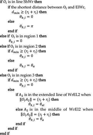
Next, the specific algorithms for

Set

Assume
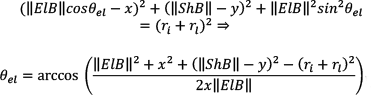
The algorithm for calculating the shortest distance between a point and a line segment has already been introduced in our previous paper, [11]; therefore, it is not presented again here due to limited space. Based on formulas (4) and (5) and algorithm (3),
With regard to the algorithm of calculating the shortest distance between a point and a line segment, it has already been introduced in our previous paper [11]. Therefore, it is not presented again here due to the limited space. Based on formulae (4) and (5) and algorithm (3),
Then, we construct a two-dimensional map whose horizontal axis is the time and whose vertical axis is the self-rotation angle of an arm. Since the relationship between the position of the path point and the time is defined according to (1), given the time, we can easily solve for the Cartesian coordinate of the corresponding path point of the wrist. So, a point on the map represents a specific configuration of the arm when the centre of the wrist is at a certain path point. For each path point of the wrist, there is an unfeasible configuration range of the arm, as (6). Therefore, for each obstacle sphere, there is a continuous forbidden region for the arm. As shown in Figure 4, there is one red forbidden region and one blue forbidden region caused by the obstacle spheres 1 and 2 respectively, and the remaining region of the map can be defined as feasible regions where the arm does not collide with any obstacles. Based on the created map, any continuous collision-free self-rotation angle profile can be planned within the feasible regions, as in the profiles above the blue forbidden region or below the red forbidden region shown in Figure 4. The feasible regions between the two forbidden regions are unavailable due to their incomplete connectivity along the time axis.

An obstacle-avoidance two-dimensional map for the anthropomorphic arm

When the obstacle-avoidance map dependent on the path of the wrist is created, the complete motion process of the arm will be uniquely determined after the suitable self-rotation angle profile in the map is planned. Different self-rotation angle profiles will yield different motion processes of the arm. Since the self-rotation angle directly reflects the extent of the rotation of the arm about the “shoulder-wrist” axis, the self-rotation angle profile can be regarded as a very intuitive tool to control the configuration of the arm in motion.
3.3. Solving for the joint trajectories according to the planned self-rotation angle profile
In this subsection, we will introduce how to solve for the specific joint trajectories for an anthropomorphic arm to realize the path of the wrist and the self-rotation angle profile of the whole arm planned in the previous two steps. First, we analyse the kinematics of anthropomorphic arms.
As shown in Figure 5, the absolute linear velocity of the wrist,

Diagram of kinematics analysis for anthropomorphic arms
According to the planned path for the wrist, the absolute velocity of the wrist at any time can be easily obtained:

Define the symbol γ as the angle between the upper arm and lower arm; it can then be obtained thus:

The unit direction vector of the half-plane, P, which the arm is on, can be calculated as:
According to the analysis mentioned above, the angular velocities of the shoulder and elbow joints can be solved by the algorithm as follows:

where
In order to calculate the angular velocity of the shoulder joint,

where


Next, the method of calculating the self-rotation angular velocity of the reference half-plane,

Diagram of the calculation of the self-rotation angular velocity of the reference plane
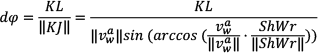
Drawing a perpendicular of

As
Then, we can easily obtain:
So, combining (10), (11) and (13), we can obtain
According to (8), (9), and (14), the angular velocities of the shoulder and elbow joints,

(a) Schematic diagram of the structure of a typical anthropomorphic arm. (b) Local diagram for the shoulder.
For the shoulder joint, the schematic diagram of angular velocities of the first three joints can be obtained as shown in Figure 7(b), derived from the structure of the shoulder shown in Figure 7(a). The transport angular velocity vector of the shoulder


where all vectors are described in terms of the base frame

Accordingly, the angular velocities of all joints for this typical anthropomorphic arm can be calculated by (15)-(18), which constitute a differential equation group. The differential equation group can be solved for the joint trajectories of the arm by employing the Runge-Kutta approach with given initial values of joint angles. For different anthropomorphic arms with distinct structures, when their link frames are established, their joint trajectories can be easily solved in a similar way.
4. Simulations
4.1. Constructing the obstacle-avoidance map for a typical anthropomorphic arm
Figure 8 shows a virtual 3D human upper-body model whose right arm has the kinematic model shown in Figure 7(a). The lengths of the upper arm and lower arm are 72.7 mm and 68.0 mm respectively. The task is to make the right arm perform a reaching movement from start point S (0, 60, 0)(mm) to goal point G (70, 100, 30)(mm). In order to achieve the movement successfully, the right arm must avoid two obstacles whose centres are located at (33, 63, 0)(mm) and (45, 95, 10)(mm), respectively, and whose radii are 20 mm and 15 mm.

A virtual 3D human upper body model
Because the line segment SG goes through the two spheres, a collision-free path for the wrist must be generated by using the method introduced in subsection 3.1. The positions of two via points can be calculated thus: V1(12.9, 83.4, 19.8)(mm) and V2(46.9, 75.7, 31.3)(mm). Then, the cubic spline function is employed to interpolate the four path points to generate a smooth path for the wrist, and the specific cubic spline function is obtained and rearranged as follows:
The spatial curve described by this cubic spline function is shown in Figure 8. The total time of the reaching movement is 5 s. Based on the path for the wrist, a two-dimensional obstacle-avoidance map for the whole anthropomorphic arm can be obtained as introduced in subsection 3.2, illustrated in Figure 9:

The obstacle-avoidance map for the typical anthropomorphic arm
In order to verify the correctness of the established obstacle-avoidance map, we select 20 key configurations,

Simulation results of the 20 key configurations,
Next, based on the effective obstacle-avoidance map, we can plan arbitrary self-rotation profiles for the arm. Two feasible and one unfeasible self-rotation profiles are planned according to the feasible region and forbidden region of the map. The purple self-rotation profile in the top feasible region is drawn by the cubic spline curve interpolating the four points: (0, 2.5), (1.5, 3), (2.5, 3.3), (5, 2), while the green profile in the bottom feasible region is represented by another cubic spline function interpolating the points: (0, 0), (2, −0.3), (3.2, 0), (5, −1.5). The black unfeasible self-rotation profile is a horizontal line from the start point (0, 2.5). According to these cubic spline functions of the three self-rotation profiles, each group of joint trajectories corresponding to each self-rotation profile can be obtained by adopting the method introduced in subsection 3.3. The frame sequences of the simulation results are shown in Figure 11. The first, second, and fourth rows are for the purple feasible solution, black unfeasible solution, and green feasible solution, respectively. The third and last lines show alternative views of the black and green profiles, respectively.

Simulation results of the three different self-rotation profiles shown in Figure 9. (a) The purple self-rotation profile. (b) The black self-rotation profile. (c) Another view of the black profile. (d) The green self-rotation profile. (e) Another view of the green profile.
According to the simulation results in Figure 11, the purple and green feasible self-rotation profiles can successfully keep the whole arm away from the obstacle spheres. The arm will collide with the bigger obstacle sphere from 1 s to 3 s if the arm performs the black self-rotation profile. So, all the results are in accordance with the constructed obstacle-avoidance map.
4.2. Comparison between the proposed method and a traditional method
In this part, for comparison, a traditional method, Gradient Projection Method (GPM), is used to plan the motion of the virtual arm to achieve the same reaching movement along the same path curve of the wrist shown in the preceding part. The differential equation of the joint velocity vector in the GPM is as follows:
where

means the gradient column vector of criterion H, which is the optimization objective function of GPM. k is the coefficient to control the optimization effect of the gradient vector. When k is set to zero, the solution is transformed into the minimum norm solution, which no longer optimizes the criterion H.
Here, H is defined as the shortest distance between the arm and the obstacles,

The initial joint vector is arbitrarily set as
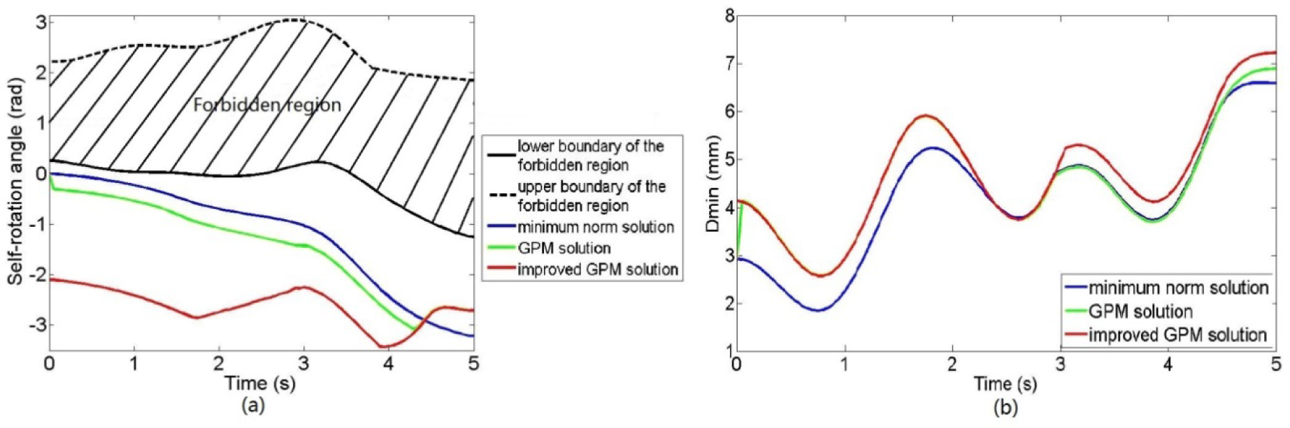
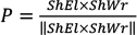
Comparison between three feasible solutions of the arm. (a) Self-rotation profiles. (b) Variation curves of criterion
As shown in Figure 12(b), the value of the
In addition to improving the GPM, another important advantage of the proposed obstacle-avoidance map is that it allows us to control the orientation of the anthropomorphic arm plane in order to produce more natural and human-like arm motion. As shown in Figure 11, after the path of the wrist is determined, the orientation of the arm plane can be arbitrarily adjusted within the feasible region to comply with some requirements at any moment. Specifically, the y-axis of the map indicates the rotation angle of the arm about the “shoulder-wrist” axis relative to the reference half-plane. We can simply modify the y coordinates of some key points through which the self-rotation angle profile must pass, to intuitively adjust the motion process of the arm if the previously planned result was not consistent with the habit of human arm motion, or did not meet the user's expectation. Obviously, in Figure 11, the green feasible solution is more human-like than the other two solutions.
Finally, we will draw a comparison between the proposed obstacle-avoidance map method and the GPM in terms of the computation effort and the likeliness of finding a feasible solution. It is not difficult to notice that solving for the joint trajectories in each of the two methods is realized by establishing the differential equation of the joint velocity first and then solving this equation with the Runge-Kutta approach. However, the difference between the two methods is that the differential equation is established based on the global information from the obtained map in the proposed method, and the similar equation is established based on the local information from the distance criterion, H. From formulae (15)-(19), we find that the joint velocities are obtained by simple operations among vectors and matrices in the proposed method; thus, it is an analytical method. In contrast, the GPM is a numerical method, due to the computation of the pseudo inverse of the Jacobian matrix. So, when the obstacle-avoidance map is established, the computation time of the proposed method will be shorter than that of the GPM in general if we ignore the computation effort for planning the self-rotation profile in the proposed method. For the likeliness of finding a feasible solution, the GPM will get into trouble and fail to complete the motion planning if there are any singularities during the planning. However, as a global method, it is easy to revise the self-rotation angles to allow the arm to avoid singularities to continue the motion planning in the proposed method. For instance, see the local diagram of the shoulder joint in Figure 7(b). If the axis of rotation for joint 3,
5. Conclusions
In this paper, a novel collision-free motion planning method for anthropomorphic arms has been discussed. A general concept of an obstacle-avoidance map for various anthropomorphic arms was proposed. After the collision-free path for the wrist of the arm was defined, the time and the self-rotation angle of the arm about the “shoulder-wrist” axis were employed to parameterize any possible configurations of the arm, producing a global two-dimensional obstacle-avoidance map. The effectiveness of the constructed map was verified by several simulations. It was also proven that the configuration of the arm in motion could be intuitively controlled by planning an appropriate self-rotation angle profile within the feasible region of the map to make the anthropomorphic arm motion more human-like. Compared with other traditional collision-free motion planning methods, the map actually provides us with a complete set of all feasible solutions, rather than only one particular solution.
The effect of the hand of the arm on the collision-free motion planning is not discussed in this paper. The obstacle-avoidance issue of the anthropomorphic arm with all the seven joints will be further investigated in future research.
Footnotes
6. Acknowledgements
The support for this research given by the National Key Technology R&D Programme (No. 2011BAF04B01) and the NSFC National Science Fund for Distinguished Young Scholars (No. 51125020) is greatly appreciated.