
Abstract
Water strider insects have attracted the attention of many researchers due to their power-efficient and agile water surface locomotion. This study proposes a new water strider insect-inspired robot, called STRIDE II, which uses new circular footpads for high lift, stability and payload capability, and a new elliptical leg rotation mechanism for more efficient water surface propulsion. Using the advantage of scaling effects on surface tension versus buoyancy, similar to water strider insects, this robot uses the repulsive surface tension force on its footpads as the dominant lift principle instead of creating buoyancy by using very skinny (1 mm diameter) circular footpads coated with a superhydrophobic material. The robot and the insect propel quickly and power efficiently on the water surface by the sculling motion of their two side-legs, which never break the water surface completely. This paper proposes models for the lift, drag and propulsion forces and the energy efficiency of the proposed legged robot, and experiments are conducted to verify these models. After optimizing the robot design using the lift models, a maximum lift capacity of 55 grams is achieved using 12 footpads with a 4.2 cm outer diameter, while the robot itself weighs 21.75 grams. For this robot, a propulsion efficiency of 22.3% was measured. The maximum forward and turning speeds of the robot were measured as 71.5 mm/sec and 0.21 rad/sec, respectively. These water strider robots could be used in water surface monitoring, cleaning and analysis in lakes, dams, rivers and the sea.
Introduction
The need for efficient, agile and multi-functional miniature robot locomotion systems often urges researchers to observe nature, analyse the working principles of biological systems and create ideas that can be implemented on miniature robotic systems. The research on biologically-inspired robotics both helps researchers to understand the dynamics of animals and gives us an idea for possible solutions that can be implemented to overcome challenging robotic locomotion problems [1]. Several examples of recent bio-inspired robotic locomotion works at the small-scale include gecko-inspired wall climbing robots [2–6], cockroach-inspired legged running robots [7], hummingbird-inspired flying robots with flapping wings [8, 9], and basilisk lizard-inspired water surface running robots [10].
Researchers have recently focused on the surface tension-driven locomotion of water-walking arthropods, such as water striders and fisher spiders [11–16]. The theory behind their lift, propulsion and drag mechanisms has been revealed and enabled the development of various robotic counterparts of these water-walking arthropods. Being inspired by these insects, there have been several studies to design and manufacture bio-inspired legged robots to achieve power efficient, fast, silent and stable legged locomotion on deep or very shallow water surfaces. Hu et al. [13] proposed a mechanical water strider powered by an elastic thread. Suhr et al. [17] developed a controllable water strider robot utilizing three piezoelectric unimorph actuators. Song et al. [18, 19] studied the numerical modelling of supporting legs by developing, respectively, a rigid-leg model and a compliant-leg model, and built a non-tethered water strider robot with two miniature DC motors and a lithium polymer battery. Suzuki et al. [20] showed two water strider robots with hydrophobic microstructures on the surface of the supporting legs driven by a vibration motor and a slider-crank mechanism, respectively. Shin et al. [21] and Zhou et al. [22] developed a water-jumping robot that was able to achieve a vertical jumping motion on the water surface with a latch mechanism driven by a shape memory alloy actuator.
In this work, to achieve efficient and fast legged propulsion, a new improved water strider robot, called STRIDE II, using a DC motor actuated four-bar elliptical leg rotation mechanism for water propulsion is proposed. This robot has concentric circular footpads that are designed, analysed and manufactured using laser-cutting to generate more lift force per unit area and greater stability when compared to STRIDE [19]. Moreover, the drag force model of the supporting structure and the propulsion mechanism are investigated and explained in detail. Finally, the robustness and the payload capacity of the robot are improved by the new design while keeping such features as the silent operation, slight subsurface disturbance and manoeuvring capabilities in both deep and shallow water of the older version, STRIDE [19]. This work is an extension and advanced version of our previous conference paper [23].
Problem Statement
Water strider insect locomotion exemplifies robust and efficient water surface walking because of the lift force mechanism involved, the low drag force on the supporting legs and the elliptical trajectory of the propelling legs. Therefore, these three features should be captured in the design of a water strider-inspired robot.
The lift force mechanism that a water strider insect dominantly uses is the surface tension force of the water, which is linearly proportional to the length of the supporting legs. Since the weight of the insect scales with its volume, if it is small in size, then the surface tension force is used as the lift force mechanism instead of buoyancy. To mimic the water strider insect, the robot should use surface tension as the dominant part of the lift force; therefore, the robot should have a relatively low weight and small size, but long legs to support itself on water. The water strider robot should also have enough payload capacity to carry on-board electronics, a power supply, actuators and sensors for control, autonomous locomotion and potential future applications, like monitoring water quality. On the other hand, for a robot to have a high payload capacity using surface tension, the required leg lengths might be unrealistically long. Therefore, the supporting structures are designed as concentric circular footpads, which increase the total length subjected to lift force while keeping the total area of the supporting structures relatively small. The lift force mechanism and the results are explained in detail in Section 3
The drag forces that a water strider insect experiences are relatively low at the supporting legs, enabling them to move rapidly and efficiently on the water's surface. This is due to the lift force mechanism of a water strider, which does not require the insect to break the water surface to stay afloat. Therefore, in order to claim that the designed robot is efficient for water surface locomotion, the drag force model for the robot should be established, as explained in detail in Section 4
In addition to the problems concerning lift force generation and drag force modelling, the propulsion mechanism of the robot should be designed so that the drag forces on the propelling legs, which are propulsion forces for the robot due to the momentum transfer principle [15], move the robot quickly. On the previous STRIDE, a miniature DC motor-driven actuating mechanism that was capable of creating sculling motions was used. The propelling wire-leg was formed into a rectangular loop and connected to the motor through a coupling. Therefore, the motion of the propelling wire-leg had a circular trajectory [19]. However, a more desirable means of propulsion employs an elliptical-like trajectory for the propelling wire-legs, as longer contact between the water surface and the propelling wire-legs is able to produce more propulsion in every driving stroke. Therefore, a four-bar mechanism, explained in Section 5.1.2, is designed which can create an elliptical-like trajectory for the propelling legs to efficiently increase the propulsion forces. The agility of the robot, its complexity and the availability of parts that are used in the propulsion mechanism should also be considered. Within these considerations, the final design of STRIDE II is shown in Figure 1.
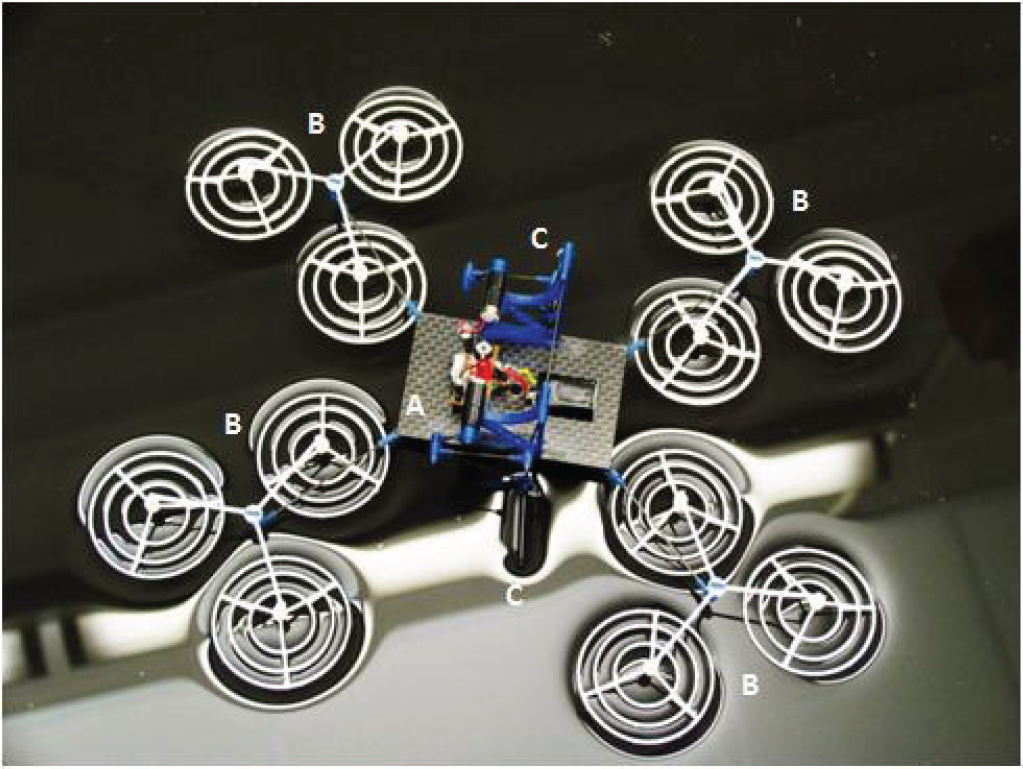
Photo of STRIDE II:
By applying the Young-Laplace equation to solve the air-water interface profile, a numerical model of the lift force generated on a cylindrical wire-leg due to the curvature of the free water surface was developed in [18]. It is known that the generated lift force increases as the length of the wire-leg increases (an optimized leg shape is necessary when the length of the leg exceeds 70 mm), and careful spacing is required to preserve the generated lift force when two wire-legs are arranged in adjacency [18]. Therefore, either by means of increasing the length of the wire-leg or by increasing the number of wire-legs, a larger lift force or a higher payload of the robot can be achieved. However, the increase in length is usually restricted by some fabrication issues, such as the difficulty in uniformly forming each wire-leg into the optimized shape. Also, the miniaturization of the robot always limits the maximum number of wire-legs.
To solve this trade-off, the design of concentric-circular footpads as shown in Figure 1 is employed on STRIDE II. A footpad with concentric circles is able to increase the effective length that is responsible for generating the lift force and at the same time saves space. According to [18], a 0.015 g/mm payload can be expected for Teflon® coated wire-legs. In order to obtain a payload of 15 grams, for example, a configuration of ten 100 mm long Teflon® coated wire-legs with a spacing of 12.4 mm between one another can be chosen. This spacing value conserves 95% of the lift force by preventing significant overlapping of the water dimples generated by the legs [18]. Hence, the area occupied by all the wire-legs is calculated as 11340 mm2, which means the unit area needed to carry 1 gram would be 756 mm2. On the other hand, the footpad design for STRIDE II has a lift force of 55 grams for a total of 12 footpads, where the occupied area is computed to be 16625 mm2, which means that the unit area needed to carry 1 gram would be 302 mm2.
In order to understand the lift force mechanism better, in this section a numerical model of the water surface near a partially submerged rigid cylinder - proposed before in [18] - is used to develop a model to analyse the lift force created by supporting footpads that consist of concentric circles as a new footpad geometry.
Two-dimensional Modelling
To simulate the lift force for a circular footpad, first, the cross-section of a footpad (which will be considered as a pattern with several circles submerged in water as shown in Figure 2), needs to be investigated using the models proposed in [18]. The number of circles that are submerged is equal to the number of concentric circles in the footpad.
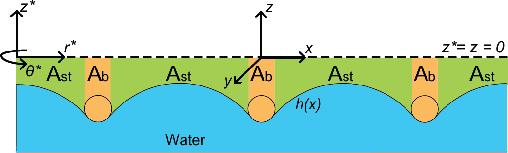
The side cross-section view of a three-concentric circle footpad. The areas Ab and Ast represent the areas that the footpad deforms because of its weight and the hydrophobicity of the leg material, respectively.
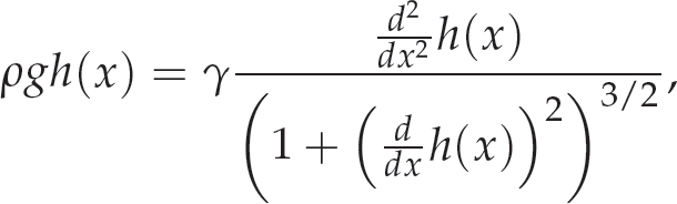
The weight of the water displaced by the footpad is identical to the amount of lift force the footpad generates. In other words, the weight of the water required to fill the volume bounded above by an undisturbed water surface (z = 0 line) and bounded below by the water-air interface is equal to the integral of the areas Ab and Ast along the 3D footpad geometry and is the total lift force. The buoyancy component and the surface tension component of the lift force are proportional to Ab and Ast, respectively [18, 21]. The shape of the air-water interface in the disturbed case is governed by the Young-Laplace equation. It is shown in [18] that this air-water interface profile (h(x)) can be calculated by numerically solving:
with the boundary conditions:


In these equations, ρ is the density of water, g is the gravitational constant, γ is the coefficient of the surface tension (0.072 N/m), θ c is the contact angle of the footpad material, ϕ is the submerge angle of the cross-section, and x0 = Rsin(ϕ) is the intersection point of the air-water interface and the footpad cross-section where R is the radius of the footpad cross-section. After calculating the surface profile using (1)–(4), the total lift force is calculated by integrating the profile around the centre of the footpad.
Similar to the model in [18], the 2D water surface profile analysis of a cross-section forms the basis of the concentric footpad lift-force calculation. The basic differences are the profile interference due to nearby concentric circles and the change of the coordinate system from Cartesian to polar coordinates. To begin the calculations, an h(x) profile is created using the 2D analysis in [18]. The radius of the material is specified here and a specific h(x) is created by solving the Young-Laplace equation. Next, this profile is modified for several numbers of concentric circles. The concentric circles' radii are compared with pre-defined “infinity” (the distance where the water surface depth reaches its original value - i.e., the dimple disappears and is estimated as 1 cm using [18] and observations) and the various interferences are calculated. A new modified h(x) is created for a given number of concentric circles. Figure 3 shows the water surface profile calculated in MATLAB for a footpad that consists of five concentric circles with four, nine, 13, 17 and 21 mm radii, respectively.

The simulation result of the water surface profile h(x) for a footpad with four, nine, 13, 17 and 21 mm radii concentric circles
The modified water surface profile consists of data from the centre of the concentric footpad to the outer undisturbed surface. This modified surface should be integrated along the footpad in order to find the lift forces. A coordinate system transformation is conducted in order to take the integral around the centre of the footpad. Figure 2 shows how this transformation is carried out.
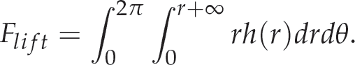
The polar coordinate system, (r*, θ*, z*), where the integral for the lift force of the footpad will be calculated, is placed at the centre of the footpad as shown in Figure 2. z = 0 is the undisturbed water surface. Since the water surface profile only changes with the distance from the centre of the footpad, h(x) will be directly transformed to h(r). Following the coordinate system transformation, a polar integral around the centre of the footpad is performed to calculate the total amount of lift force produced by the footpad:
To find the buoyancy component of the lift force separately, the area Ab should be integrated; therefore, the limits of the r integral should be changed. Similarly, for the surface tension component of the lift force, only the area At should be considered and the limits of the r integral should be adjusted appropriately.
The simulation results are calculated using the model described above and the experimental results are obtained by loading a single footpad with a platform that can carry a load. Several grams of sugar are placed on the platform above the footpad and the amount of weight that it can carry just before breaking the water surface and sinking is measured.
For the experiments, four different footpads with different numbers of concentric circles and different diameters were tried (8–42 mm, 14–42 mm, 8-26-42 mm and 20-32-42 mm). The diameter of the outer concentric circle is kept at 42 mm to keep the area bounded. The dimensions for these footpads are found by running simulations to maximize different parameters (Surface Tension/Buoyancy, Surface Tension, Total Lift × Surface Tension/Buoyancy, and Total Lift, respectively). The simulation and experimental results are shown in Table 1. The results show that the simulated lift force values are slightly lower than the experimental ones, except for the last footpad with three concentric circles with diameters of 20-32-42 mm. This overestimation is caused by the interference calculation part of the 3D model, which calculates where interference occurs and trims the interfered with parts. However, in reality the interference of the water surface profiles causes the slope of the water surface to be 0 at the intersections of the profiles seen in Figure 3, which would mean lower water surface levels at the intersection points, and hence which would cause an increase in the total lift force. On the other hand, the simulation assumes that the cross-sections of the footpads are circular, but in reality the cross-sections are rectangular. The sharp edges at the ends of the rectangles may break the water surface before the maximum lift force is achieved, creating a competing factor. These sharp edges are points where the pressure on the water surface increases. As these pressure localization points get closer to each other, they are grouped on a smaller area on the water surface. Hence, as the concentric circles are brought closer to each other, the actual payload capacity is unable match to the simulation results (which do not consider the sharp edges as a factor). This behaviour causes the water surface to break more easily than expected, which is the reason for the overestimation in the last row of Table 1.
Simulation and Experimental Lift Force Results

Simulation and Experimental Lift Force Results
The footpad with diameters 20-32-42 mm is chosen as the best design since it maximizes the lift force, which is the most significant quantity to be optimized. The total lift capacity of a 12 footpad robot would, therefore, be approximately 55 grams - more than necessary to carry on-board electronics, a 3.5 Volt battery, two miniature DC motors and two leg rotation mechanisms with a safety factor of approximately two.
The simulation results in [18] show that the surface tension-based lift force is directly correlated with the contact angle of the supporting leg material. However, the advantage of being hydrophobic diminishes for contact angles above 120 degrees, above which the lift force is approximately the same for any angle. The main reason behind this is that the surface tension force is limited by material properties if the material is hydrophilic or else is limited with a surface tension coefficient (0.072 n/m) if the material is hydrophobic. Hence, for materials with a contact angle above 120 degrees, the surface tension per unit length is almost equal to 0.072 N/m [24]. Therefore, the footpads are coated with a hydrophobic coating (Cytonix, WX2100™) with a contact angle of 145 degrees to obtain the best available surface tension force. The hydrophobicity of the leg enables us to maximize the lift force for a given geometry. This contact angle of 145 degrees is used in the simulations.
Analysis and Experiments on Robot Dynamics
When the robot is translating on water, the equation for its motion can be written as:

where m is the mass of the robot, a is its acceleration, FP is the propulsion force on the robot which arises from the drag forces acting on the two rowing wire-legs when they are driven backwards against the water with respect to the robot's body, and FR is the resistance force which comprises various drag forces acting on the supporting footpads. When these two forces are equal to one another, the robot achieves its terminal velocity.
Similar to a fisher spider [25], three physical mechanisms are potentially responsible for the drag forces acting on the robot:
Capillary-Gravity Wave Drag
For any partially submerged body moving at the water surface with a velocity greater than cmin = (4gγ/ρ1/4 ≈ 0.23 m/s, the minimum phase velocity of the surface waves will generate capillary-gravity waves that dissipate energy and resist the body's motion [26]. Here, g is the gravity, γ is the surface tension and ρ is the density of water.
Surface Tension Drag
When a partially submerged body is at rest on the water surface, the surface tension forces acting on the two contact lines on each side of the body are symmetric, and there is no horizontal resultant force. However, when the body moves, asymmetry of the surface tension forces occurs and the resultant force creates surface tension drag[25].
Hydrodynamic Drag
A moving, partially submerged body creates viscous drag consisting of a normal pressure component (form drag), a shear stress component (skin friction drag) and a trailing vortex wake component (interference drag). These three drag forces act over the whole of the submerged section of the body [27].
In the case of STRIDE II, the estimated velocity of the robot is well below cmin; thus, the capillary-gravity wave drag is not expected to contribute to the overall resistance to the robot's motion. In [24], it is shown that the maximum surface tension drag achieved before meeting water surface-breaking conditions is significantly less than the hydrodynamic drag. Therefore, it is asserted that hydrodynamic drag dominates the lateral resistance force on the robot.
The hydrodynamic drag is given in [27] as:

where ρ is the density of water, A is the reference area, CD is the drag coefficient including all contributions from the form drag, the skin friction drag and the interference drag, and U is the velocity of the robot with respect to the water. It is known that CD varies as a function of the Reynolds number, Re, of the object [27], which generally combines the fluid properties of density and viscosity, as well as the object's velocity and characteristic length. Although Re, and thus CD can vary greatly, the variation within a practical range of interest is usually small, so that CD is often treated as a constant [28]. Usually, Eq. (7) is applicable with CD as a constant when Re > 1000.
It is worth noting that CD is always associated with a particular surface area, A [29]. Here, this area is defined as the orthographic projection of the dimple's frontal area on a plane perpendicular to the direction of motion, which is:

for the cylindrical wire-legs, where h is the dimple depth and l is the length of the wire-legs; or:
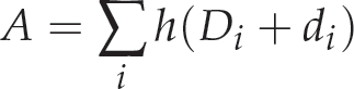
for the footpads, where Di and di are the outer and inner diameters of each concentric circle of the footpads, respectively. Figure 4 shows the defined reference areas of a cylindrical wire-leg and a footpad with three concentric circles.

(a) Schematics of the defined reference area of a cylindrical wire-leg: A = hl; (b) Schematic of the defined reference area of a footpad with three concentric circles: A = Σ i h(Di + di). U denotes the direction of velocity of the wire-leg or the footpad.
Note that the hydrodynamic drag has a simple quadratic relationship with U2. In the next section, experiments are performed to show the existence of this relationship and thus demonstrate the dominance of the hydrodynamic drag.
As mentioned earlier, when the robot is in motion, the drag coefficient CD stays constant if Re > 1000. Experiments are performed to measure this constant value of CD.
A passive robot platform with four sets of supporting footpads is built to conduct the experiments. In each experiment, an initial velocity is applied to the platform and its displacement with respect to time is measured using a video-tracking technique, shown in Figure 5(a). The results were then used to obtain the mean velocity and acceleration information by calculating the first and second derivatives in which the Savitzky-Golay filters were applied to smooth the data [30]. Figure 5(b) illustrates the experimental data acceleration with respect to velocity. The matching performance of the quadratic curve fitting implies a quadratic relationship between the acceleration and the velocity. Therefore, according to Eq. (7), it is reasonable to assert that the hydrodynamic drag serves as the primary resistance force for the footpads.

(a) Plot of experimental displacement data with respect to time. Savitzky-Golay filters were applied to smooth the data. (b) Plot of experimental data of acceleration with respect to velocity. The fitting model is y = ax2 and the R-square value of the fit is 0.9974. This quadratic relationship justifies the dominance of the hydrodynamic drag in the resistance forces of the footpads.
Since, in the experiments, no propulsion force is applied to the platform and the hydrodynamic drag is considered to be the only source of resistance, substitute Eq. (7) into Eq. (6):

Thus:
Given a from the experimental data and A calculated using Eq. (9), CD can be directly computed. Figure 6 shows the variance of CD with respect to Re. It is shown that CD varies slightly in the experimental velocity range (corresponding Re range: 1671–2833), which overlaps with the estimated velocity range of the robot. By averaging the results shown in Figure 6, 0.155 is chosen as an estimated value of the drag coefficient for the supporting footpads.
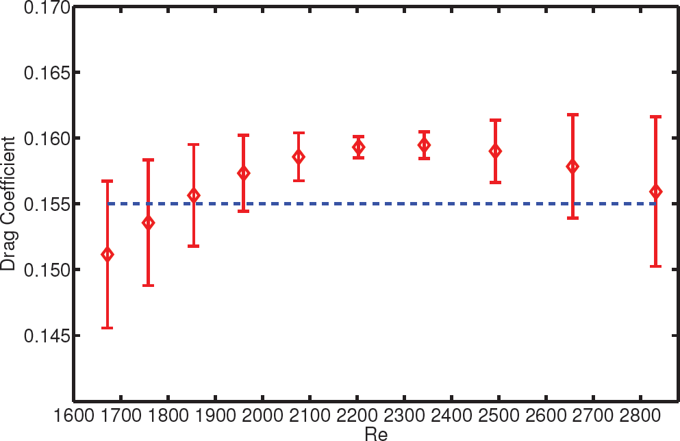
Plot of the experimental drag coefficient with respect to the Reynolds number. 0.155 is chosen to be an estimate of the drag coefficient for the supporting footpads of STRIDE II.
As discussed before, the calculation of the resistance force of the robot, FR, in Eq. (6), becomes fairly simple based on Eq. (11) and the experimental evaluation of CD. But the analysis of the propulsion force, FP, remains less clear, as the operating range of the rowing wire-legs' velocity is measured to range from 250 mm/s to 755 mm/s, which exceeds cmin ≈ 0.23 m/s. This fact implies that the capillary-gravity wave drag may become one of the sources of FP. However, Bush et al. [15] conducted experiments with high-speed video and particle-tracking and concluded that the water striders transfer momentum to the underlying fluid not primarily through capillary waves but rather through hemispherical vortices shed by their rowing legs.
To obtain knowledge of the terminal velocity of the robot, a hydrodynamic drag force of a general form D = 1/2ρAC D U2 is assumed to act as FP, where A is calculated as in Eq. (8) and C D is chosen as 0.09, an experimental drag coefficient for a streamlined half-body which closely resembles the shape of the dimple associated with the wire-legs [27]. Let a in Eq. (6) be set to zero and substitute the expressions of FP and FR into 6:

where Uw is the velocity of the rowing wire-legs with respect to the robot body, Ut is the terminal velocity of the robot, Aw and Af are the reference areas of the wire-legs and the footpads, respectively, and CDw and CDf are the drag coefficients of the wire-legs and the footpads, respectively. Equation (12) can be rearranged as:

Since Aw and Af can be calculated using Eq. (8) and Eq. (9), and CDw and CDf are, respectively, determined as 0.09 and 0.155, a quantitative relationship between Ut and Uw can be obtained:

Using this equation, the terminal velocity of the robot can be estimated given the velocity of the rowing wire-legs, which can be further calculated from the gear motors' speed (a controllable parameter).
Experiments were performed to acquire velocity data of the robot and the wire-legs. By video observation, the motor speed was first measured and was then used to calculate Uw. Ut was directly obtained by video-tracking, as shown by Figure 7. Table 2 shows all the data from five different measurements, from which an approximate agreement with Eq. (14) is revealed. These experiments are able to justify the conclusion of Bush et al. [15] that capillary waves do not play an essential role in the propulsion, although the waves are still observable due to the rowing action.

Plot of robot velocity with respect to time in one of the robot velocity measurements. A terminal velocity of 36.6 mm/s can be obtained from this plot.
Comparisons between experimental Ut and Uw values

Footpad Fabrication
It is noticed that, in order to obtain a high payload capacity, it is more desirable to use multiple relatively smaller footpads than a few large ones, as support from multiple loci is beneficial for a robot's static balance. This requires that the multiple footpads should be properly arranged in a well-balanced and space-saving configuration. Here, a tripod design as shown in Figure 8 is adopted. Each tripod consists of three concentric-circular footpads connected to a tri-beam with three ball and socket joints. When the tripod is mounted on the robot with the centre of the tri-beam fixed, the ball and socket joints are able to self-align each footpad parallel to the water surface. The design of the distances between each footpad complies with the careful-spacing to preserve 95% of the generated lift force [18].

Sketch of the tripod design for the footpads. Three ball and socket joints are employed to implement self-alignment.
The footpads are cut using a laser engraver (GCC, Venus) from a 1 mm thick Delrin® sheet and then coated with a super-hydrophobic material, fluorothane (Cytonix, WX2100™). All the other parts, including the tri-beam, the ball and socket joint and the truss are also formed by the laser engraver. Assembly is done by gluing.
In order to generate an elliptical-like trajectory for the rowing wire-legs, a crank-rocker four-bar mechanism is designed and used on STRIDE II, as shown in Figure 9(a). When the crank is continuously driven by the miniature gear motor, an elliptical-like motion is produced at the bottom vertex of the coupler triangle where the rowing wire-leg is mounted. The dimension design (Figure 9(b)) of the four-bar mechanism obeys three principles: (1) the contact between the rowing wire-legs and the water surface is maximized as much as possible so that more propulsion can be produced; (2) the rowing wire-legs will not break the water surface so that the supporting footpads will not be affected by the disturbance on the water surface; (3) Grashof's law is not violated: the sum of the lengths of the shortest and longest link is not greater than the sum of the lengths of the remaining two links. Figure 9(c) shows the simulation of the designed trajectory of the rowing wire-legs. When the rowing wire-leg is pushed down to 3 mm deep under the water surface, the length of contact can reach up to around 35 mm, which is about 2.5 times longer than that of the previous STRIDE [19].

(a) Sketch of the four-bar actuating mechanism with a miniature gear motor. (b) Significant dimensions (unit: mm) of the four-bar actuator. (c) Simulation of the trajectory of the rowing wire-leg. The origin is fixed at the locus of the gear motor.
The classical velocity analysis of a four-bar mechanism can provide the knowledge of the velocity of the rowing wire-legs. When the speed of the gear motor is set to be 150–450 rpm (which is experimentally decided as a proper range), the average linear velocity of the rowing wire-legs along the direction of the robot's motion while they stay in contact with the water surface is calculated to range from 250 mm/s to 755 mm/s.
The frame and all the joint parts of the actuating mechanism are fabricated using a rapid prototyping machine (3D Systems, Inc., Invision HR). The 20 mm long rowing wire-legs are formed by Teflon® coated stainless steel wires (diameter: 0.33 mm). The fabricated actuating mechanism, including the gear motor, weighs around 2.9 grams.
Two four-bar actuators with miniature gear motors (Precision Microdrives™, 206–101), a custom control board and a polymer Li-Ion battery (Powerizer, PL-651628-2C) take up the bulk of the weight of the robot body. To maximize the payload of the robot, the robot body itself and the connections between the supporting footpads and the body are designed to be as light and simple as possible. A 70 mm × 44 mm × 1 mm carbon fibre sheet is used as the main body of the robot. The two actuators are symmetrically attached on the two edges of the body by gluing. The control board and the battery are placed in the middle of the body and their positions are adjusted so that the centre of mass and the geometrical centre of the robot are co-located with each other. This guarantees that any unnecessary roll motion or motion of the robot can be avoided while the robot runs. Four sets of footpads are connected to the robot body, with four 50 mm long cantilevers made of carbon fibre beams with a small connector at each end. Figure 1 shows the fabricated STRIDE II, which weighs 21.75 grams.
On-board Electronics
To achieve more effective control, a custom control board is developed for STRIDE II. It includes a microcontroller (Microchip, PIC18LF2520), a motor driver (Freescale, MPC17C724), a voltage regulator (Analogic, AAT3221), an IR receiver (Vishay, TSOP36236), a timer (ST TS555), a trimming potentiometer (Bourns, 3223) and several resistors and capacitors. It is capable of power management, motor control and IR communication. The PCB is designed with the EAGLE layout editor (CadSoft Computer Inc.). The usage of SMD packaging for all the electronics helps to decrease the weight and volume of the board and hence maximize the payload of the robot.
Robot Experiments
The robot is controlled by using an IR remote. Figures 10(a) and 10(b), respectively, show a forward linear motion and a right-turning motion of the robot with speeds of 71.5 mm/s and 0.21 rad/s, respectively. No feedback control is applied; the voltage values for the motors that enable the robot to move in a straight line or with a predefined curvature are tuned beforehand.

Photo snapshots of STRIDE II in motion: (a) Forward linear motion at a speed of 71.5 mm/s. (b) Right turn at an angular speed of 0.21 rad/s.
The robot's power consumption and efficiency are calculated and presented in Table 3. Here, the motor efficiency is taken into consideration to obtain the input mechanical power to the actuators. Therefore, the calculated robot efficiency is based on the input mechanical power and output mechanical power rather than the input electrical power. The motors used have a fairly low efficiency (2–6% at the 150–450 rpm range), leading to excess power usage. This can be improved by using higher efficiency, lightweight motors. It is noted that the input and output mechanical power are in the order of microwatts, which implies that this robot can be operated at very low power.
Experimental Robot Power Consumption and Efficiency Results

As mentioned in Section 3, the utilization of concentric circular footpads rather than the wire-legs used in STRIDE [24] resulted in an increase in lift force per unit area from 1/756 grams/mm2 to 1/302 grams/mm2. In addition to the increase in the total area of the lift force-generating mechanism, this improvement resulted in a robot capable of carrying 55 grams (whereas STRIDE was only able to carry 9.3 grams). The self-aligning nature of the footpads also had a positive impact on improving the lift force; STRIDE suffered from fabrication imperfections that caused the wire-legs to be slightly different from one another, resulting in a lower payload capacity. The utilization of DC motors with four-bar mechanisms in STRIDE II allowed us to keep the elliptical trajectory of the rowing legs but eliminated the need for the high actuation voltage of the piezoelectric unimorphs used in STRIDE. Therefore, we were able to make an untethered, on-board powered robot working with lithium-polymer batteries. The resulting new version was able to move faster on a straight line, achieving a speed of 7.1 cm/s compared to the 3 cm/s straight-line speed of STRIDE. However, the addition of the footpads and on-board electronics resulted in a heavier, wider robot, with a slower turning velocity of 0.21 rad/s compared to the 0.5 rad/s turning speed of STRIDE.
Conclusion
In this paper, a STRIDE II robot that uses concentric circular footpads and elliptically rotating propelling legs is analysed and developed. The robustness of the robot is enhanced when compared to previous water strider robots, its lift force model is established and the dynamic forces like drag and the propulsion force that STRIDE II experiences are modelled. The use of concentric circular footpads as the supporting structure increased the payload capacity of the robot by a factor of four. Two DC motors with four-bar mechanisms are used for propulsion, enabling the propelling leg to have an elliptical trajectory which supplies more propulsion force compared to a circular trajectory. The static and dynamic forces applied on the robot body are investigated and models for the forces that the robot experiences are established and supported with experimental data. The autonomous control of single and multiple water strider robots is the next planned step. In the future, this robot could be used as an educational or toy robot, or else swarm of these robots can be used for various applications such as water quality-monitoring on dams, lakes and the sea.
Footnotes
7.
The authors would like to thank all the NanoRobotics Laboratory group members for their invaluable discussions.