
Abstract
Micro-robotic systems are increasingly used in medicine and other fields requiring precision engineering. This paper proposes a piezoelectric impact-type rotary actuator and applies it to a millimetre-size robot controlled by a hardware neuron model. The rotary actuator and robot are fabricated by micro-electro-mechanical systems (MEMS) technology. The actuator is composed of multilayer piezoelectric elements. The rotational motion of the rotor is generated by the impact head attached to the piezoelectric element. The millimetre-size robot is fitted with six legs, three on either side of the developed actuator, and can walk on uneven surfaces like an insect. The three leg parts on each side are connected by a linking mechanism. The control system is a hardware neuron model constructed from analogue electronic circuits that mimic the behaviour of biological neurons. The output signal ports of the controller are connected to the multilayer piezoelectric element. This robot system requires no specialized software programs or A/D converters. The rotation speed of the rotary actuator reaches 60 rpm at an applied neuron frequency of 25 kHz during the walking motion. The width, length and height of the robot are 4.0, 4.6 and 3.6 mm, respectively. The motion speed is 180 mm/min.
1. Introduction
Micro-robotic systems are currently attracting much research interest. Most of these systems have been applied in medicine and other fields that require precise manipulation. These robots have a capsule or slim-line shape to allow movement inside blood vessels [1, 2]. Moreover, insect-type or fish-like micro-robots have been researched [3, 4]. In the future, insect-type micro-robots may eventually mimic the behaviour of industrially useful insects such as honeybees and silkworms. However, very few insect-type robots can operate at the level of living organisms. Although micro-robots with legs are being researched for use under water [5, 6], micro-robots with the ability to walk on sand are few. Developmental obstacles include miniaturization of the mechanism, low energy requirements for ensuring long lifetime, and realization of the flexibility inherent in living organisms.
Conventional actuators are manufactured by mechanical machining, which is generally not suitable for fabricating small actuator structures. To overcome this limitation, researchers have developed micro-electro-mechanical systems (MEMS) technology, based on the integrated circuit production process [7].
Using a range of fabrication methods, researchers have developed a diverse suite of actuators including electrostatic actuators [8], electromagnetic actuators [9], shape memory alloy (SMA) actuators [10, 11], and piezoelectric actuators [12]. The electrostatic type is easily miniaturized but generates only a small force. In contrast, electromagnetic actuators can generate large forces, but their compositional elements (the magnetic core and coil element) are difficult to miniaturize. SMA and piezoelectric actuators realize actuator motion by shrinkage and expansion. However, since SMA is driven by heat power, much of the operating time is used in heating and cooling processes, limiting the response time as miniaturization improves. In contrast, piezoelectric actuators operate under an applied voltage and respond much more rapidly than SMA actuators. Some specially designed actuators have been reported; for example, those that directly use the vibration of the piezoelectric device [13]. The impact-driven linear actuator operates by friction and inertia [14]. These actuator structures are both simple and suitable for miniaturization, but their displacement is smaller than that of conventional SMA. Moreover, few mechanisms can generate the required rotational motion; thus, these structures have limited practical use.
Robots are conventionally controlled by digital systems constructed using microprocessors and software programs. While a pre-programmed digital system exerts adequate control in a specified environment, it may not appropriately respond to unpredictable events. More flexible control is provided by artificial neural networks [15]. For example, the walking motions of insects are governed by simple neural networks. Moreover, living organisms are flexible and sensitively respond to accidental events. For these reasons, artificial neural network control system is a preferable choice in micro-robot design. Most artificial neural networks are implemented by a software approach based on mathematical calculations [16]. However, with this approach, even simple neural networks consume vast amounts of time and physical computer resources. Therefore, several researchers have implemented neural networks in hardware [17], which can continuously process nonlinear operations at high speed.
We have previously used MEMS technology to fabricate insect-type micro-robots [18, 19]. These robots were equipped with SMA-based artificial muscle wires. They walk on six legs via footsteps controlled by pulse-type hardware neural networks (P-HNM), which in turn are controlled by an analogue circuit. However, the artificial muscle wire actuator had several problems: large power consumption, slow speed and a control pulse of the order of 1 s, requiring a large circuit constant for the control circuit. To overcome these problems, we built the control circuit into CMOS IC [20] and connected the capacitor to the exterior of the IC.
In this paper, we develop an impact-type MEMS rotary actuator using a piezoelectric element and apply it to a millimetre-size robot. The developed actuator demonstrates high-speed motion and low power consumption. The circuit constant is reduced by the high actuator pulse frequency. The hexapod legs enable insect-like walking on uneven surfaces. The walking is controlled by a P-HNM; in this case, an artificial intelligence (AI) system. The walking motion of the developed robot is confirmed in this study. In future developments, the entire control circuit will be embedded in a single IC chip.
2. Structures and systems
2.1. Piezoelectric impact-type MEMS rotary actuator
The fabricated piezoelectric impact-type MEMS rotary actuator (1.0 mm × 4.4 mm × 3.2 mm) is shown in Figure 1. The diameter of the rotor is 2 mm. The operating mechanism is simple. A piezoelectric element is affixed outside the rotor and is held in the cavity within the body frame. The impact head is attached to the piezoelectric element. The impact head and the rotor, which realize stable rotational motion, are shown in Figure 2. The impact head contains a bump structure for impact and two holding parts. The purpose of the holding parts is to hold the rim structure in the rotor, thereby stabilizing the position of the impact point. The piezoelectric element thus arranged is expanded by electrical pulses, which impact on the rotor to generate rotary motion.
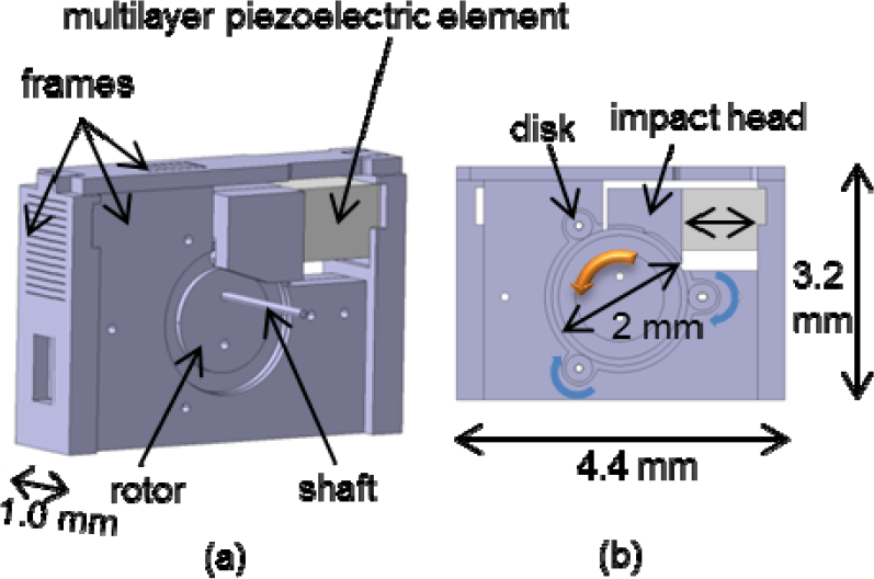
Mechanism of the designed piezoelectric impact-type MEMS rotary actuator. (a) Overall view, (b) cross-sectional view

Design of impact head and rim structure of the rotor. (a) Inside of the impact head, (b) rim structure of the rotor
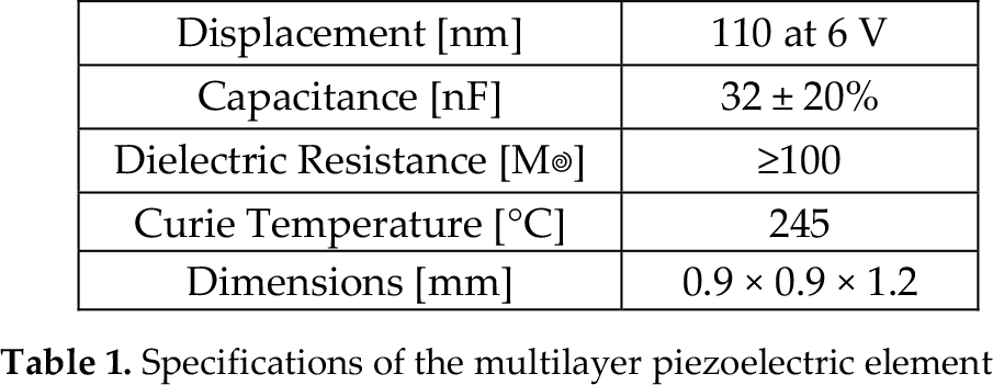
The rotor is held in place by three disks of 0.4 mm diameter; this arrangement reduces the friction between the rotor and the frame. A multilayer piezoelectric element is chosen on account of its low drive voltage. The specifications of the multilayer piezoelectric element are shown in Table 1.
Specifications of the multilayer piezoelectric element
The frames, impact head, three disks and actuator rotor are made of single-crystal silicon wafers fabricated by micromachining. The silicon wafer used for the body frames, rotor and impact head was 400 μm thick, whereas that used for the disks was 200 μm thick. The silicon wafer was washed, and aluminium was deposited to a thickness of approximately 0.1 μm by physical vapour deposition, followed by coating with a photoresist. The designed pattern was exposed to the resistant film and developed by soaking in the developer. The aluminium film on the specimen was then chemically etched, leaving an imprint of the designed pattern. The washed and dried specimen was dry etched by high-aspect-ratio induced coupled plasma etching combined with a Bosch process [21]. The part was obtained after removing the aluminium film and washing. To form the complex structures (cavity, bump, holding part and rim structure), this process was repeated for the body frame to which the multilayer piezoelectric element, impact head and rotor part are attached. The fabrication process is shown in Figure 3. The fabricated parts were assembled by hand into the piezoelectric actuator. The frames were assembled by inserting the jutting parts into the grooves.

Fabrication of the MEMS components
2.2. Millimetre-size robot
The developed rotary actuator is applied to a millimetre-size hexapod robot, on which the three leg parts on each side of the developed actuator are connected by a linking mechanism. Figure 4 is a schematic illustration of the robot. The width, length and height of the robot are 4.0, 4.6 and 3.6 mm, respectively. The legs are fabricated by micromachining. The front and rear legs move counter to the centre leg. To ensure that the robot remains parallel with the ground, the central leg is made shorter than the other legs. The central legs are connected to the rotor by a tungsten carbide shaft, while the outer legs are held by shafts attached to the body frame. To obtain robot parts, MEMS photolithography was repeated on both surfaces of the wafer.

Mechanism of the designed millimetre-size robot
2.3. Hardware neuron model
The insect-type robot must realize flexible control similar to that of living organisms. To this end, the developed robot is controlled by a hardware neuron model built from a single-cell body model. This analogue circuit reproduces the functions of biological neurons as a P-HNM. The P-HNM is an oscillation circuit characterized by a firing threshold and a refractory period, which produces a continuous pulse similar to the pulses delivered to biological neurons. The P-HNM circuit is configured as a voltage-controlled negative resistance circuit, an equivalent inductance circuit, membrane capacitor CM and leak resistor R1 (Figure 5).

Circuit diagram of the P-HNM
In this paper, the P-HNM that delivers the driving waveform is built using the cell body model circuit. The driving circuit represents a single neuron circuit. Figures 5 and 6 are diagrams of the driving circuit (powered by source VA) and the piezoelectric element's driving circuit, respectively. In Figure 6, the output from the P-HNM circuit is buffered by an operational amplifier and amplified by a transistor to a driving voltage of 20 V. These circuits are fabricated by connecting discrete components on a breadboard to realize flexible parameter adjustment. The circuit shown in Figure 6 generates the walking motion of the millimetre-size robot.

Piezoelectric element's driving circuit
3. Results and discussion
3.1. Structures and rotary motion of the actuator
A photograph of the fabricated actuator components is shown in Figure 7. The error in the dimensions of the actuator component was measured by an optical con-focal microscope and was found to be always within ±3 μm. The impact structures within the impact head and the rim structure of the rotor are shown in Figure 8. The diameter of the hold structures and the width of the rim structure are 205 μm and 240 μm, respectively. Therefore, the clearance between the hold structures and the rim structure is about 35 μm. These structures enable the stable motion of the robot. Figure 9 is a photograph of the MEMS actuator. The width, length and height of the fabricated actuator are 1.0 mm, 4.4 mm and 3.2 mm, respectively.

Photograph of the fabricated MEMS actuator components

Observed structure. (a) Microscopic image of the interior of the impact head, (b) rim structure of the rotor observed under an optical confocal microscope

Photograph of the fabricated piezoelectric impact-type MEMS rotary actuator
Since the head impacts on the rotor, the rotor responds to a voltage applied to the piezoelectric element. The clearance between the disk holding the rotor and the tungsten carbide shaft is approximately 5 μm. This clearance ensures completely stable rotation. The rotation speed of the rotary actuator reaches 60 rpm at an applied frequency of 25 kHz.
3.2. Hardware neuron model control
The waveform output by the fabricated circuit is shown in Figure 10. The membrane capacitor CM and leak resistorR1 were 270 pF and 1.5 kΩ, respectively. The voltage supplied to the circuit by the source VA was 3 V. The rise, fall and charging times of the waveform were 8.2 μs, 7.8 μs and 4 μs, respectively. Since P-HNM circuits can generate driving waveforms, we have demonstrated that the fabricated neuron circuit generates the correct walking motion in the millimetre-size robot.

Output waveform of the P-HNM
3.3. Structure and walking motion of millimetre-size robot
The legs and linking parts of the millimetre-size robot are connected by clearance. A photograph of the fabricated millimetre-size robot is shown in Figure 11.

Photograph of the fabricated millimetre-size robot
The frequency response of the fabricated robot was investigated by applying a square pulse from a function generator (shown in Figure 12) to the robot. The input voltage and pulse duty are 20 V and 50%, respectively. In this measurement, the body was held stationary, while the leg parts were free. The frequency response of the robot's motion is shown in Figure 13. In this graph, the maximum rotational speed is 204 rpm at 25 kHz. Moreover, Figure 14 shows the rotational speed at around the peak frequency. In this figure, around the peak frequency, the resonance curve is broad and the rotational speed falls to about 40 rpm over a 70 Hz range. Figure 15 shows the impedance property, indicating that resonance frequency fr was coincident with the frequency peak.

Schematic of the driving waveform

Frequency response of the robot's leg motion (broad range)

Data at around the peak frequency (f0)

Impedance data for the fabricated millimetre-size robot
In this paper, the frequency of the neuron model was adjusted to 25 kHz to achieve the high speed and high torque required for the walking motion. Figures 16 and 17 illustrate the leg motion and walking motion, respectively, of the millimetre-size robot equipped with the impact-type rotary actuator. (Walking motion of millimetre sized robot: http://www.youtube.com/watch?v=m0ZRlBRihqs) The hardware neuron model outputs the driving waveform that imparts motion to the robot. The rotary actuator is then activated, and the linking mechanism converts the impact motions into a walking motion. At an applied frequency of 25 kHz, the motion speed is 180 mm/min. The power consumption is under 0.5 W. Therefore, we have achieved an AI-controlled millimetre-size robot with low power consumption.

Leg motion of the millimetre-size robot at (a) 0.25 s, (b) 0.5 s, (c) 0.75 s, (d) 1.0 s

Walking motion of the millimetre-size robot
4. Conclusion
This paper proposes a simply structured impact-type MEMS rotary actuator driven by a piezoelectric element. Rotational motion was realized by an impact head attached to the piezoelectric element.
The developed rotary actuator was applied to a millimetre-size hexapod robot with a linking mechanism to realize walking. The six legs of the robot were fitted to either side of the developed actuator. The rotation speed of the rotary actuator reached 60 rpm at an applied frequency of 25 kHz when the legs were free.
The robot was controlled by a pulse-type hardware neuron model, namely, an AI controller. By applying a pulse frequency of 25 kHz and a rotational speed of 60 rpm, a locomotion speed of 180 mm/min was realized. Power consumption was under 0.5 W. Therefore, we have achieved an AI-controlled millimetre-size robot with low power consumption.
Footnotes
5. Acknowledgments
This study was supported by JSPS KAKENHI Grants 25420226 and 23760243. Specimen fabrication was supported by the Research Center for Micro Functional Devices of Nihon University. This study was supported by the CST research project of Nihon University. The VLSI chip in this study has been fabricated by Digian Technology, Inc. This work is supported by VLSI Design and Education Center (VDEC), the University of Tokyo in collaboration with Synopsys, Inc., Cadence Design Systems, Inc. and Mentor Graphics, Inc.