
Abstract
In this paper, we presented the 4.0, 2.7, 2.5 mm, width, length, height size biomimetics micro robot system which was inspired by insects. The micro robot system was made from silicon wafer fabricated by micro electro mechanical systems (MEMS) technology. The mechanical system of the robot was equipped with small size rotary type actuators, link mechanisms and six legs to realize the insect-like switching behaviour. In addition, we constructed the active hardware neural networks (HNN) by analogue CMOS circuits as a locomotion controlling system. The HNN utilized the pulse-type hardware neuron model (P-HNM) as a basic component. The HNN outputs the driving pulses using synchronization phenomena such as biological neural networks. The driving pulses can operate the actuators of the biomimetics micro robot directly. Therefore, the HNN realized the robot control without using any software programs or A/D converters. The micro robot emulated the locomotion method and the neural networks of an insect with rotary type actuators, link mechanisms and HNN. The micro robot performed forward and backward locomotion, and also changed direction by inputting an external trigger pulse. The locomotion speed was 26.4 mm/min when the step width was 0.88 mm.
Keywords
1. Introduction
Many studies have been done on micro robots for several applications such as precise manipulation, the medical field and so on [1,2]. However, further miniaturizations and higher functionalization on the micro robot system are required to play an important role in these fields. Although the miniaturization of robots has conventionally been progressed by mechanical machining and assembling, there are some difficulties in achieving further miniaturizations. In particular, frame parts, actuators, motion controllers, power sources and sensors [3]. Instead of the conventional mechanical machining, micro electro mechanical systems (MEMS) technology [4,5] based on IC production lines has been studied for making micro robot components [6,7]. In addition, the development of the actuator is an important subject. The type of the micro actuator in MEMS technology is categorized into two groups. For example, one uses the field forces[8–10], while the other uses the property of the material itself [11,12]. In particular, shape memory alloy actuators show a large displacement such as 50% of the total length in millimetre size[12].
Programmed control by a micro controller has been the dominant system among robot control. On the other hand, insects realize their autonomous operation by using excellent structure and active neural networks controlled by compact advanced packaging. Therefore, some advanced studies of artificial neural networks have been undertaken with a view to applying this to robots. A lot of studies have reported both on software models and hardware models [13–15]. However, using the mathematical neuron models in large scale neural networks is difficult to process in continuous time because the computer simulation is limited by the computer performance, such as the processing speed and memory capacity. In contrast, using the hardware neuron model is advantageous because even if a circuit scale becomes large, the nonlinear operation can perform at high speed and process in continuous time. Therefore, the construction of a hardware model which can generate oscillatory patterns is desired.
There are several reports concerning millimetre size biomimetics micro robots [16–19]. Hexapod robots fabricated by conventional machining technology were reported in [18]. The vibration generated by the piezoelectric actuator was utilized for the transfer. These were quite different from the foot step of the insect. Also, MEMS technology was used for fabricating micro robots [6]. Even in this robot, the piezoelectric actuator was used and again the vibration generated the transfer. Quite small micro robots using MEMS technology were reported in [19] with a size of 0.25 mm. However, this robot did not have an actuator inside. The external electrode generated the electrostatic force to driven the robot. In the conventional micro robot technology, the foot step similar to the insect is not easy.
We are studying a millimetre size biomimetics micro robot system which can control locomotion by active hardware neural networks. In this paper, we will propose active hardware neural networks (HNN) controlling a 4.0, 2.7, 2.5 mm, width, length, height size biomimetics micro robot system from silicon wafer fabricated using MEMS technology.
2. Mechanical system
2.1 Basic component fabrication
We constructed the miniaturized robot using MEMS technology. In this chapter, we will show the fabricated basic components of the biomimetics micro robot. The micro robot had six legs and the structure and the step pattern of the robot emulated those of the insect such as an ant. The micro robot consisted of frame parts, rotary type actuators and link mechanisms.
Figure 1 shows our fabricated biomimetics micro robot. The frame components, the rotary type actuators and the link mechanism were made from silicon wafer. We used the 100, 200, 385, 500 μm thickness silicon wafer to construct the 4.0, 2.7, 2.5 mm, width, length, height size biomimetics micro robot. The micro fabrication of the silicon wafer was done using MEMS technology. The shapes were machined by photolithography-based inductively coupled plasma (ICP) dry etching [20].

Fabricated biomimetics micro robot
The rotary type actuator is shown in Figure 2. The rotary type actuator was composed of the rotor and four pieces of artificial muscle wires. The frame components and the rotary type actuators were connected by the helical artificial muscle wire which was made from shape memory alloy [21,22]. The rotary type actuator generated the locomotion of the robot by supplying the electrical current to the artificial muscle wires. The wire shrank at high temperature and extended at low temperature. In this study, the wire was heated by an electrical current flow and cooled by stopping the flow. The rotational movement of the each actuator was obtained by changing the flow sequence.

Rotary type actuator
The link mechanism is shown in Figure 3. The front leg and the rear leg were connected to the centre leg by link bars, respectively. The centre leg is connected to the rotor by the shaft. Therefore, the rotational phase was the same as the rotor. On the contrary, the other two legs were connected by the link bar that generates a 90 degree phase sift. In addition, a backward step was obtained by the counter rotation of the actuator.

Schematic diagram of link mechanism
2.1 Locomotion mechanisms
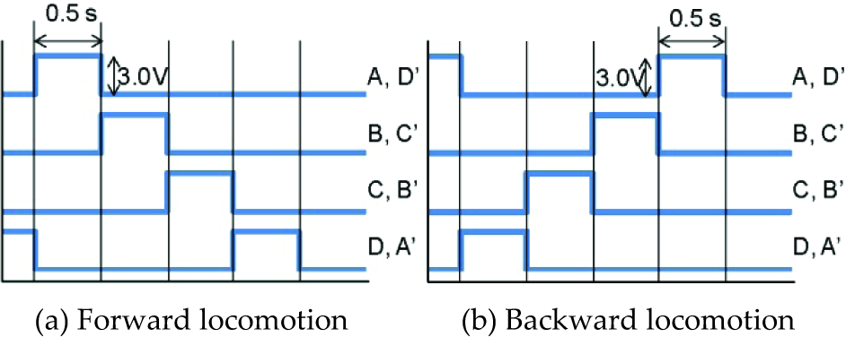
Figure 4 shows the schematic diagrams of the waveform to actuate the constructed biomimetics micro robot. To heat the helical artificial muscle wires, we needed to input the pulse width 0.5 s, pulse period 2 s and pulse amplitude 3 V, as shown in Figure 4. Therefore, the micro robot required 2 s to finish the one cycle locomotion. The pulse waveform of Figure 4 (a) is for forward locomotion, and Figure 4 (b) is for backward locomotion.
Waveform to actuate the biomimetics micro robot
Figure 5 shows the schematic diagram of the locomotion of the biomimetics micro robot. The biomimetics micro robot could move by the rotational actuator and the artificial muscle wire had a characteristic of changing length according to temperature. In the case of heating the wire it shrank and in the case of cooling the wire it extended. In particular, when heating the helical artificial muscle wires from A to D, the MEMS type micro robot would move forward. In contrast, heating the helical artificial muscle wires from D to A, the robot moved backward (A, B, C and D indicate the helical artificial muscle wires of the right side of the robot. A', B', C' and D' indicate the helical artificial muscle wires of the left side of the robot). The locomotion pattern is a 180 degree phase shift on each side to represent the locomotion of the insect. Therefore, small size rotary type actuators, link mechanisms and six legs realized the insect-like switching behaviour.

Schematic diagram of locomotion
3. Active hardware neural network system
It is well-known that locomotion rhythms of living organisms are generated by central pattern generators (CPG). Previously, we proposed the CPG model using P-HNMs [23,24]. The CPG model was a board level circuit using surface-mounted components. The board level circuit was 10 cm square in size, therefore it was impossible to integrate on the biomimetics micro robot system. Proposing HNN is a simplified model of the CPG model for the purpose of further miniaturization.
Figure 6 shows the schematic diagram of the HNN. The four inhibitory neurons are mutually coupled by 12 inhibitory synapses. HNN is a coupled neural networks system which can generate the locomotion rhythms such as those in living organisms. In the case of excitatory mutual coupling of the excitatory neuron by the excitatory synapse, the neural networks systems will in-phase synchronization. On the contrary, for inhibitory mutual coupling of the inhibitory neuron by the inhibitory synapse, the neural networks systems will anti-phase synchronization (for example, see [24]). The output port of the HNN was connected directly to the helical artificial muscle wires by copper wires. The HNN outputs the driving pulses using synchronization phenomena such as biological neural networks. The driving pulses can operate helical artificial muscle wires of the biomimetics micro robot directly. Therefore, the HNN realized the robot control without using any software programs or A/D converters.

Schematic diagram of HNN
3.1 Pulse type hardware neuron models
The P-HNM has the same basic features as biological neurons such as threshold, refractory period, spatio-temporal summation characteristics, and enables the generation of continuous action potentials. The inputs of the synaptic model were output voltage vCn, (1≤n≤3) of the cell body model. The input of the cell body model was output current ism (1≤m≤3) of synaptic model. n was the number of the cell body model and m was the number of inhibitory synaptic model, respectively.
Figure 7 shows the circuit diagram of the inhibitory synaptic model by CMOS. The inhibitory synaptic model has spatio-temporal summation characteristics similar to those of living organisms – spatio-temporal summate the output of three cell body models. The circuit parameters of the synaptic model were as follows: CCS1=CCS2=CCS3=1 pF, MS11–13, MS21–23, MS21–23: W/L=1, MS4,5: W/L=1. The voltage source VDD=5 V.

Circuit diagram of inhibitory synaptic model
Figure 8 shows the circuit diagram of the cell body model by CMOS. The circuit parameters of the cell body model were as follows: CG=39 μF, CM=270 nF, MC1, MC2: W/L=10, MC3: W/L=0.1, MC4: W/L=0.3. The voltage source VA=3.3 V.

Circuit diagram of the cell body model
Figure 9 shows the layout pattern of the HNN. This IC chip was made by On-Semiconductor, HOYA Corporation, and KYOCERA Corporation, The design rule of the IC chip was double metal double poly CMOS 1.2 μm rule. The chip was a square 2.3 mm × 2.3 mm in size. The sizes of the capacitors of the cell body model are too large to implement on the CMOS IC chip. Therefore, the capacitors CG and CM were mounted externally on a bare chip as shown in Figure 10. In Figure 10, three external copper wires were needed to actuate the robot (VDD, VA and GND).

Layout pattern of the HNN

Conceptual diagram of bare chip mounting on biomimetics micro robot
3.1 Locomotion Control by an Active Hardware Neural Network System
Figure 11 shows the example of output waveform of the HNN. It can be seen that the HNN can output the waveform of forward movement and backward movement, as shown in Figure 4. Thus, our HNN is effective at generating the locomotion of the biomimetics micro robot. The waveform was generated by using OrCAD (circuit simulation software), MATLAB Simulink and a waveform generator. In the near future, we will achieve the biomimetics micro robot system such as shown in Figure 10.

Output waveform of the HNN for the biomimetics micro robot
Four signal ports were extracted from the waveform generator and they were connected to the artificial muscle wires directly by copper wires (in [23, 24], four signal ports were extracted from the CPG model and they were connected to the artificial muscle wires directly by copper wires). Ten external copper wires were on the upper part of the robot as shown in Figure 12.

Locomotion of the biomimetics micro robot
Eight copper wires were connected to the artificial muscle wires and two copper wires were connected to the GND wires (see Figure 2(a) and Figure 5). Figure 12 shows the example of locomotion of the silicon micro robot. Hardware neural networks can output the waveform of forward movement and backward movement which is necessary to actuate the silicon micro robot. In particular, our constructed hardware neural networks can control the movements of the silicon micro robot at the simulation level. The locomotion speed was 26.4 mm/min where the step width was 0.88 mm.
4. Biomimetics micro robot system
Figure 13 shows the conceptual diagram of our biomimetics micro robot system. Our biomimetics micro robot system targeted the integration of a mechanical system, an HNN controlling system, a sensory system and a power source system. The mechanical systems consisted of frame parts, small size rotary type actuators and link mechanisms. The locomotion of the biomimetics micro robot was controlled by HNN which is an analogue IC circuit. The sensory system and power source system are under development. Therefore, this paper discussed the integration of mechanical systems and HNN controlling systems. Our target is an advanced package integration of controllers, actuators, sensors and power sources on the silicon frame of a biomimetics micro robot.

Conceptual diagram of biomimetics micro robot system
5. Conclusions
In this paper, we proposed an active hardware neural networks controlled biomimetics micro robot. As a result, we developed the following conclusions.
4.0, 2.7, 2.5 mm, width, length, height size micro robot could be fabricated using MEMS technology.
Hardware neural networks can output the waveform of forward movement and backward movement which is necessary to actuate the biomimetics micro robot. The hardware neural networks output the driving pulses using synchronization phenomena such as biological neural networks. The driving pulses can operate the actuators of the silicon micro robot directly. Therefore, the hardware neural networks realized the robot control without using any software programs or A/D converters. The locomotion speed of the biomimetics micro robot was 26.4 mm/min and the step width was 0.88 mm.
Footnotes
6. Acknowledgments
The fabrication of the biomimetics micro robot was supported by the Research Center for Micro Functional Devices, Nihon University. This study was supported by Nihon University College of Science and Technology Project Research, Nihon University Academic Research grant (total research, “11–002”), JSPS KAKENHI (23760243). We appreciate the support. The VLSI chip in this study was fabricated in the chip fabrication programme of VLSI Design and Education Center (VDEC), the University of Tokyo in collaboration with On-Semiconductor, HOYA Corporation, KYOCERA Corporation and Cadence Design Systems, Inc.