
Abstract
In this paper, we focus on distributed fault detection and isolation (FDI) for a multi-robot system where multiple robots execute a flocking task. Firstly, we propose a fault detection method based on the local-information-exchange and sensor-measurement technologies to cover cases of both perfect communication and imperfect communication. The two detection technologies can be adaptively selected according to the packet loss rate (PLR). Secondly, we design a fault isolation method, considering a situation in which faulty robots still influence the behaviours of other robots. Finally, a complete FDI scheme, based on the proposed detection and isolation methods, is simulated in various scenarios. The results demonstrate that our FDI scheme is effective.
Introduction
Flocking behaviours exist widely in nature in the form of the flocking of birds, the schooling of fish and the swarming of bacteria [1, 2]. Motivated by observations of these flocking behaviours in their environments, multirobot systems are expected to be applied in a wide set of situations, such as exploration, search-and-rescue, unmanned aerial vehicles (UAV), and so on [3]. Recently, the flocking of multi-robot systems has attracted much attention [4, 5]. As the size and complexity of multi-robot systems rapidly increase, the fault detection and isolation (FDI) method in flocking is becoming more and more important. For example, a faulty UAV in a UAV formation can significantly jeopardize the performance of its nearby UAVs, or even destroy the whole formation.
There exist many works on the design of FDI schemes [6–16]. Some of these works concentrate on FDI schemes with a centralized control structure [6–10]. Robust model-based fault diagnosis methods for dynamic systems are proposed in [6], but they focus on fundamental issues, such as basic definitions, residual generation methods and the importance of robustness in model-based fault diagnosis approaches. A Hinf-based structured fault detection and isolation (Hinf-SFDI) method is introduced in [7]. For Hinf-SFDI, all the information is sent to a central FDI unit through wireless channels, which increases the communication burden on the FDI unit. Based on the centralized structure, many FDI approaches that utilize observers have been proposed in [8–10]. However, observers increase the computational burden on robots. Thus, it is not wise to solve the FDI problem with a centralized structure due to the limitations of the communication and computation capabilities of FDI units and robots [11]. Distributed FDI approaches for multi-robot systems have been studied in [12–16]. In [12], by using a bank of decentralized observers, a scheme for fault tolerant distributed network control systems is proposed. In [13], the FDI problem in multi-robot systems is considered as a double integrator dynamics system and each robot uses decentralized observers to estimate system input (e.g., control command signal, noise, interference, etc.). The FDI schemes proposed by [12] and [13] belong to the schemes of state estimation. However, the computational complexity of the state-estimation-based schemes will increase with the increase of the number of robots in a system. The research into distributed FDI schemes is just beginning and there still exist many problems. When performing fault detection, most existing works assume that the communication between robots is always perfect [14–16]. In practice, it is common to find that some robots cannot communicate with other robots. Although in [7] the author has studied an FDI scheme with an imperfect communication channel, it is based on a centralized control structure. When performing fault isolation, the existing works simply remove the robots that present misbehaviour from their connected-graph models. However, these robots still exist in practice and may influence the performance of the system.
In this paper, to tackle these problems, we focus on developing a distributed FDI scheme for the flocking of multi-robot systems. In the proposed scheme, we design a detection method that consists of the local-information-exchange-based detection technology and the sensor-measurement-based detection technology to cover both cases of perfect and imperfect communication, respectively. According to the PLR, the two detection technologies are adaptively selected. By considering a situation in which faulty robots still influence the behaviours of other robots, a fault isolation solution for faulty robots is proposed. Finally, a complete FDI scheme based on the proposed detection and isolation methods is simulated in various scenarios. The results demonstrate that our FDI scheme is effective.
The remainder of this paper is organized as follows. The system model is described in Section 2. The detection and isolation methods are discussed in Section 3 and Section 4, respectively. The simulation results are presented in Section 5 The conclusion is introduced in Section 6
System Model
In this section, we firstly model a multi-robot system as a graph. Then, we introduce the residual generator of the multi-robot system.
Topology of Flocks: Proximity Nets
The topology of a multi-robot system can be regarded as a graph G(V, E), which consists of a set of vertices V = {1, 2, …, n} and edges E ⊆ {(i, j): i, j ∊ V, j ≠ i}. The graph G is undirected, i.e., the edges of satisfying the condition of (i, j) ∊ V ⇔ (j, i) ∊ V.
The adjacency matrix

We consider a group of dynamic robots with the motion equation

where
Let r > 0 denote the communication range between two robots. An open ball with radius r determines the set of the spatial neighbours of robot i, which is denoted by

where ||•|| is the Euclidean norm in ℝ m . A robot with its spatial neighbours is shown in Figure 1. Let d > 0 denote the measured range between two robots, which is twice that of the communication range r, i.e. d = 2r.

A robot and its spatial neighbours
Flocks: A group of robots is called a flock if all the robots are connected over the time interval t ∊ [t0,tf], tf ≥ 0, have the same velocity and keep the lattice or shape.
σ − norm: The non-negative map is called σ − norm, which is used to construct a smooth collective potential of a flock and the spatial adjacency matrix of the proximity net.
The σ − norm of a vector is a map ℝ m → ℝ≥0 that can be defined as

With a parameter ∊ > 0, the map ||z||σ is differentiable everywhere, while ||z|| is not differentiable at z = 0. Thus, ||z||σ will be used in this paper.
According to [17], each robot in the free flocking applies a control input that consists of two terms
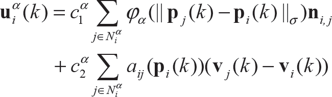

where

Based on the control input of the multi-robot systems, we can generate the residual for the FDI.
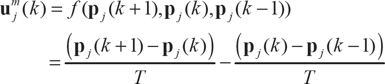
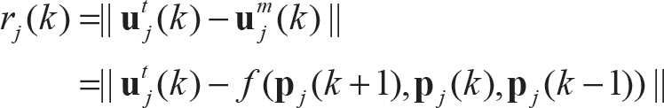
In multi-robot systems, every robot has its own individual FDI system. And the residual of every robot is defined as

where ri(k) is the residual signal,
Since an attempt to evaluate the residual signal over the entire time would usually be unrealistic, the evaluation function in this article is computed as the average energy of the residual signal over a given time interval (k1, kτ)

where k1 denotes the initial evaluation time instant and kτ stands for the evaluation time. The detection logic unit is based on the works proposed in [18].
Thus, the threshold used to detect faults is defined as

Based on equation (10), the occurrence of faults can be detected by comparing Jr(τ) and Jth

By comparing the residual with its threshold, we can obtain the definition of the faulty robots.
Faulty robot: the robot i is faulty if Jr(τ) satisfies the constraint that

When performing fault detection, most existing works assume that the communication between robots is always perfect. In practice, it is a common for some of the robots not to be able to communicate with the other robots. So it is very relevant to research distribute fault detection methods, considering whether communication between robots is perfect or imperfect.
Perfect Communication
If communication between different robots is perfect, we propose a fault detection method, which requires that robot j broadcast its own position information
When robot i receives
The measurement value of
Then, according to equation (8), robot i can generate the residual signal of robot j ∊ Ni(k) using the follow equation
Based on the threshold Jth, robot i can identify whether the robot j ∊ Ni(k) is faulty or not.
If robot i cannot receive the data packet correctly, it means that the communication channel is imperfect. In this case, sensor-measurement-based detection technology is used.
When the communication between the different robots is imperfect, we consider using on-board sensors (e.g., laser scanning rangefinder) to measure the distance dij(k) between two robots and the relative angle β ij (k) of these two robots' direction at the time step k.
For the sensor, we assume that the measurable range of the distance is twice the range of communication. Thus, if the robot i has a neighbour j at the time step k, the robot i can measure all the neighbours of robot j because they are within the communication range of robot j. To generate the residual signal, we need to calculate

and

Then, we calculate
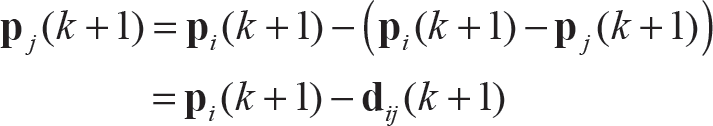
After predicting
The Gaussian Mixture Model (GMM) can be used to approximate any distribution [20]. In this paper, we utilize the GMM to build the distribution of PLR.
Essentially, the GMM is a kind of multidimensional probability density function and can be expressed by a linear combination of the Gaussian density function. Therefore, the distribution of PLR can expressed as follows

where
We utilize the Expectation Maximization (EM) algorithm to estimate the parameter set of GMM [21, 22]. It is an iterative method for finding parameters in statistical models. The EM algorithm involves two steps: the E step and M step. It repeats the E step and M step to obtain the parameter set Θ.
Let
The E step computes the conditional probabilities

The M step updates the parameter set Θ

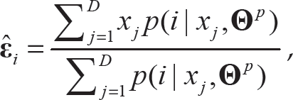

where Θ p is the parameter set acquired from the previous iteration.
According to the GMM and EM algorithm, we can obtain the prior distribution of the PLR. To estimate the PLR, a few probe packets are sent. The details of the estimation process are described as follows.
Consider a scenario where robot A sends packets to robot B. If A sends Dsend packets and B receives Drecv packets during time t, t ∊ {k, k + 1}, we can calculate the PLR of the communication link from robot A to robot B by
We want to estimate unobserved PLR x(k + 1) on the basis of observations x(t). Let p be the sampling distribution of x(t). Assuming that a prior distribution g over x(k + 1) exists, the posterior distribution of x(k + 1) is

The estimated value of x(k + 1) is

The threshold of PLR determines whether the communication is perfect or not and guides robots to select the suitable detection method. We define the threshold of PLR as m. If the estimated value of PLR is larger than the threshold m, it means that the communication is imperfect.
In this section, we propose a fault isolation scheme by considering a situation in which faulty robots still influence the behaviours of other robots.
We define the dangerous distance of a non-faulty robot as rd. We define the security distance between a non-faulty robot and a faulty robot as rs. We assume that the dangerous distance rd is smaller than the communication range r and the sensing distance d, i.e., 0 < rd < r < d. The ball with the faulty robot's position as a spherical centre and rd as the radius is called the dangerous zone. Figure 2 shows how a robot isolates the dangerous zone of a faulty robot. In Figure 2, the vector from the non-faulty robot to the faulty robot is defined as
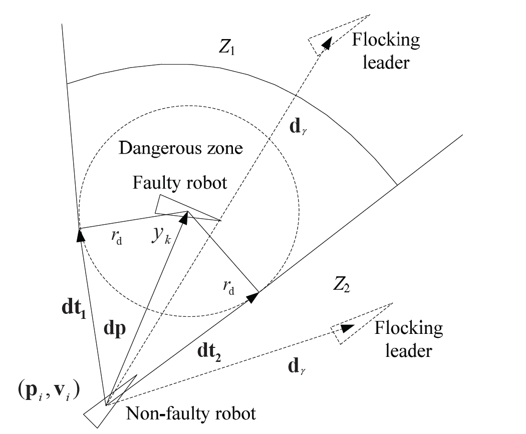
Faulty robot isolation
After a non-faulty robot detects the faulty robot, the non-faulty robot will judge whether the orientation of its velocity is between

If the orientation of the velocity does not satisfy the rule, the non-faulty robot does not need to change its trajectory. The reason is that the faulty robot cannot influence the non-faulty robot in this situation. If the orientation of the velocity satisfies the above rule, then we start to perform the isolation solution. The solution is designed to cover cases whether flocks are formed or not.
If the flocks have not been formed, every robot does not have the same velocity as its neighbours. All the non-faulty robots' final movement goals are the leader's position. As a result, the faulty robot isolation should regard the leader as the reference.
As shown in Figure 2, when the leader's position is in the zone Z1 (i.e., behind the faulty robots) and the non-faulty robot satisfies the following rule

Then, the non-faulty robot i adjusts the orientation of its velocity to the tangent of the dangerous zone to isolate the faulty robot and make the least deviation possible from the leader at the same time. To achieve this, the new velocity of this non-faulty robot can be defined as

Sometimes, the lead robot is in Z2 (i.e., it is not behind the faulty robot) and the non-faulty robot satisfies the rule

In such a case, the faulty robot will not influence the non-faulty robot. The robot i will turn the orientation of its velocity to the leader's orientation and the new velocity of this non-faulty robot is defined as

If flocks have been formed, the non-faulty robot i has the same velocity as all its neighbours. In this case, the non-faulty robot should guarantee the same velocity as all its neighbours as much as it can. It does not need to consider the position of the leader. When the faulty robot is detected by the non-faulty robot, the non-faulty robot i adjusts the orientation of its velocity to the tangent of the dangerous zone. The new velocity of this non-faulty robot is the same as (27).
Experimental Results
In this section, we apply our FDI scheme to the multi-robot system that performs the flocking task. The system has double integrator dynamics. Robots move to flock in the 2D space with the aforementioned control law as depicted in (5)–(7). The initial x and y axes of the robots are randomly generated between [0, 50]. Furthermore, their initial velocity is set to zero. The leader of these robots always moves at a speed of 16m/s in the simulation procedures. Each robot has a communication range of 8.4m, and correspondingly, their measureable distance is 16.8m. When the robots form the flocks, the distance between any two neighbour robots is set to 7m. The dangerous distance is set to 6m. Unless specified, we consider practical conditions in our simulation situation, i.e., that the communication may be perfect or imperfect.
FDI in Multi-robot System
In this subsection, we show the effectiveness of the proposed FDI scheme by observing the flocking of the system. We configure 10 robots in our simulations.
Figure 3 demonstrates a scenario where two faulty robots occur at time 3750ms in the multi-robot system that has formed the flocking. Each curve in this figure shows the velocity of the robot with time. We assume that the communication between the robots is perfect and no FDI scheme is used. We can observe that the velocities of all the robots are not identical anymore after 4000ms, i.e., the flocking has been broken. The reason is that the faulty robots that are not isolated have a bad influence on the behaviours of the other robots in the system.

Velocities of the robots without FDI
Figure 4 demonstrates the velocities of the robots when the faulty robots are detected and isolated by the proposed FDI scheme. In this figure, two faulty robots occur at time 750ms. It can be observed that the robots reach a similar velocity again after a short confusion time caused by the faulty robots, i.e., the multi-robot system forms the flocking again. This phenomenon indicates that the proposed FDI scheme, which isolates the faulty robots, is effective. It is necessary to avoid faulty robots instead of just ignoring them as in the conventional isolation schemes (e.g., the schemes in [7] and [8]).
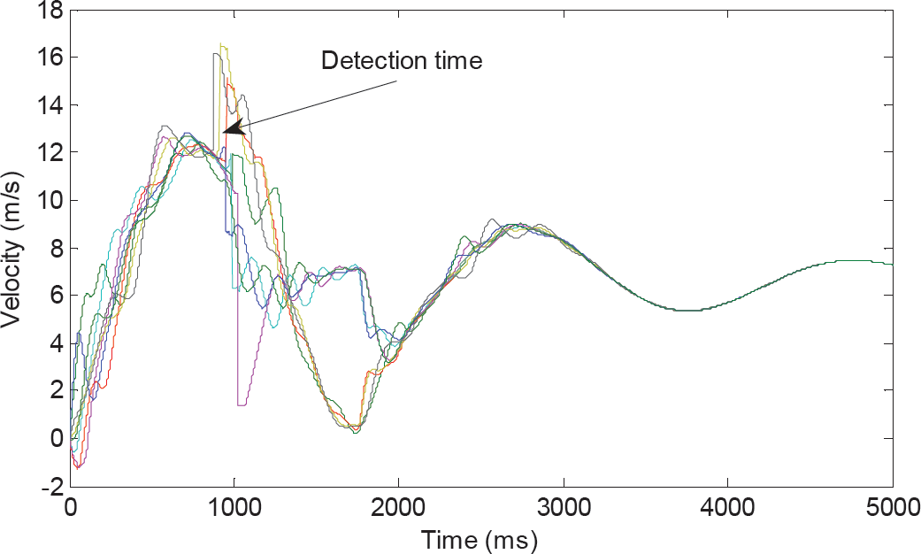
Velocities of the robots with FDI
The benefits of using our FDI scheme for multi-robot systems are investigated in this subsection. We compare our FDI scheme with two typical methods in [7] and [13]. A Hinf-based structured FDI method (Hinf-SFDI) is introduced in [7]. Hinf-SFDI is a centralized FDI architecture. For the method introduced in [13], a scheme based on the unknown input observer (UIO) was used to detect faulty robots. Each robot has one observer corresponding to a neighbour. As in other conventional works, the isolation methods in [7] and [13] simply ignore the faulty robots.
In the simulation, we configure n ∊ {2, ···, 10} robots and one faulty robot. All the robots have the same initial x and y axes, and their initial velocity is set to zero. Each simulation runs 20 times to determine the mean and standard deviation of the time of the FDI.
In Figure 5, we present the time efficiency of the fault detection varying with the number of robots involved in the task of flocking in a multi-robot system. From this figure, we find that the proposed FDI method based on a local information exchange takes less time to implement the fault detection than the other two approaches based on a large number of statistics, the results of which are above. It indicates that the proposed FDI scheme is more efficient than the other two schemes.

Time efficiency vs. the number of robots
Then we configure 10 robots and q ∊ {1, ···, 3} faulty robots. Each simulation will run 50 times to determine the correct rate of fault detection.
Figure 6 shows the correct rate of fault detection varying with the number of faulty robots involved in the task of flocking in a multi-robot system. The correct rate of detection is defined as

Rate of correction detection vs. the number of robots
In this paper, we considered the problem of faulty robots in multi-robot systems with double integrator dynamics. We proposed a distributed FDI scheme to resolve this problem. A detection method based on the local-information-exchange and sensor-measurement technologies was proposed to cover cases of both perfect communication and imperfect communication. Considering the fact that faulty robots still exert a bad influence on the system, we designed an isolation method that allows the non-faulty robots to avoid the faulty robots. The simulation results demonstrate that the application of the proposed FDI scheme is effective.