
Abstract
High-speed legged locomotion pushes the limits of the most challenging problems of design and development of the mechanism, also the control and the perception method. The cheetah is an existence proof of concept of what we imitate for high-speed running, and provides us lots of inspiration on design. In this paper, a new model of a cheetah-like robot is developed using anatomical analysis and design. Inspired by a biological neural mechanism, we propose a novel control method for controlling the muscles' flexion and extension, and simulations demonstrate good biological properties and leg's trajectory. Next, a cheetah robot prototype is designed and assembled with pneumatic muscles, a musculoskeletal structure, an antagonistic muscle arrangement and a J-type cushioning foot. Finally, experiments of the robot legs swing and kick ground tests demonstrate its natural manner and validate the design of the robot. In the future, we will test the bounding behaviour of a real legged system.
1. Introduction
High-speed running is an important topic in current legged robot research, as it places extreme demands on our understanding of mechanical design, control and perception. The construction of a robot that mimics the biomechanics of a real mammal will be followed by a description of the fuzzy nature of the problem; equally, it will help us to better understand the complex interplay between neural control and biomechanics.
Previous work has shown that a robot's overall performance can be improved when abstracted biological principles and devices are incorporated into the control method and mechanical design. Raibert's monopod hopper was the first fast-running robot with prismatic joints [1]. Further, he developed a four-legged system which runs like a spring-loaded inverted pendulum (SLIP) [2] with trotting, pacing and bounding gaits [3], while the SLIP model is recognized as the best template for animal running. Through a Poincare map, dynamic properties were analysed for the legged robot [4]. At McGill, SCOUT II became the first physical robot to achieve a stable gallop considering compliant prismatic legs [5]. Stanford and Ohio State have done a lot of work on improving the performance of articulated limbs [6]. The KOLT quadruped that they designed could gallop at high speed. Using articulated limbs, the motion of the robot can be compared more closely to a biological system [7].
However, these robots are either too rigid or else use linear joints controlled by electric motors. In contrast, an animal's musculoskeletal system comprises a complex and redundant structural morphology with nonlinear materials of viscoelastic muscle-tendon tissues, and it has no sensors or actuators to directly sense and control its joints. Recently, many researchers have followed this line of investigation to better understand the mechanisms underlying animals' locomotory skills in order to apply them to robots [8]. The HRL lab created an innovative cheetah robot hindlimb using the concept of a biarticular muscle, which means that the muscle spans two joints [9]. Garcia with her colleagues developed a horse's leg (HADE) using a hybrid actuator whose performance was likened to a biological muscle [10]. Many other new actuators have been used for new robots [11]. Muscle-like actuators, especially artificial pneumatic muscles, have been paid increasing attention [12]. Keith W. Wait et al. designed a quadrupedal walking robot featuring 12 pneumatically-actuated degrees of freedom [13]. PANTER, prototype for a fast-running quadruped robot with pneumatic muscles, shares the same basic conception of a z-shaped construction with mammalian legs [14]. K.S. Aschenbeck et al. built a robot with pneumatic muscles from which morphometric dimensions were extracted to form a full-scale adult greyhound skeletal geometry [15].
Through evolutionary processes, animal morphologies and nervous systems have mutually adapted themselves in order to achieve efficient sensorimotor integration within the environment [16]. Thus, excellent athletic capability has emerged from the dynamic interactions between the body, the neural system and the environment. The neural system exploits the physics of the body, on the one hand, while on the other hand the body dynamically structures the neural dynamics via sensory stimuli [16]. Thus, a natural-like controller is also an important way to achieve various and adaptive behaviours, especially high-speed running [17].
In this paper, through anatomical and morphological imitation and optimization, a prototype of a cheetah robot is designed toward ultra-high speed. In particular consideration of the joint arrangement, the musculoskeletal structure, antagonistic muscle actuation and foot cushion for the cheetah robot are presented in this paper. Besides these, we seek to find an essential biological control method to generate a more natural motion. Using our knowledge of the biological neural system, we propose a locomotion control method combining the neural mechanism controlling the leg's muscles, a muscle model and traditional position control. Finally, given the bounding simulation of the robot model and the leg-swinging and vertical-hopping experiments of the hindlimb prototype, it demonstrates the validity and feasibility of achieving more natural locomotion and high-speed running.
2. Anatomic design
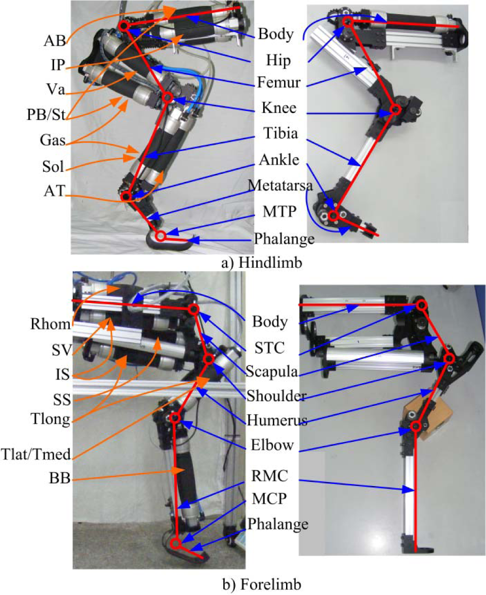
The idea of adapting high-speed movement and fusing as many as biological principles as possible for a running robot was the starting point for our research. In the biological world, the cheetah is undoubtedly the template of our research. It can sprint at 33 m/s in short bursts, covering distances up to 500 m, and it has the ability to accelerate from 0 to over 28 m/s in three seconds. It is pertinent to our high-speed robot design. Our cheetah robot is shown in Figure 1a, which is detailed enough in structure to capture the significant mechanical characteristics of a cheetah running. As shown in Figure 1, our robot has the same joint arrangement as the cheetah. Each leg has four joints, and each joint has one degree of freedom. This arrangement of degrees of freedom is sufficient to adopt a bounding gait, but for the further adoption of a galloping gait, one more degree of freedom (hip abduction) should be added. From proximal to distal, the joints are labelled as the scapula–thoracic cage (STC), the shoulder, the elbow and the metacarpal phalange (MCP) for the forelimb, and the hip, the knee, the ankle and the metatarsal phalange (MTP) for the hindlimb. From proximal to distal, the leg segments are labelled as the scapula, the humerus, the radius-metacarpals (RMC) and the phalange for the forelimb, and the femur, the tibia, the metatarsals and the phalange for the hindlimb.

The structure of the robot and the cheetah
We built a musculoskeletal structure following that of the cheetah. The three proximal articulations for each limb were actuated by pneumatic muscles. The distal ones, the MTP and the MCP are compliant joints with a J-type cushioning foot. These features would be discussed in the following sections. For the robot model, we redefined the segments and the joints of the forelimb according to the running function. We took the scapula as a part of forelimb, eliminated the function of the wrist joint, and defined a new articulation between the scapula and the thoracic cage, namely the STC. A lot of recent studies have demonstrated the new propulsive function of the scapula, which has led to a profound restructuring of the shoulder and forelimb [18,19]. Incidentally, a comparative simulation was also performed to test the scapula's function and our hypothesis regarding the forelimb's structure. We built two models - one was the same as our robot while the other did not have scapula segments - and added the wrist joint which is the normal structure as the previous robots. Under the same control algorithm, the two models exhibited different running abilities. The model with the scapula ran 55% faster with a 15% longer stride length than the model without the scapula, as shown in Figure 2; in addition, the stride frequency rose from 1.5 Hz to 2 Hz. The scapula expands the swinging range of the forelimb, which could help it in reaching a further touchdown point. Besides, the simulations also show that the wrist joint is stiff and almost unbowed. Actually, the wrist is very useful for avoiding obstacles and snatching food, but for high-speed running it is useless. Thus, the results of the test verified the propulsive function of the scapula segment and the unnecessary use of the wrist joint. Under this forelimb arrangement, it has an analogous structure to the hindlimb. This means the scapula is equivalent to the femur, the humerus to the lower leg and the lower arm to the hind foot.

The forelimb movements of two models
The structural parameters of the robot are listed in Table 1, and we make a comparison between the robot and the anatomical measurements of cheetah body-structures [20–22]. The scaling from the anatomical model to the robot model is 1:1. Considering the physical implementation and the actuator's installation, some of the segments' sizes are adjusted, but the adjustments are all less than 1%. The mechanical body of the robot weighed 52 kg, while with the power system the robot weighed approximately 70 kg. A small weight increase will not influence the robot's movement properties or the mimetism of the cheetah.
The comparison of the structural parameters. The values are means ± standard error.

3. Bio-inspired control
The quadruped employed an evolutionary nervous system to dominate the coordinated motion of the muscle groups. As the nervous system is concerned with locomotion, we focused on the neural mechanism controlling the muscles and the activation relationship among the muscle groups. As shown in Figure 3, except the distal compliant articulation, the other three proximal joints are actuated by muscles for each limb. We considered seven muscles in the model of the hindlimb and seven in that of the forelimb. Among these muscles, 10 act over single joints: IP (iliopsoas, hip flexion), AB (anterior biceps, hip extension), Va (vastus, knee extension), TA (tibialis anterior, ankle flexion) and Sol (soleus, ankle extension) for the hindlimb, Rhom (rhomboideus, STC extension), SV (serratus ventralis, STC flexion), SS (supraspinatus, shoulder extension), BB (biceps brachii, elbow flexion) and Tlat/Tmed (triceps brachii-lateral and brachii–medial, elbow extension) for the forelimb. There are four biarticular muscles: PB/St (posterior biceps and semitendinosus, hip extension and knee flexion) and Gas (gastrocnemius, knee flexion and ankle extension) for the hindlimb, and IS (infraspinatus, STC flexion and shoulder flexion) and Tlong (triceps brachii-long, shoulder flexion and elbow extension) for the forelimb.

Muscle configuration. The abbreviations here are defined in the text. The red lines show the connections of the muscles
3.1 The muscle model
Our robot is driven by muscle-like actuators and built as a musculoskeletal structure. Thus, for the controller, we first considered building a muscle model. As a large feline, the cheetah has muscle properties similar to those of cats. Hence, in this paper, the simulations of the muscles were based on a model of a cat's soleus muscle [23]. The muscle force F is expressed as:

The force-length relation is:


The passive force is:

Parameters of the muscle model. These parameters are all derived from the research on the cat soleus muscle in [23], (except for the first three: a, x and v).

3.2 Neural mechanism control
The robot was chosen to run at bounding gait, which is a common form of (and the simplest type of) quadrupedal high-speed running. As shown in Figure 4, based on a finite state machine we separated the movements of the legs into four steps: swing, touchdown, stance and lift-off. Further, these four steps could be divided into two phases: a stance and a flight phase. During the flight phase, the primary task is to avoid the ground and to select a feasible touchdown angle. This means that the flight phase is a kinematic process. Conversely, the stance phase is a typical dynamic process, during which the muscles need exert significant power to hold the body and to drive the process of fast running. Therefore, in order to reduce the complexity of the control system and improve its capacity for generalization, a method combining a neural mechanism and a PD controller under a finite state machine is proposed, as shown in Figure 4. We used a PD controller during the flight phase, which is easy to realize in engineering, and we proposed a bio-inspired method controlling the activation of the leg's muscles during the stance phase (which is under the biological neural mechanism). The neural mechanism used in our simulation was incorporated by a subset of the known features of the biological system controlling the cat's legs [24]. Our aim was to construct a viable and understandable control method to solve the kinematic redundancy problem of segmented legs and to produce stable running. Thus, it does not need incorporate every aspect of the biological properties into the controller. The controller removed the direct coupling between the forelimb and the hindlimb. It could automatically generate the robot bounding gait via interaction with the multi-body dynamic system complying with the finite-state machine.

Schematic of the control system
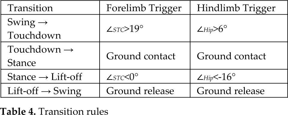
The control method has been elaborated in other papers [25, 26], so we provide here just a summary. As shown in Figure 4, we take the hindlimb as an example to explain the control strategies, noting that the forelimb and the hindlimb are analogous [18]. In Figure 4, the red lines represent the muscles acting according to the muscle model, the grey lines represent the inactive muscles, and the blue lines indicate that the muscles are under position control. During flight phase, we employed a traditional PD controller. However, due to the antagonistic muscles' actuation, we distributed the input variables for each muscle via the leg's geometry calculation [27]. The legs draw back to the body during the swing step and extend to prepare for ground touchdown during the touchdown step. During the stance phase, the neural mechanism control system becomes effective via controlling the muscles' activations. Each muscle's activation allows for a particular relationship with the joint angle, joint angular velocity and muscle force. These relationships are obtained from previous studies on the neural mechanisms regulating running and walking in mammals, such as the kinematics of leg movements, the patterns of neural activity among leg muscles, and the neural mechanisms controlling stepping. Changing the parameters of the neural control system would achieve different robotic locomotion. This method has been discussed in previous papers [25, 28]. For this paper, only feasible parameters for activating the relationships and step transition rules were chosen, as shown in Table 3 and Table 4, all of which are used in the simulation in the next section.
Parameters of the neural control system

Transition rules
3.3 Simulation results
The simulation program was developed as the schematic shown in Figure 4 in the environment of MATLAB/Simulink®. The prototype of the simulation is same as in Figure 1a, which was built using the ADAMS™ software. Utilizing the parameters in Table 3 and Table 4, the robot model runs from rest with a bounding gait. As shown in Figure 5, the robot accelerated from 0 to 1.5 m/s in just one stride cycle. After 0.6 s, the bio-inspired controller achieved stable running and could reach 2.7 m/s as the highest speed. The dimensionless speed is û = √v2 / gl ≈ 1, which is a measure of speed independent of different animal/robot sizes [29]. This speed lies between the preferred speed for trot (û = 0.5) and gallop (û = 2.25) [22], which is precisely the bounding-gait range. The joint movements and the pattern of activation of the muscle Gas were plotted. As shown in Figure 5e, the activation of the muscle was turned on during the stance phase (white area), and during the flight phase (shadow area), and the neural control was deactivated. The simulation results verify the feasibility and validity of realizing the fast running and high acceleration of a robot by employing the bio-inspired control method of the biological mechanism.

The bounding gait. The red dashed-lines show the variations in the forelimb's joint angles and the blue lines for the hindlimb.
4. Biomimetic design
The real model of the robot is shown in Figure 1, which has a musculoskeletal structure following that of a cheetah. The key design goal of this robot has been to create a multi-articulated legged robot that could perform high-speed running the same as a cheetah and exhibit natural locomotion characteristics. This is a comprehensive task that not only involves bio-inspired control but is also concerned with biomimetic mechanical design.
4.1 Joint actuation
As is known, the mammalian articulation is actuated by a pair of antagonistic muscles and, as noted above, our robot is also equipped antagonistic muscle-like actuators as in the simulation model. As shown in Figure 6, the musculoskeletal-type is applied here to actuate joint movement. The flexor provides the driving force and the extensor supplies the antagonistic force. Through the moment arm, the linear forces of the muscle can be converted to rotational joint torque, which acts to resist external forces and move the leg. We can obtain the relationship of the parameters of the muscles and the joints through the calculation of the leg's geometry:
The articulated musculoskeletal type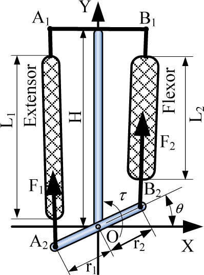


We chose the artificial pneumatic muscle Festo® Fluidic Muscle DMSP as the actuator to construct the antagonistic joint actuation - it displays a strong resemblance to biological muscle with respect to the contraction ratio, the power weight ratio, stress, and stiffness variation. The output properties of the pneumatic muscle are like the upper part of Figure 7a, the grey area encircled by the blue line. It can only provide pulling force. Thus, for the articulated musculoskeletal-type arrangement, the action effect on the joint is just like in Figure 7a, putting the characteristic's curves of the two muscles inverted. The purple line represents the joint force profile. Through (5) and (6), the muscles' force/length properties can be transformed into the joint torque/angle profile. There are several parameters influencing the joint torque/angle profile, such as the number of muscles placed on one side (N), the initial contraction of the muscles (ε0), the maximum length of the muscles (Lmax), the joint moment arm (r), and the length of the ‘bone’ (H). Hence, taking the hindlimb as an example, the joints' torque/angle trajectories obtained from the running cycles' simulation in the above section were plotted as shown in Figure 7b, 7c and 7d (the blue points). In order to determine a reasonable arrangement of the pneumatic muscles for each joint, the boundary of the joints' output profiles must surround the joint working diagram as shown in Figure 7, where the blue line represents the flexor and the red line the extensor. Based on the data-matching, we chose the Festo® Fluidic Muscle DMSP-40 series as the muscle-like actuators and adjusted the parameters for each joint of the fore and hindlimbs so that the joints' working points were encircled by the antagonistic muscles' output profile. The final joints' parameters are listed in Table 5.

The muscles' angle-torque diagram and joint requirements for the hindlimb
The muscles' arrangement. Mus., Ext. and Fle. denote the muscle, extensor and flexor.

Considering the physical implementation, the number and the arrangement of actuators are detailed in Table 5. The muscles are placed like a pair of antagonistic muscles - the flexor and the extensor - as shown in Figure 6. Thus, the functions of the muscles in the neural control method need to be reassigned and redefined for the robot prototype. As with the orange arrows shown in Figure 8 and listed in Table 5, the biarticular effects of PB/St and Gas are reassigned to the hip extensor, the knee flexor and the ankle extensor, and the muscles IS and Tlong are reassigned to the STC flexor, the shoulder flexor and the elbow extensor. Thus, the controlling signals of the muscles' activations generated by the neural control system were assigned to correlated pneumatic muscles in order to generate the same muscular effect as in the simulation. On the other hand, for realizing high performance, the actuators need to provide sufficient power. Hence, we placed some artificial pneumatic muscles in parallel as one so as to enhance performance, such that it could satisfy the joint requirements shown in Figure 7. Table 5 presents the number (N) of parallel muscles. For the hindlimb, the hip and ankle were configured asymmetrically, and the knee were placed the maximum muscles as the thigh is the most muscular segment. For the forelimb, the scapula is the most muscular segment. Actually, asymmetric arrangements are popular in biological systems. For example, the vastus (Va) has three parts (the vastus lateralis, vastus medialis and vastus intermedius) in a real cheetah hindlimb. In the robot system, we use two artificial pneumatic muscles in parallel connection as the vastus muscle. For physical implementation and the reduction of the mass and inertia of the leg, AB and IP are placed along the torso.
The robot prototype
On the distal leg, we designed a J-type cushioning foot to absorb the impact force when landing. As shown in Figure 9, it has similar functions and structures to the animal's foot. The cushioning foot was made of spring steel using bending techniques. The integral-forming foot could be seen as three functional parts: a toe, which has an arc-shape to contact the ground smoothly and continuously; a phalange, which is a steel plate; and a heel, which is the main elastic deformation region with a central hollowed-out structure. As shown in Figure 9, the J-type cushioning foot has a virtual axis O, around which the footplate can bend from position A to B at around 50°.
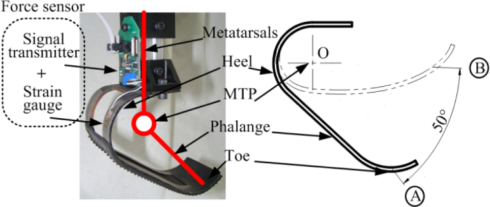
The spring-like foot
The stiffness according to the virtual axis O is similar to the simulation model - about 140 Nm/°. Under the toe and phalange parts, a rubber shoe-sole is stuck on for shock absorption.
4.2 Control system and sensors
As shown in Figure 10, the control system for one leg has a master-slave structure. The leg controller is the host, which generates the running pattern and sends the step transition command to the joint controllers. The neural mechanism control method runs in the joint controller to control the muscles' activation. The dsPIC - a MCU with a DSP engine - was adopted as the processor for the control system (which completes controlling operation) and the signal collecting and processing.
On each joint, we equipped a miniature absolute encoder (SCANCON® SCH24AB) to obtain the joint angular signal and to construct a position feedback control. In order to detect the touchdown event, a strain-type force sensor was equipped on the spring-like foot, as shown in Figure 9. The resistance strain gauge was pasted up on the lateral surface of heel to measure the deformation. Through the calculation of the leg's kinetics, we can obtain the ground reaction force. We designed a signal transmitter to amplify and convert the analogue signal into a digital signal with a sampling rate of 200 Hz. It contains a bridge circuit and an instrumentation amplifier to amplify the analogue signal, and it utilizes a MCU (Atmega16) to process the sensor signal and transmit it to the leg controller as a SSI communications protocol.
The pneumatic muscle was driven by a proportional pressure regulator (FESTO® VPPM), as shown in Figure 10. The air source supplied to the regulator was 8 bar, and the output was varied between 0~6 bar, conforming to the control command. The power source for the robot system is currently off-board - in future, the cheetah robot will have an on-board power source consisting of a lithium battery and a high-pressure carbon-dioxide ice tank.

Control system and sensors
5. Experiments
The previously-described neural mechanism controller was implemented on the pneumatic musculoskeletal robot prototype. In order to test the performance of the cheetah robot, we programmed two experiment schemes. One was for leg-swinging, to test the leg trajectory generation. The other was for vertical hopping, which can be considered to be the basic running motion and is an effective means of testing the leg's dynamical performance.
5.1 Leg-swinging control
Leg-swinging was carried out with the robot system with the aim of demonstrating the natural motion achieved with the proposed controller. The robot was fixed on a falsework to lift the leg up, away from the ground. Thus, the properties of the angular kinematics and position control could be demonstrated. Figure 11 shows the locomotion cycle and the joints' trajectories, programmed employing the proposed control method. In comparison with the simulation results in Figure 5, the profiles of the angular variations of the joints are very similar and have the same trend and phase relation. Note that the aim of this experiment was to test the ability of the control method to generate natural movement and not to determine the maximum possible speed. Therefore, a low angular speed of about 100% was set for the swinging of the legs. This test shows the validity of our position control method during the flight phase.

Sequence of the robot legs' movement cycle
5.2 Vertical hopping
Vertical hopping can be seen as the foundation of running motion, in particular it can exhibit the overall dynamic characteristics during the stance phase. Furthermore, the crucial factor in motion generation is the ground reaction force. The hindlimb plays the main role in running. Thus, we placed the hindlimb on a falsework which was unrestricted in the vertical direction. Utilizing the force sensor on the foot, the vertical force during hopping was obtained and plotted in Figure 12a. The blue line is the mean value, with a maximum and minimum boundary (red dashed-line). In comparison with the simulation (Figure 12b) and biological results (Figure 12c) [30], they have a similar shape for the vertical force profiles. It can be seen that the vertical force profile of each limb is a parabolic curve with an initial spike. Because the hindlimb prototype was engaged in vertical hopping, the fore-aft force in the experiment was ignored. Meanwhile, the fore-aft forces in the simulation and biological results are effective and change sign during the stance. The net fore-aft impulse for the hindlimb accelerated the body. It is worth noting that the hindlimb prototype did achieve around 1.523 times the leg's weight. It reaches the animal's running level, and is similar to the simulation and biological results. There is only a small difference in the initial spikes. This is because the initial spike is related to the foot-ground stiffness and damping - the difference most likely owes to the difference in the ground-impact properties for each other. The similar maximum ground reaction force shows that the neural mechanism control method is feasible during the stance phase.

Comparison of the ground reaction forces: a) the vertical ground reaction force of the robot hindlimb during jumping, b) the simulation results, and c) the forces presented by Walter and Carrier for dogs [30]
The above two experiments verify the validity of controlling the articulated leg using the proposed bio-inspired control method of the neural mechanism in controlling the leg muscles and effecting position control. From another point of view, the experiment also demonstrates the feasibility of the mechanical structure and the actuator arrangement.
6. Conclusion
In this paper, we designed a robot with similar morphological and anatomical characteristics to the cheetah. Utilizing the muscle-like actuator, we proposed a bio-inspired control method under the biological mechanism to control the leg's muscles. Through the simulation, the control strategy exhibited three features: 1) the incorporation of more biological knowledge in the controller, 2) the removal of the direct coupling between the controllers for the forelimbs and hindlimbs, and 3) the automatic generation of the robot bounding rhythmicity via interaction in the multi-body dynamic system. The simulation of the robot model shows that the robot could achieve 2.7 m/s as a dimensionless speed û = 1, which is faster than most quadruped robots [10], and it exhibited good acceleration. Next, a prototype of the robot was assembled with pneumatic muscles, a musculoskeletal structure, an antagonistic muscles arrangement and a J-type cushioning foot. Finally, experiments considering leg-swinging and vertical hopping demonstrated the naturalness of the prototype and validated the proposed control method. From another point of view, the experiment also showed the feasibility of the mechanical structure and the actuator arrangement.
In the future, we will test the bounding behaviour of the quadruped system. Furthermore, the present model of the cheetah robot did not consider the function of the spine, which is important for high-speed running. Thus, we will add the spinal segment, the head-neck segment and the tail segment step-by-step. On the other hand, research into the galloping gait is another area for improving running performance. We will extend our control method from a symmetrical gait (bounding) to an asymmetrical gait (galloping) in the future.
Footnotes
7. Acknowledgments
This paper was supported by the National Hi-tech Research and Development Programme of China (863 Programme, Grant No. 2011AA0403837002), National Natural Science Foundation of China (No. 61375097, No. 61175107).