
Abstract
Playing the game of Ping-Pong is a challenge to human abilities since it requires developing skills, such as fast reaction capabilities, precision of movement and high speed mental responses. These processes include the utilization of seven DOF of the human arm, and translational movements through the legs, torso, and other extremities of the body, which are used for developing different game strategies or simply imposing movements that affect the ball such as spinning movements. Computationally, Ping-Pong requires a huge quantity of joints and visual information to be processed and analysed, something which really represents a challenge for a robot. In addition, in order for a robot to develop the task mechanically, it requires a large and dexterous workspace, and good dynamic capacities. Although there are commercial robots that are able to play Ping-Pong, the game is still an open task, where there are problems to be solved and simplified. All robotic Ping-Pong players cited in the bibliography used at least four DOF to hit the ball. In this paper, a spherical bat mounted on a 3-DOF parallel robot is proposed. The spherical bat is used to drive the trajectory of a Ping-Pong ball.
1. Introduction
Ping Pong or table tennis was invented in England in the 19th century as an alternative to tennis and a solution for bad climatic conditions. Playing table tennis is a difficult task that requires fast movements, accurate control and adaptation to task parameters. Although human beings see and move more slowly than most robotic systems, they perform significantly better than all table tennis robots. In a professional game, players can move up to 10 m/s. and the ball can reach speeds of up to 55.6 m/s. The time during which the ball is in contact with the bat is about 3 ms. The average time that the player needs to react and hit the ball is about 250 ms. Additionally, the visual reaction time of professional players is about 180 ms, while their audio reaction time is about 140 ms. That is the reason why the majority of the players use their sense of hearing to predict the direction of the ball. Among others, it is also why it makes Ping-Pong an interesting challenge for robotics. It is a broad field to study.
The main interest in table tennis for robotics started in the early eighties with a robot Ping-Pong competition that wound down around the late eighties and early nineties. However, due to the complexity of the task and unsolved problems, several groups have continued this line of research until today. In 1987, Andersson [1–4] presented a Ping Pong player. In that work, Andersson used a PUMA 260 and a vision system with four cameras fixed on the workspace, where each camera was able to acquire 256 × 240 pixels images up to 60 FPS. The precision achieved was about 10 mm. The cameras, strategically located, were fixed in two pairs, dividing the workspace into two parts. In 1987, Toshiba Corporation (Energy and Mechanical Research Laboratory) presented a 7-DOF robotic player [5], which was directly driven by DC motors with laser encoders that were able to acquire 106 pulses per revolution. The system locates the ball using stereovision. While the groups mentioned above were involved in designing prototypes, other groups were oriented to incorporate greater intelligence into the systems, such as the Department of Instrument & Control Engineering of the Hosei University, Japan [6], where an algorithm to play against human beings or other robots was developed. The controller was based on fuzzy logic. It was integrated with 25 rules per variable to control (in total three variables). The first variable to control was the position in which the robot hit the ball, the second was the angle at which it hit the ball and the third was the target angle. In 1990, in [7], a 6-DOF low inertia robot arm was proposed. In that work, the main objective was to achieve a fast dynamic performance. The robot was tendon-driven so as to obtain low inertia links. The visual system was made up of a CCD camera pair, which was able to acquire images of 422 × 579 pixels and up to 50 FPS. In 1994, in [8], the authors suggested using a simply designed robot (two DOF cylindrical robot and a two DOF wrist) and a Transputer (a name given by INMOS Company) -based control for the robotic player. The visual system was made up of two fixed cameras, with their fields of view placed parallel to each other. More recently, in a 15-year project (1991–2006), at Miyazaki laboratory, a robotic Ping-Pong player was designed [9–11], built and tested [12]. The robot system was basically a 4-DOF decoupled robot, a 2-DOF Cartesian coordinate robot and a 2-DOF wrist. This system always hit the ball at the desired height (200mm) and the bat was located in the desired position with its desired oriented position on the table. The visual system was a Quick MAG System 3 (OKK Inc.), which was a stereoscopic system used to obtain the 3D position of an object. The images were RGB, 640 × 416 pixels with a sample frequency of 60 FPS. In 2003, in [13], a low cost Ping-Pong player was presented. This system used a single fixed camera able to acquire images of 384 × 288 pixels. The mechanical system came with five DOF. It was provided with two bats that were used to cover a bigger workspace. In 2005, in [14], an interesting image analysis technique called Displaced Frame Difference (DFD) was applied. It took into account consecutive image frames to detect objects in movement. The approach used a CCD (640 × 480 pixels) calibrated camera, which was driven by a USB communication port that obtained up to 15.15 FPS. Additionally, the system used a commercial robotic arm from the Mitsubishi company, model RV-2AJ, and five DOF.
Using robots in the real world has always been a challenge and, even nowadays, it requires that the robot have a strong dynamic optimization and that the elements of the system be correctly integrated. In 2008, in [15], a similar system to the one developed at Miyazaki Laboratory [9] was used. Nevertheless, from a visual analysis point of view, this approach was, at the time, a novelty due to the proposed approach of using the Neuronal Network in RGB spaces. The system used two fixed Blaster 310A cameras and acquired images up to 60 FPS, of 640 × 480 pixels. The position of the ball was located in polar coordinates by a colour recognition technique. The authors showed that the system could be fully integrated to work in real time. In other topics, detecting the position of the ball was already an issue and had been studied independently. In 2009, in [16], a method for fast Ping Pong ball detection using two consecutive image frames was proposed. This work used two calibrated cameras of up to 100 FPS. Image processing was basically divided into two parts: firstly, two consecutive frames were rested in order to detect the movement of the ball and, secondly, the method definitely obtained the position of the ball. Additionally, at the first instance, the full image was analysed. Once the position of the ball was detected in future frames, a region of interest was analysed by using the previous position of the ball. Other studies have been oriented towards studying the interactions that occur when a human being plays Ping-Pong, such as in [17, 18], where a Biomimetic robotic system is proposed. The main objective of the system, using a seven DOF BARRET WAM robot arm, was to imitate the movements of a human Ping-Pong player. The robot arm has a low inertia mechanical system and its visual system acquires up to 60 FPS. In [19], a system is described based on the one designed by Acosta [13], which obtains speeds of up to 5 m/s in the ball tracking by using a monocular system. In [20], a stereo system is shown with 640 × 480 pixels cameras, which was designed so that the arm of a humanoid robot detects the ball at speeds close to 15 m/s. In [21], an interesting contribution for an arm of a 7-DOF humanoid with a stereo vision system operating at 150 FPS was presented. Furthermore, worthy of mention is the contribution in [22], which provides a detailed analysis of the trajectory of the ball with various effects, using the least squares method.
Since Ping-Pong has always been an interesting topic in robotics, Andersson observed that catching or batting a ball would be a simpler task for the system than he had designed. Since then, several applications related to catching and batting tasks have been developed. Some of the most well-known works were developed at the Ishikawa laboratory. In [23], a spherical robot was suggested for batting a ball. The robot and a grip were designed to achieve accelerations of up to 100 G, where the grip and the robot used magnets and springs so as to achieve such accelerations. In the related experiments, the robot reached up to 91G and caught the ball in 25 ms. In that work, the visual system was a stereoscopic pair designed in the laboratory [24] that was able to acquire and process up to 1000 FPS (parallel acquiring and processing [25]). In 2004, a batting robot using the same visual system and a four DOF serial robot were designed at the Ishikawa laboratory. The robot was actuated by direct drives (no gear reduction) with its end effector being able to move up to 6 m/s and 58 m/s2. This application showed notable advancement. However, the direction of the trajectory of the ball had not been corrected in this work. However, in 2006, in [26], the direction of the ball was corrected by using a flat bat. In that work, the robot was able to score in a fixed basket. In 2009, in a more recent work at the Ishikawa laboratory, a robot that could perform juggling tasks was proposed. In that system, the robot combined tactile sensors (consisting of two outer electrically conductive films that were located in three fingers) with the visual system applied in the above works [27]. As previously mentioned, several works have complemented visual information by using different sources and modelling techniques that could be extremely complex. For example, full models were developed for complex scenes [28] or simple models that represented a reduced number of parameters [29].
Most of the research studies mentioned above are focused on how a ball is hit in order for it to follow a desired direction. Nowadays, considering what we know and the literature available, this task has been solved particularly well by Miyazaki laboratory (although the system has not been able to beat an expert human player). It should be mentioned that there are types of robots that have not been used in order to solve this task, such as parallel robots [30]. However, thanks to the position of the actuators, parallel robots are ideal for achieving high speeds and acceleration at the end of the robot. In contrast to previous works that use a fixed stereoscopic pair and at least four DOF in the robotic system, this paper proposes a three DOF parallel robot and a hand camera for this task. As can be observed in previous works, three translational degrees of freedom have not been sufficient enough to impose a desired position using a flat bat. Therefore, a spherical bat has been designed. By hitting a desired point on the surface of the bat, it is possible to impose a direction on the ball after it is hit. This article shows two algorithms that have been designed and tested in order to drive the spherical bat. Due to the complexity of the environment in a real Ping-Pong game and the need to obtain repetitive data in order to compare the bat-driving algorithms, it should be considered that the environment is strongly simplified, the ball is hung using a thread, and the robot hits the ball against a flat wall. Additionally, although this part has not been studied in this article, the robot is a single camera in hand architecture. The robot is not able to see the ball while it is being hit. Thus, the visual system has to deal with occlusions. The position and velocity of the ball should be precisely estimated. It has to be taken into account that a camera located on the hand of a parallel robot has never been proposed for Ping-Pong Robots. It is an open field to explore.
This article is organized as follows: the first section is the introduction. Section two presents a description of the task and the system. The three specific contributions of this article are also explained in detail. They complement the overall contribution for the development of a RoboTenis system with a spherical bat. Section three describes the strategy of striking the ball. Section four presents two novel corrections for the precise determination of the ball in space. Finally, section five presents an algorithm to determine the position of the ball at impact. The article ends with the conclusions.
2. System description
The RoboTenis system was created to study and design visual servoing controllers and to carry out object tracking in dynamic environments. Several algorithms have been designed in order for the robot to be able to hit a Ping-Pong ball hanging from a thread.
The mechanical structure of the RoboTenis system was inspired by the DELTA robot [31, 32]. A robot of three degrees of freedom that is translational. The RoboTenis platform (Figure 1) basically consists of a parallel robot, and a visual system for acquisition and analysis. The maximum end effector speed of the parallel robot is 6 m/s and its maximum acceleration is 58 m/s2. The visual system of the platform RoboTenis [33] is made up of a 0.05 kg camera that is located at the end effector (figure 1, figure 2) and a frame grabber (SONY XCHR50 and Matrox Meteor 2-MC/4, respectively). The motion system is composed of three AC brushless servomotors, Ac drivers (Unidrive), and planetary gearboxes. The joint controller is implemented on a DS1103 card (software implemented in ANSI C). The camera was calibrated following the method proposed by Zhan [34].

System RoboTenis
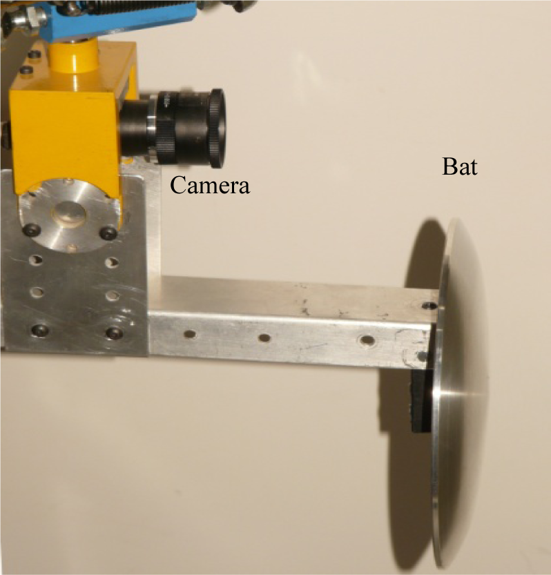
Camera and bat
Hitting a ball with a 3-DOF parallel translational robot is a challenge, due to the impossibility of orientating the strike properly. As a solution, a novel semi-spherical bat has been designed (figure 2). This allows for the orientating of the direction of the ball. The degrees of freedom of the robot are reduced by designing algorithms to set the position of the bat upon hitting the ball. This represents an additional requirement to the system in two key aspects. On the one hand, a more accurate detection of the position of the ball is required. On the other hand, visual control algorithms with better static and dynamic performance have to be used. The bat was designed under the assumption that the trajectories of the ball would be corrected in each progressive strike, so a gentle curvature radius of 400 mm was chosen. The total area of the bat is 268 mm2.
3. Strategy for striking the ball
The aim of the application described is for the robot to be able to indefinitely strike a Ping-Pong ball hanging from a thread bouncing against a flat wall. It is essential to control it in order to keep the ball inside the robot workspace. As a strategy, the ball is set to bounce against the wall at a predetermined point (centred with respect to the workspace of the robot) and to hit it at an angle close to 90 degrees. The robot with three translational degrees of freedom can carry out its desired task thanks to the spherically designed bat and its position.
The strategy designed for striking the ball uses three virtual planes that are perpendicular to the Z axis of the camera (the Z axis of the camera coincides with the X axis of the robot coordinate system) that delimit three zones of activity (figure 3). The subscript c stands for the coordinate system tied to the optical camera centre, while the subscript s stands for the coordinate system of the hitting that is located at the end of the robot. The relationship between the two is determined by a kinematic calibration. When the ball is farther away from plane 1, the vision system at the end of the robot estimates the position and velocity of the ball. Meanwhile, the robot moves on plane 3 as it plans the moment to strike and the position, based on the estimated path. Considering the layout of the camera and the bat when the ball approaches, the vision system stops the vision of the ball, so that, from that moment on, the information previously estimated is used. Moving the robot on plane 3, this point occurs when the ball traverses plane 1. Plane 2 defines the plane in which the robot will hit the ball if the trajectory of the ball allows it to strike inside the robot's workspace. If the system considers when the trajectory of the ball crosses plane 2, it will be out of the workspace and it will slightly alter the position of the plane. It should be noted that the distance between plane 2 and plane 3 fixes the impulse received by the ball at impact.

Strategy for striking the ball
In the tests performed, plane 3 is located 40 mm from the origin centre, plane 2 is 180 mm from plane 3 and plane 1 is 380 mm from plane 3. The wall, against which the ball bounces, is parallel to the YZ plane of the robot (XY of the camera) and it is set at 1120 mm from plane 3. It should be noted that the bat is located at a distance of 160 mm from the end of the robot. Therefore, the actual hit occurs when the ball is 340 mm (180 +160) from plane 3. The robot's speed at the moment it strikes is close to 2 m/s, whereas the estimated maximum speed of the ball was 3.7 m/s.
In order to strike the ball, the robot has to perform two types of motion: a tracking motion on plane 3 and an impulse motion for the strike when the robot moves from plane 3 to plane 2. For this purpose, a control structure with two control loops has been designed. This consists of a visual outer loop that runs every 8.33 ms, a predictive algorithm and an articulating inner loop with a PD controller that runs every 0.5 ms. The control achieves a high dynamic performance. The algorithms and their stability are described in more detail in [33] or [35]. The vision system determines the spatial position of the ball. It is worth highlighting that, due to the acquisition and processing of images, there is a delay between the visual information supplied and the actual position of the robot; a delay that is necessary to use the control system in a proper operation. This delay is estimated at being about two periods of acquisition (16.66 ms). Within the strategy of striking the ball, there are two relevant aspects that are discussed below:
Determination of the position of the ball with the highest possible accuracy. In section 4, algorithms implemented for the calculation of the three-dimensional position of the ball with high subpixel accuracy and which correct for of some distortions in the projection are explained in detailed. These data permit a precise estimation of the position and velocity of the ball by using the known Kaiman filter [36]. Determination of the striking point on the bat. The beating of the bat takes place at a pre-set plane, but the position within that plane defines the direction of hitting on the spherical bat. It is essential in order to achieve the goal set in the application. Section 5 describes the designed algorithm and tests performed.
4. Visual measurement system
In order to achieve an effective strike on the ball, it is necessary to calculate, precisely, the position of the ball with respect to the coordinate system of the camera from its projection. Considering visual data, the centre position (XB, YB, ZB) of the ball is first obtained in the camera coordinates. A first alternative is to calculate (with subpixel accuracy) the centre of gravity of the projection of the sphere on the image, and detect the depth from the width and height of that projection. This choice is known as “without corrections”, and it can be improved. Besides using subpixel information, correcting two-ball projection distortions by mean of a novel algorithm is considered important. The projected sphere is seen as an ellipse in the image. The first effect to correct is that the ellipse does not match with the projection of a ball section with the real ball centre. The second effect is the difference between the axis ellipse extreme and the values obtained in the horizontal and vertical lines that cross the ellipse centre (see figure 4). The importance of these aspects depends on the lens used and the special position of the ball and its location within the image.

Projection of the ball in the image plane
4.1 Three-dimensional position correction
The projected sphere is seen as an ellipse in the image. Nevertheless, the ellipse does not match with the projection of a ball section with the real ball centre. This little difference affects the position obtained. In the description of the method, a 2D model, as shown in figure 5, is used. The plane Xc-Zc (camera reference system) that contains the sphere centre (YC=YB) is shown. On the other hand, each point in the image is related by a line that passes through the optical centre of the camera. In this case, the interesting points are the points that belong to the two diametrically opposed tangents to the sphere.

Simplified projection of the ball in the image plane
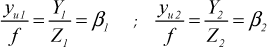
The image points, x
u1
and xu2, in the central image coordinates correspond with the projection of the points P1 and P2, whose distance is not strictly that of the ball diameters. So:


4.2 Ellipse Ball Projection Shape Correction
The second developed correction allows the ellipse axes to be calculated (this ellipse is the projection of the sphere onto the image) from the obtained values in the horizontal and vertical lines with an intersection in the ellipse centre (see figure 6). In figure 6, take note that x u1 and x u2 are not on the axis (the same for points y u1 and y u2 ) and so their use thereby negatively influences the determination of the sphere position (this is described in section 4.1). The objective is to obtain the major and minor axes of the projected ellipse in the image (a e , b e ) from the known information (x u1 and x u2 ). Once the semi-minor axis of the projected ellipse is calculated, the algorithm seen in section 4.1 is used in order to calculate the centre of the sphere definitively.

Ellipse of the sphere projection on the image plane
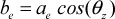
Figure 6 shows the error that occurs due to the projection deformation; it can be modelled if the angle θ
z
and the object position along the axis XC are known. θ
z
is the angle between the optical axis and the line that passes through the centre of the ball and the centre of the projected ball. Note that θ
z
coincides with the angle at which the image plane can be rotated around the minor axis of the ellipse in order to project a circle onto the plane image, thus:

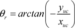


Angle θr
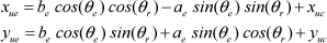
This allows the new values for the extreme points used in equations (2) and (6) to be calculated; then, the sphere centre position is calculated with equations (4) and (8), and so on. We could continue calculating this algorithm with the new data but it has been seen that the improvement is not appreciable after a second iteration.
4.3 Simulation of the effect of the proposed corrections
As previously described in sections 4.1 and 4.2, the proposed visual corrections improve the estimation of the three-dimensional position of the ball. In order to show this effect, a simulation has been carried out and the improvement is calculated and compared with non-use. There is a distance error between the actual position of the ball (known, since it is a simulation) and the position obtained with the algorithm. In figure 8, error decreasing is shown in mm. Normal working conditions for hitting the ball were simulated, assuming the ball is at a right rectangular prism with a depth of between 200 and 600 mm, and a horizontal and vertical displacement in the image plane of between −100 and 100 mm. Distances are measured from the optical centre of the camera. The simulation shows that in that zone, without corrections, the mean distance error is 7.78 mm, with a maximum of 22.03 mm. In contrast, with a correction in the same area, the mean distance error is 0.81 mm, with a maximum of 4.77 mm. In figure 8, the spatial distribution of the error decreasing (difference between previous distances) is represented in five parallel planes to the image, spaced every 100 mm. Higher values show a better performance of the proposed correction. The average decrease in the error is 6.96 mm and the maximum is 17.26 mm. The average decrease is greater when the camera is nearest to the ball, and the farther the optical axis is. If the ball moves farther laterally, the improvement is most significant; although it is not normal that this happens due to the tracking performed by the system. It is worth highlighting the good performance obtained due to the improvement, since the additional computation time required is negligible.
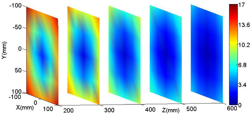
Distance error decreasing between the actual position of the ball and the position obtained with the algorithm (in mm)
5. Ball striking point determination
As explained in previous sections, the aim is for the robot to be able to indefinitely strike a Ping-Pong ball hanging from a thread bouncing against a flat wall. It is essential to control how that occurs in order to keep the ball inside the robot workspace. As a strategy, the ball is set to bounce against the wall at a predetermined point (centred with respect to the workspace of the robot). It hits at an angle close to 90 degrees. The robot with three translational degrees of freedom can only do this thanks to the spherically designed bat that correctly chooses the point where it has to hit the ball. This section explains in detail the algorithm designed to decide the hitting point and the position of the end effector when the hit is carried out.
For the design of the algorithm, the following considerations are set:
The study only takes into account the kinematic aspects and obviates the dynamic factors. The wall, on which the ball strikes, is assumed to be flat and parallel to both the camera and the base plane of the bat. Moreover, it is also assumed that the position of the wall is known to be relative to the robot coordinate system. The ball is hanging from a thread, but its trajectory has not been assumed as being pendulous. The actual obtained data discards such behaviour after performing the strike. The close proximity to the point of the strike is closer than a straight path. Likewise, when the ball bounces on the wall, the model used in the trajectory of the ball is a line, of which the angle of departure with respect to the normal angle at the point of strike is equal to the entrance angle with respect to the normal angle. The position information of the ball and its path are obtained using visual data, as described above. It should be taken into account that, due to the constant position of the camera on the bat, in positions that the ball is about to be hit, the ball disappears from the view of the camera and this thereby makes the estimates fairly accurate. In addition to the above considerations, the “spin” of the ball is neglected. Thus, it has been decided not to consider the spin for now but it will be dealt with in future works.
The following describes the algorithm in two phases and the tests performed. The first aims to bring the bouncing point of the ball on the wall to a position previously set, while the second phase features need such a rebound to occur at an angle close to 90 degrees.
5.1 Control of the rebound position on the wall
The aim of the first approach is to have, after successive bounces (between the bat and the wall), the ball rebound on the wall in a predetermined position (figure 9). Although the proposal has achieved this goal, it has some drawbacks such as an excessive variation of the incidence angle on the wall, which can cause the ball to end up outside the reach of the robot.

Successive bounces between the bat and the wall
Let us consider the scheme shown in figure 10, which represents a movement of the ball from a side view to the plane of the wall. The pink curve shows the trajectory of the ball in the direction of the bat, assuming that it comes from having rebounded on the wall or the initial impulse. P b is the striking point. The green line is the linear approximation to the trajectory at the point of striking, while P bp is the point on the wall from which the ball bounces if the trajectory were a straight path. The linear approximation of the exit path is shown in orange and will hit the wall at point P t . P tref represents the predetermined reference position, which it wants to reach. P c is the position of the centre of the bat; P n is the cut-off wall with the line passing through the centre of the bat and the striking point P b .
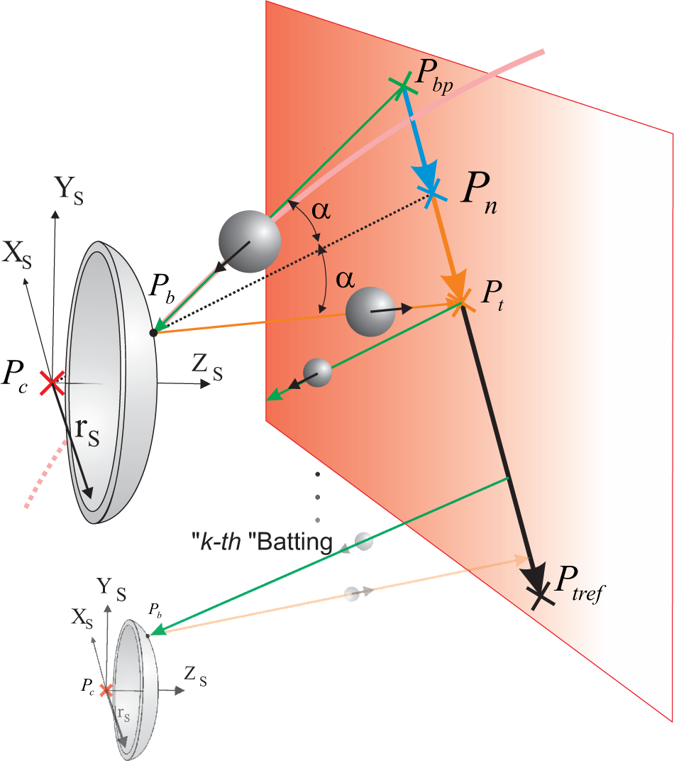
Elements used in the design of the controller. The section in pink represents the actual path of the ball, the green is the linear approximation and orange is the desired effect of the controller. It is represented by the point P b , the striking point, while P bp represents the position from which the straight path of the ball parts from the wall. P t represents the point at which the ball will come after a stroke of the bat, P n represents the point on the wall that is obtained by the algorithm control for the location of the centre of the bat P c , and, finally, P tref represents the point which it wants to reach after successive hits. No α angle is used in the formulation and it is only illustrative.
The aim is to design an algorithm to obtain P c only from knowing the trajectory of the ball and the rebound plane, which fixes P bp , and the striking strategy which sets an approximate value of P b (it would be accurate if the bat were flat).
Let us define the error in a particular hit as


It is also assumed that the following is satisfied:

This iterative process makes the rebound point close to the desired point. If the angle of the bounce is not controlled, it will cause an excessive variation of the said angle. Experimental tests demonstrate that improved performance is achieved with Λ=0.70
5.2 Control of the rebound position and the angle on the wall
In order to correct the perpendicularity between the wall and the trajectory of the ball, the error is reduced at each iteration, while a term is added to the previous algorithm which forces the bounce angle on the wall to change.
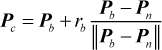
The perpendicular rebound will occur at the


Calculation of new point, P m . It uses the initial P n point and the projection on the wall, P bproj , of the hitting point on the bat P b . Then it is determined by the position of the centre of the bat, P c .
5.3 Results obtained
Here we will present a summary of the experiments performed to validate the algorithms developed. For an accurate description, different considerations are required:
Two landmarks on the wall are set: X
ref
= 100 and X
tref
= 0. The first one is centred on the position of the thread that holds the ball, but the second one is not. It thereby increases the difficulty of the control. Initial position of the ball. The ball is thrown from a position fixed to the robot, which can be centred (C) or lateral (L). The lateral distance in this case is 180 mm. The robot's speed at the moment of striking is close to 2 m/s, whereas the estimated maximum speed of the ball was 3.7 m/s.
Indices obtained for each experiment. Twenty tests were performed with 24 strikes each.

Mean of absolute error values (|E t |) for the 24 strikes of the 20 tests. It is only considered as the error in the X axis of the bat. The Z axis error is zero due to the position of the wall, and is not controllable on the Y axis, because it depends on the thread. It is expressed in millimetres.
Mean of absolute error values (|E t |) for the last 12 strikes of the 20 tests. The error is considered only in the X axis of the racket. It provides the permanent regime information obtained in the tests. It is expressed in millimetres.
Mean of absolute values of the wall rebound angle (|β t |) for 24 strikes of the 20 tests. This angle is obtained by the scalar product of the trajectory of the ball with the normal angle to the plane of the wall. It is expressed in degrees.
The mean of the absolute values of the wall rebound angle (|β t |) for the last 12 strikes of the 20 tests. It provides permanent information of the regime obtained in the tests. It is expressed in degrees.
The improvement from using algorithm 2 can be seen in both the error and in the angle. The permanent regime state values retain very low limits.
Figure 12 shows the position of the robot and the ball trajectories when using the algorithm that controls the position and angle of the bounce on the wall with a lateral throw. The positions of the centre of the bat are shown in black and the trajectories described by the ball after the 24 beatings that comprise the test are shown in red.

Robot position and ball trajectories when the algorithm that controls the rebound position and angle with a lateral throw is used. Black: Position of the end effector. Red: position of the ball.
Some videos of the RoboTenis system in tracking tasks (such as playing Ping-Pong) are shown at: http://www.disam.upm.es/vision/projects/robotenis/indexI.html
6. Conclusions
The strategy for RoboTenis, a parallel robot that is able to hit a ball hanging from a thread, is described in this paper. Besides the construction of the system, we also describe how a spherical bat is able to direct the hitting of the ball despite using a robot with only three degrees of translational freedom. This can be carried out only if the ball is detected with good accuracy (which includes the correction caused by the projection of the ball), and with a strategy to select the point of hitting the ball on the bat to achieve the compliance objectives (direct the ball to a specific area). The contribution of the paper focuses on these three aspects. Furthermore, this highlights the need for an effective visual control algorithm with a high dynamic performance, able to adapt to a real system (saturation, noise, delay).
For future work, the integration of a camera capable of operating at 300 FPS is currently being attempted. Eliminating any restrictions on the movement of the ball, such as having it hung by a thread, will also be studied.
Footnotes
7. Acknowledgements
The authors would like to thank the following institutions for their financial support: Universidad Politécnica de Madrid in Madrid Spain; Universidad Aeronáutica de Querétaro, in Queretaro Mexico; and Universidad Nacional de San Juan in San Juan, Argentina. This work was supported by the Ministerio de Ciencia e Innovación of the Spanish Government under Project DPI2010–20863 and the Comunidad de Madrid under Project S2009/DPI-1559.