
Abstract
This paper presents the complete calibration procedure of a multi-camera system for mobile robot motion registration. Optimization-based, purely visual methods for the estimation of the relative poses of the motion registration system cameras, as well as the relative poses of the cameras and markers placed on the mobile robot were proposed. The introduced methods were applied to the calibration of the system and the quality of the obtained results was evaluated. The obtained results compare favourably with the state of the art solutions, allowing the use of the considered motion registration system for the accurate reconstruction of the mobile robot trajectory and to register new datasets suitable for the benchmarking of indoor, visual-based navigation algorithms.
Introduction
Multi-camera systems used for the tracking of markers, both natural and artificial, are commonly used in the field of computer vision. Such systems allow for the estimation of the pose of the marker attached to a moving object and for the reconstruction of its path from the series of such measurements. The trajectory that is carefully reconstructed using such data is often used for tracking and localization in the context of surveillance [1] [2], wildlife monitoring [3] and finally, the tracking and localization of mobile robots [4] [5]. One of the most important uses for multi-camera video data in the field of mobile robotics is the evaluation of mobile robot navigation algorithms. While benchmarking navigation algorithms in outdoor applications is in most cases performed using global positioning system (GPS) data [6] [7] [8], GPS localization accuracy degrades quickly as the signal quality gets worse. Furthermore, GPS positioning in general does not work inside buildings. In such a case, vision-based assessment of the accuracy of navigation algorithms becomes the most attractive solution. As such systems are often composed of multiple cameras, the calibration of such multi-camera setups and the accuracy of the reconstruction of the robot pose are crucial. Moreover, mobile robots are often equipped with multiple sensors and markers of different types. This is why the estimation of spatial relationships between the sensors and the markers, as well as their relation to the robot reference frame must be performed [9] [10] [11]. Failure to do so leads to gross errors.
In [12] and [13], the authors present multi-camera systems capable of tracking multiple robots. The systems use no or minimum artificial markers for the identification of the tracked objects and the tracking process allows only for the reconstruction of the paths of the robots with limited information on orientation. The proposed applications of the systems are constrained to the tracking of movement over a two-dimensional surface, and the goal of the calibration is to provide correct camera handoff. A markerless solution for 3D robot tracking is presented in [4]. The position of the robot in multiple views is detected by motion segmentation and the 3D localization is based on the minimization of a cost function. Camera calibration, both intrinsic and extrinsic, is necessary to properly place the tracked object in the 3D space. While the method is general, the accuracy is not sufficient for the ground-truth data generation. A different approach is presented in [14] and [15]. These methods rely on natural image features found in the registration environment. The cameras are calibrated using multiple view geometry methods followed by bundle adjustment. The solution presented in [14] is even capable of automatic discovery of the spatial relations between multiple cameras attached to a common, rigid frame. However, in order to do so it relies on odometry measurements. Marker-based multiple camera calibration is more commonly applied in multi-camera surveillance systems and is required for multi-camera object tracking and handoff [1] [16]. However, in general, object tracking in such systems does not include orientation tracking, as such information is not necessary from the point of view of the end application.
Failure to provide the correct calibration data may cause large parts of the dataset to become unreliable and unusable. The dataset gathered during the Rawseeds Project [5] is one of the most widely used when it comes to the benchmarking of the simultaneous localization and mapping systems as it incorporates data from numerous sensors including four cameras. The procedure of the cameras' relative poses estimation was only vaguely described in the project reports.
Unfortunately, the provided relative poses of the cameras significantly differ from the poses estimated from the video sequences, thus rendering the usefulness of the dataset doubtful. To confirm this, we performed a simple experiment using the images provided in the Rawseeds database. In this experiment, the relative pose of the cameras was estimated by matching image features detected and described using the ORB algorithm[17]. The 8-point algorithm [18] combined with the LMedS framework[19] was used to calculate the essential matrix, from which the rotation and translation components were extracted [20] [18]. Figure 1 presents the feature matches used for the estimation of the essential matrix. Table 1 presents the rotation and the unitary translation vectors describing the transformation between two of the cameras used in the Rawseeds Project. There is a clear difference in the results given in the database description and the results returned by the algorithm estimating the scene structure. The same situation was observed for multiple pairs of images in the database.

The feature matches used for essential matrix estimation
The rotation (rx, ry, rz) and translation (tx, ty, tz) between the cameras SVS_R and SVS_L of the Rawseeds Project

The results of this experiment show that a precise description of the calibration process is an important part of the procedure, as without it is impossible to reliably reproduce the achieved results and identify the sources of possible discrepancies.
In this article, we present a method for the calibration of the multi-camera registration system for visual navigation benchmarking. The calibration allows us to capture the spatial relationships between the cameras observing the robot, thereby allowing for accurate path reconstruction. Moreover, the method for the estimation of the spatial arrangement of sensors and markers with respect to the mobile robot frame is also presented. The acquired data allows reliable benchmarking of the algorithms performing the task of simultaneous localization and mapping (SLAM) [21] [22] or visual odometry [23] [24]. As shown in [25], the presence of additional structured markers placed throughout the environment improves the accuracy of navigation in single robot scenarios. We believe that the introduction of additional unique artificial markers associated with individual robots, as presented in this article, will allow us to improve the accuracy in scenarios in which external cameras are used or in the case of collaborative SLAM.
Motion capture subsystem architecture
The considered motion capture system (MCS) consists of five high-resolution Basler acA1600 cameras equipped with low-distortion, aspherical 3.5mm lenses. The cameras are mounted under the ceiling of the laboratory, forming an X-like structure. The field of view (FOV) of the central camera partially overlaps with the FOVs of all the peripheral cameras. Moreover, the FOV of each of the peripheral cameras partially overlaps with FOV of the two neighbouring peripheral cameras. Figure 2 presents the alignment of the cameras while Figure 3 presents the concept of overlapping FOVs

The motion capture system camera layout
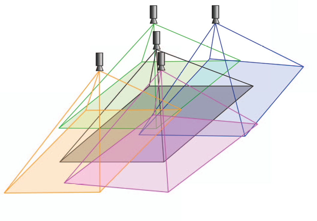
The overlapping FOVs
The MCS coordinate system is coincident with the coordinate system of the central camera. The rotation matrix and translation vector of the peripheral cameras with regard to the MCS frame are defined as R C P i and t C P i , where C stands for the central camera and Pi represents the i-th peripheral camera.
A WiFiBot Lab V3 robot is used as the mobile platform in the registration system. In order to provide a wide field of view and to gather data for stereo-vision algorithms, two Basler acA640 cameras with 3.5mm lenses are installed on the robot using adjustable camera mounts. A rigid frame with a chessboard marker is attached to the robot, allowing us to track the robot's position. Two additional circular markers are installed on the sides of the robot to facilitate research on the vision-based cooperation algorithms. The robot is shown in Figure 4.

The modified WiFiBot Lab V3 robot
As the MCS provides the information on the position of the chessboard marker, it is assumed that the robot's coordinate system is defined by the chessboard marker. The pose of the on-board cameras with regard to the robot's frame is defined by the rotation matrix R R R i and the translation vector t R R i , where R stands for the robot coordinates and Ri is the frame of the i-th robot camera. Similarly, the rotation matrix and translation vector of the circular markers are defined as R R M i and t R M i , with Mi standing for the i-th marker.
The registration system used for ground truth data gathering is set up to achieve maximum possible accuracy. The snapshots taken every 100 ms by both the overhead and robot-mounted cameras are synchronized to under 1 ms. Thanks to such a solution, there is no need to interpolate the measurement data, which is an advantage over timestamp-based solutions presented in [5] [7] [26]. Synchronized acquisition of uncompressed images at such data rates is a challenging task. To provide bottleneck-free communication and registration, dedicated GigE Vision acquisition cards were used for the data transmission and SSD, and RAM-disks were used as storage. The detailed presentation of the whole system used for data acquisition is outside of the scope of this article and can be found in [27].
Camera calibration
The camera calibration is a necessary step in 3D computer vision allowing the extraction of metric information from 2D images. The intrinsic parameters and the distortion coefficients of the cameras used in the registration system are estimated independently for each camera using the method proposed in [28]. The input data for the method are the images of a planar pattern with distinct features observed by the camera shown at several different orientations. The orientation change can be performed by moving either the camera or the marker, yet no prior knowledge on the motion is necessary for correct operation. The calibration procedure assumes that the 3D world points are projected on the camera image plane according to the rational camera model described in [29].
The projection function is defined as:
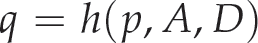
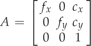

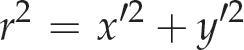
where p = [x y z] T stands for the Cartesian position of the point in the camera coordinates, q = [u v] T is its position on the image plane, A is the camera matrix, ki is the i-th radial distortion coefficient and pi stands for the i-th tangential distortion coefficient. The elements of the matrix A are the focal lengths in the x and y directions denoted as fx, fy (as in the general case the pixels can be non-square), and the coordinates of the principal point of the camera are denoted as cx and cy. The image position of a 3D point p is calculated according to the following formulae:


The image coordinates of the chessboard marker's corners detected on the images registered using the camera that is to be calibrated are used as the input data. Prior knowledge on the arrangement of the feature points on the planar pattern enables us to establish the correspondences between the observed features and the pattern features. The goal of the procedure is to find the set of intrinsic parameters and the distortion coefficients that assure the coincidence of these two sets of features. The procedure starts with finding a closed-form solution, which is then used as the starting point for nonlinear refinement based on the maximum likelihood criterion. The implementation of the algorithm is readily available in the OpenCV image processing library [30].
As required by the method, a planar marker with a chessboard pattern is used for the calibration. A number of calibration marker images are gathered for each of the cameras covering a diverse set of relative marker-camera poses. Half of the images are used as a calibration set, while the other half are used only for testing. Figure 5 presents the exemplary images used for the calibration.
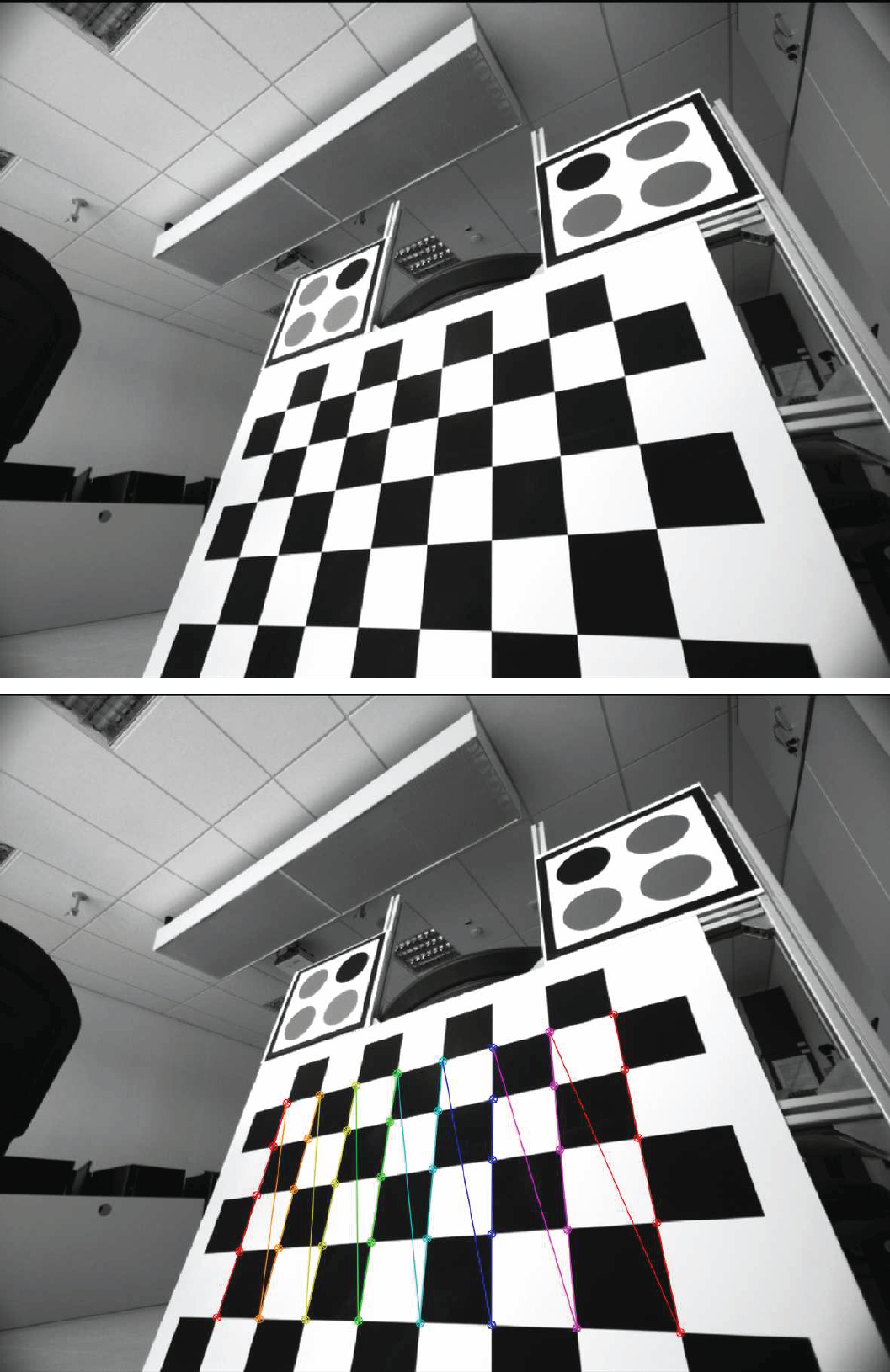
Exemplary image used for the camera calibration (top) and the same image with the pattern features detected and marked (bottom)
The estimated intrinsic parameters and the average reprojection error of the MCS and the robot cameras, as well as the additional camera (E) used in the robot calibration (see Section 4.2) are presented in Table 2.
The intrinsic parameters of the cemeras used

Motion capture system calibration
The knowledge of the exact position of the cameras with regard to the MCS coordinates coincident with the central camera coordinates is required in order to precisely track the robot's position. As the FOVs of all the peripheral cameras partially overlap with the FOV of the central camera, the simplest way to estimate their relative position is to use the available stereo-calibration procedures. Unfortunately, such an approach can lead to inconsistency of the relative position of the peripheral cameras, as the position of each camera is estimated independently.
In order to overcome this problem, a holistic approach to simultaneously estimate the pose of all the peripheral cameras was developed. The proposed method uses observations of a chessboard calibration marker visible by at least two cameras at the same moment (Figure 6).

The calibration marker observed simultaneously by three cameras
The model parameters vector β MCS consists of the poses of the peripheral cameras and the poses of the calibration marker during consequent observations:

where
The Levenberg-Marquardt algorithm [31] [32] is used to minimize the root mean square (RMS) of distances between the observed and the predicted positions of chessboard marker corners on the registered images:
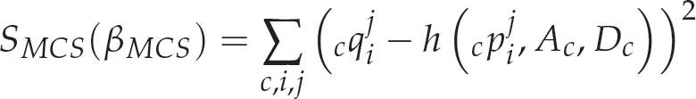
where c q i j is the position of the j-th calibration marker point on the i-th image registered by the camera c ∊ [C, P1, P2, P3, P4], c p i j is the position of the point in the camera coordinates, Ac and Dc are camera matrix and distortion coefficients of the camera c.
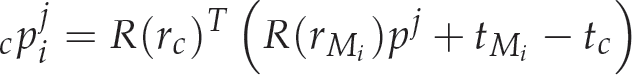
The position of the j-th calibration marker point in the cameras' coordinate frames for i-th pose of the calibration marker is defined as:


where R(r) stands for the rotation matrix defined by the Rodrigues' rotation vector r and pj is the position of the j-th point in the marker coordinates.
It is worth noting that each of the predicted point projections depends only on the pose of the calibration marker during the particular observation and optionally on the pose of one of the peripheral cameras. Therefore, the Jacobian matrix of the minimized function over the parameters vector β MCS is sparse. Moreover, its elements can be calculated analytically which significantly speeds up the optimization procedure.
The MCS allows us to precisely track the pose of the calibration marker attached to the mobile robot. In order to track the pose of the on-board cameras, it is necessary to calculate their position with regard to the robot's calibration marker. As mechanical measurements would be cumbersome and imprecise, a visual method using an external camera and an additional calibration marker is proposed. The additional marker is placed in the field of view of the on-board cameras and the external camera is used to register an image with both the robot and the additional marker visible (Figure 7). A diverse set of images with different marker and external camera poses is registered (Figure 8).

The robot camera calibration

The exemplary images used for the calibration of the robot camera poses: the on-board cameras (left) and the external camera (right)
The model parameters vector β RC consists of the poses of the robot cameras and the poses of both the external marker and the external camera during consecutive observations:

where r R i and t P i stand for the orientation described using the Rodrigues' rotation formula and the translation vector of the i-th robot camera respectively. Analogously, r M i , t M i , r E i , t E i represent the pose of the external calibration marker and the external camera during the i-th observation.
Similarly to the MCS calibration, the Levenberg-Marquardt algorithm [31] [32] is used to minimize the RMS of distances between the observed and the predicted positions of marker corners on the registered images:

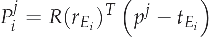
where c q i j is the position of the j-th external calibration marker point on the i-th image registered by the camera c ∊ [R1, R2, E], c p i j is the position of the point in the camera coordinates, Q i j stands for the position of the j-th point of the robot marker on the i-th image registered by the external camera, and P i j is the position of this point in the external camera coordinates.
The position of the j-th external marker point in the camera c coordinate systems is defined as:
and the position of the j-th robot marker points in the external camera is calculated according to:
Similarly to the MCS calibration, each of the predicted projections of the external marker points depends only on the pose of the external marker during the particular observation and on the pose of one of the cameras. The projections of the robot marker points depend only on the pose of the external camera during the particular observation. Therefore, the Jacobian matrix of the minimized function over the parameters vector β RC is sparse. Its elements can also be calculated analytically which significantly speeds up the optimization procedure.
In order to use the circular patterns in the cooperative, vision-based algorithms, their exact pose with regard to the robot's coordinate frame has to be established. The relative pose is calculated using a series of images with both the chessboard marker and the circular marker visible. A set of images taken at different camera poses was recorded (Figure 9).

An examplary image used for the robot marker calibration
The parameters vector β RM of the model consists of the pose of the circular pattern marker and the poses of camera during subsequent observations:

where rM and tM stand for the Rodrigues' rotation and translation vectors of the k-th robot marker respectively, while
The Levenberg-Marquardt algorithm [31] [32] is used to minimize the RMS of differences between the observed and the predicted positions of both the chessboard marker corners and the centres of the circular pattern on the registered images:

where q i j is the position of the j-th chessboard marker corner on the i-th image registered by the external camera p i j is the position of the point in the camera coordinates, Q i j stands for the position of the j-th circle centre of the circular marker on the i-th image registered by the external camera, and P i j is the position of this point in the external camera coordinates.
The position of the j-th chessboard corner in the external camera coordinate systems is defined as:

and the position of the j-th circular marker centre in the external camera is calculated according to the following formula:

The position of the chessboard corners depends only on the relative pose of the camera, while the position of the circular pattern points depend on both the pose of the camera and the pose of the circular marker. The Jacobian with regard to the model parameters is sparse and easily computable which significantly facilitates the optimization process.
Motion capture system calibration
The data required to perform the calibration of the MCS was gathered by registering the images of a 5 × 8 chessboard calibration marker in 362 different poses in which it was observed by at least two cameras. Half of those images were used to calibrate the MCS according to the procedure described in Section 4.1 The other half, constituting the first testing set, was used for the evaluation of the obtained results. Additionally, the images of the mobile robot carrying a 4 × 6 chessboard marker in 180 poses were registered forming the second testing set. The initial poses of the marker w.r.t the cameras' coordinate systems required for the calibration procedure were established independently for each image using the Levenberg-Marquardt algorithm [31] [32].
Figure 10 presents the estimated poses of the MCS cameras as well as the poses of the marker used for calibration. The numerical values of the obtained rotation and translation vectors are given in Table 3.

The estimated poses of the cameras and calibration marker with regard to the central camera; [m] stands for metres
The rotation (rx, ry, rz) and translation (tx, ty, tz) vectors of the peripheral cameras obtained using the proposed method

The RMS of the chessboard pattern corners' reprojection error on the calibration set equalled 0.1487 pixel. The two testing sets were used to evaluate the quality of calibration results. The mean discrepancy of the chessboard marker corners' 3D position estimated from the images registered by different cameras and recalculated to the global coordinates was selected as a quality measure:


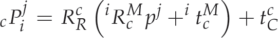
where c P i j is the position of the j-th calibration pattern point observed at i-th image by the camera c, R C c and t c C describe the transformation between the camera c and the central camera estimated by using the proposed calibration method (for c = C R C C is an identity matrix and t C C is a zero vector). i R c M and i t c M describe the pose of the marker with regard to the camera frame estimated as a solution to the PnP problem from the i-th frame by using algorithm described in [33]. The c1 and c2 are two cameras observing the marker at the same time. Figure 11 presents the histogram of point position discrepancy obtained for the first testing set, while the Figure 12 presents the histogram of discrepancy for the marker placed on the robot.
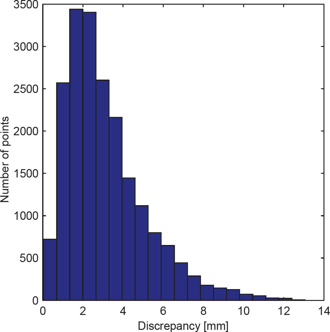
The histogram of points position discrepancy in the testing set

The histogram of points position discrepancy for the robot marker tracking
The mean discrepancy between the robot marker corners' positions estimated from images registered by different cameras equalled 0.013[m] (Table 4) which allows reliable tracking of the robot's position and calculating its ground truth position.
The mean, standard deviation and maximum discrepancy

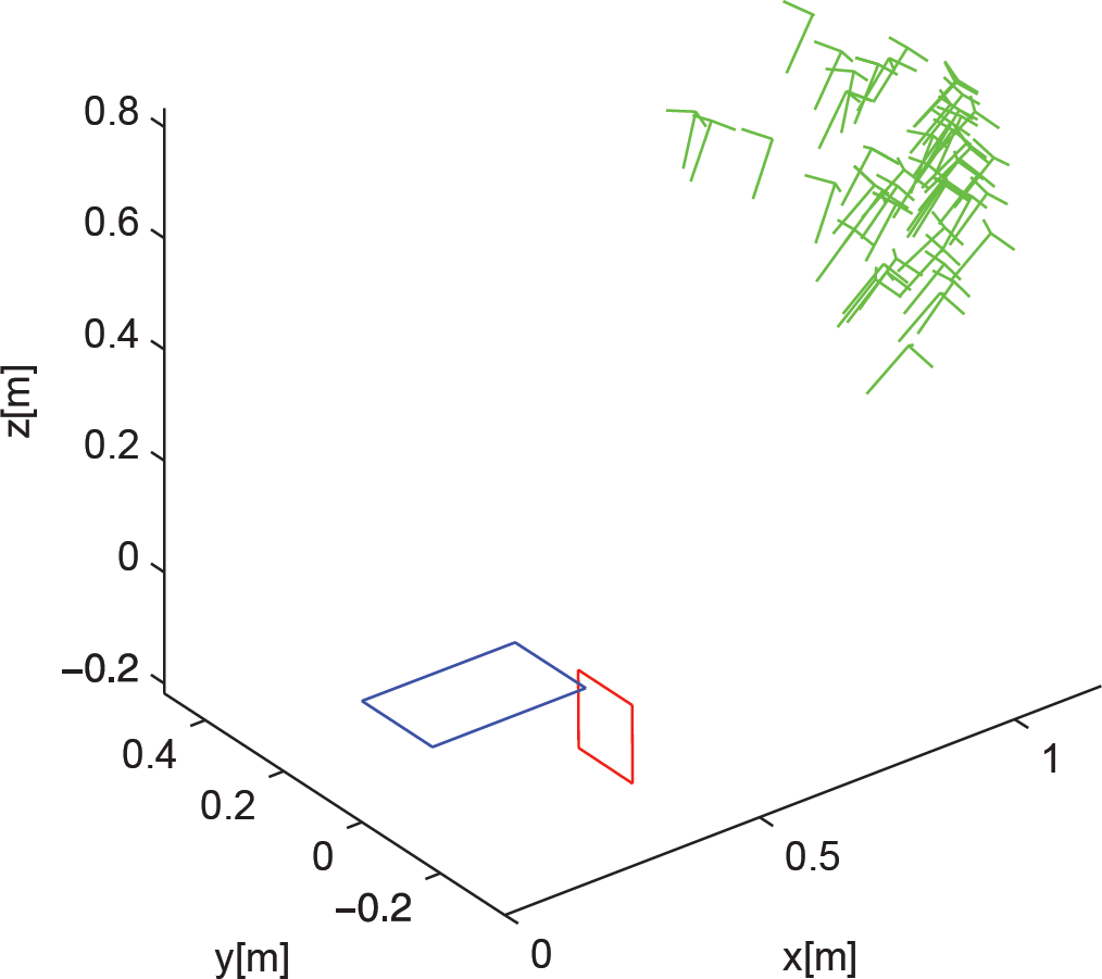
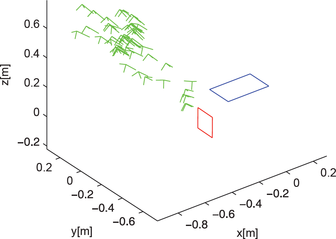
A set of images was recorded with the robot's on-board cameras and the external camera in 50 combinations of the external marker and the external camera poses. 40 of the image groups were used for calibration while the rest was used to evaluate the results. The method presented in Section 4.2 is used to determine the pose of the robot cameras. The final RMS of the reprojection error equalled 0.02 pixel. Figure 13 presents the 3D plot of relative camera and marker poses, while Table 5 contains the numerical values on the robot's cameras position and orientation.

The result of robot cameras calibration: robot marker - black, robot cameras - blue, external camera poses - red, external marker poses - green; [m] stands for metres
The rotation (rx, ry, rz) and translation (tx, ty, tz) vectors of the robot cameras obtained using the proposed method; [m] stands for metres

In order to evaluate the calibration process, the mean discrepancy between the estimated 3D positions of the external chessboard pattern corners with regard to the robot's coordinates was calculated.
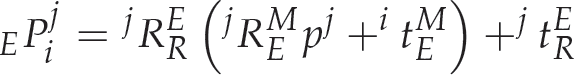

where c P i j is the position of the j-th calibration pattern point observed at i-th image by the robot camera c, R c R and t c R describe the estimated transformation between the robot camera c and the robot coordinates. i R c M and i t c M describe the pose of the marker with regard to the camera frame estimated as a solution to the PnP problem from a frame i using algorithm described in [33]. The c1 and c2 are two cameras observing the marker at the same time. Figure 14 shows the histogram of discrepancy between point positions estimated by the robot cameras. Figure 15 shows the histogram of discrepancy between the point positions estimated with the robot cameras and the external cameras.

The histogram of points position discrepancy between the robot cameras; [mm] stands for millimetres

The histogram of points position discrepancy between the robot cameras and the external camera; [mm] stands for millimetres
The pose of each of the circular patterns was calculated independently. For each pattern a set of 50 images with both the chessboard pattern and the circular pattern marker of interest was recorded. The procedure described in Section 4.2 was applied to determine the pose of the circular pattern markers. The final RMS of the reprojection error equalled 0.021 pixel for the right marker and 0.025 pixel for the left pattern. Figures 16 and 17 show the relative poses of the markers and the external camera, while Table 6 contains the values of the marker translation and rotation vectors.
The calibration of the right circular pattern marker: chessboard marker - black, circular pattern marker - red, external camera poses - green; [m] stands for metres
The calibration of the right circular pattern marker: chessboard marker - blue, circular pattern marker - red, external camera poses - green; [m] stands for metres
The poses of the circular pattern markers obtained using the proposed method; [m] stands for metres

This paper presents the calibration procedures of the three main components of the mobile robot movement registration system:
estimation of relative poses of motion capture system cameras,
estimation of robot camera poses with regard to the marker attached to the robot,
estimation of additional marker poses with regard to the robot coordinates.
All the proposed methods use visual observations of the calibration markers and employ a Levenberg-Marquardt optimization algorithm to minimize the RMS of the reprojection error. The use of an additional, robot-mounted marker allows us to recover both the position and orientation of the robot with regard to the global reference frame with very good accuracy.
When compared to markerless methods, e.g., [4], the accuracy is over an order of magnitude better. Moreover, unlike the solutions presented in [13] and [12], it facilitates full pose recovery. The reliable observation of the robot-mounted marker may however be impossible or unfeasible in vast spaces – in such a case the calibration and tracking solutions based on natural features like [14] or [15] are a better choice, provided that there are enough natural features available for tracking. It is also worth noting that the methods based on multiple view geometry and bundle adjustment require the cameras to be calibrated to move [14] [15]. Additional data, such as wheel odometry measurements, may also be required for the discovery of the extrinsic parameters of the camera system [14]. On the contrary, the presented system is completely passive, as the observations are performed by environment-bound sensors, i.e., the ceiling cameras.
The obtained calibration precision will allow the gathering of a reliable dataset for evaluation of indoor mono- and stereo-based visual navigation algorithms. The data used for the calibration will be made freely available along with the gathered robot trajectories in order to facilitate result reproducibility and the development of different calibration methods.
Footnotes
7.
This research was financed by the Polish National Science Centre grant funded according to decision DEC-2011/01/N/ST7/05940, which is gratefully acknowledged.