
Abstract
This paper establishes an approach to external force estimation for telerobotic control in radioactive environments by the use of an identified manipulator model and pressure sensors, without employing a force/torque sensor. The advantages of - and need for - force feedback have been well-established in the field of telerobotics, where electrical and back-drivable manipulators have traditionally been used. This research proposes a methodology employing hydraulic robots for telerobotics tasks based on a model identification scheme. Comparative results of a force sensor and the proposed approach using a hydraulic telemanipulator are presented under different conditions. This approach not only presents a cost effective solution but also a methodology for force estimation in radioactive environments, where the dose rates limit the use of electronic devices such as sensing equipment.
1. Introduction
Telerobotics solutions for radioactive environments have been researched in detail since the first developments carried out by Goertz for the US Atomic Energy Commission [1] with the aim of avoiding human intervention. In teleoperation, a haptic master device is linked to the operator's movements in the local environment while the slave device, situated in the remote environment, mimics the movements of the master. Providing the operator with information about the remote environment, such as position, orientation, forces etc., improves the operator's understanding of the remote environment and, therefore, the task performance. The operator's quality of perception quality is often termed ‘transparency’ and, together with stability, is defined as one of the major goals of telerobotic performance. A condition of transparency is achieved if the human operator feels the same impedance in the master as the robot when interacting with the remote environment [2], while stability is a well-established condition of every control system. Information from the remote environment can be viewed on display screens [3], but it is more intuitive when supplemented by reflecting measured parameters such as positions and forces to the haptic master device. When the operator interacts with the slave via a haptic master, then the operator is said to be ‘kinaesthetically coupled’ to the environment and - similarly - the task being performed is said to be ‘bilaterally controlled’ [4, 5]. Continued advances in various fields of control, communications and haptic systems [6, 7], among others, have made it possible to implement an integrated robotic master-slave system that is able to aid the human operator in effective task execution, especially under hazardous conditions which impede human access. This research discusses methodologies to reduce human intervention in hostile environments, especially those producing ionizing radiation. These environments primarily comprise nuclear facilities and large scientific facilities focusing on nuclear research.
The first telemanipulators were linked either mechanically or else by using mechanical switches. More recent work carried out by the Oak National Laboratory developed the first electronic master-slave system with force feedback for military, space and nuclear applications [1]. In addition, for nuclear applications, the Commission de Energie Atomique (CEA) in France developed the MA 23, demonstrating bilateral manipulation tasks to reduce human exposure to radiation [8]. Large scientific experiments such as CERN (European Organization for Nuclear Research) [9] and JET (Joint European Torus) [9–12] require telerobotics solutions in areas where ionizing radiation and hazardous conditions make it difficult or else impede human intervention. At JET, remote handling operations have been carried out since the late-1990s by using a Mascot servo-manipulator transported by the JET articulated boom [9]. This manipulator provides force feedback to a kinematically identical master by means of applying a force proportional to the positional error. At CERN, some examples of remote manipulation were developed for the TIM robot [12] and the Mantis mobile platform [13] (also based on the Mascot manipulator). For the next generation of ITER-like (International Thermonuclear Experimental Reactor) fusion reactors, more demanding radiation conditions are expected and new hydraulic manipulators are being developed (e.g., [14] and [15, 16] together with rad-hard modifications of COTS manipulators [7]).
Traditionally, such manipulators can be characterized by being easily back-drivable, which is a key requirement for the application of force feedback control based on positional error [17]. More recent strategies have been based on the use of force/torque sensors attached to the end-effector to estimate the environmental forces and reproduce them in the master by employing a force-position algorithm or a four channel bilateral control [6, 18]. Even though the most advanced sensors present very low levels of noise, some techniques have been developed to reduce this noise based on sensor fusion [19–20]. In some cases, the position at which the external force is applied is a priori unknown and may be on a robot link (as opposed to on the end-effector). Besides requiring additional wiring in the robot, these force sensors cannot withstand the high dose rates of the high energy scientific facilities [5]. Moreover, force sensors can be expensive and can increase the production cost of the robot. For these reasons, employing a disturbance estimation scheme for external, force-sensorless robot teleoperation has been a feasible option. Disturbance observers have been widely proposed for motion control and collision control applications [21–23], for determining disturbance forces such as friction. Ohishi et al. proposed a force estimation method based on observers for robotics applications [24–26]. In this scheme, the modelling uncertainties were estimated with previously obtained experimental data, and the external torques were obtained by subtracting the established modelled uncertainties from the output of the disturbance observer. Their approach has the advantage of not requiring an accurate robot model, but it instead needs a nominal model. It was tested on a 2-DOF robot. Different approaches based on robustly stable disturbance observers [27–31] have focused on avoiding the smaller stability margins of the disturbance observers during motion control [32]. A force observer is presented in [33], where it is demonstrated that for small accelerations the external force is proportional to the observation error as long as the model is accurate. Other techniques based on Ohishi's previous work have employed the adaptive disturbance observer scheme [34] and have tested the proposed method for a 2-DOF planar robot.
The research in this paper extends [35] and [33] to obtain force values from the equivalent disturbance signal on a hydraulic manipulator, where the uncertain parameters are estimated by using least mean squares (LMS). The proposed method is then applied to a 6-DOF articulated robot for different scenarios, similar to those required for remote-handling operations.
This paper is organized as follows. In Section 2 the construction of the force estimator is explained. In Section 3 the experimental design is shown. Section 4 details the experimental setup prepared with a Kraft hydraulic manipulator. The experimental results are given in Section 5 and final conclusions are presented in Section 6.
2. External force estimator
As the forces and torques applied to the master are proportional to those applied to the slave in bilateral control using a force channel, the estimation of the robot end-effector torques in a sensorless system is crucial. In this paper, to obtain the force information from the disturbance signal, the modelling uncertainties are modelled by using the robot dynamic equation (1):

where,
τ m : denotes the vector of motor torques exerted in each joint.
H: is the robot inertia matrix.
C: is the Coriolis forces vector.
τ g : is the gravity forces vector.
τ f : is the friction torques vector.
τ ext : is the external torques vector on each joint produced by the external forces on the end-effector.
The external forces can be estimated by applying the kinematic information contained in the robot Jacobian, obtaining (2):
where,
T: denotes the vector of forces and torques exerted in the robot end-effector and expressed in the base coordinates system.
J: is the robot Jacobian, with “†” denoting the matrix inverse (or pseudo-inverse when corresponds).
On a hydraulic actuator based on servo-valves, the motor torque τ m can be estimated by using the expression on (3) [36], where Kp is a constant and AP is the differential pressure between the two chambers of the hydraulic actuator:

2.1 Robot modelling
The conventional robotics equation describing the inner forces (4) of a kinematic chain of rigid forces in the absence of external forces can be obtained by employing any established algorithm (e.g., the Newton-Euler iterative method or the Lagrangian method):

By adding the friction term to (4) and employing the modified Newton-Euler method described in [37], it is possible to yield a model of the form:

Although the friction is a complex non-linear phenomenon, in many robotics applications it is modelled by considering only the Coulomb term and viscous friction, thus yielding:
This expression of the friction maintains the linear model and ensures the application of the linear estimators. In (5), the motor torque is also linear with the inertial parameters. This expression is particularly interesting in using an estimator like LMS to identify the robot's inertial parameters. With this in mind, equation (5) is expressed by the product of a n x 10n matrix - termed the ‘observation matrix’ - and a vector·ø i of parameters with size n x 1 obtaining (7). Where n is the number of degrees of freedom of the robotic system:

It is common among some manipulators - especially those with bigger payloads - to include a closed-loop in the serial chain to allow for the placement of one actuator closer to the base, thus making it possible to distribute the mass symmetrically. Therefore, the problem of yielding to a model described by (7) needs to take into account the closed-loop. In order to do that, a loop closure function is applied to the tree dynamics obtained by – for example - the Newton-Euler algorithm. If q is the vector of the joint values for the spanning tree of a given closed-loop system, and let y be a vector of independent joint variables for the same system. It is possible to define the relationship thus:

Differentiating this equation as in [38] yields:

with:

G is the loop closure function. We define G u and G0 as containing the rows of the actuated and unactuated freedoms, respectively. These matrices are related to G by an n x n permutation matrix designed by Q leading to equation (11).

It was shown in [38] than the torque of the y joints can be calculated by having the tree torques, τ ID , and applying (12) if the system is properly actuated. This is if G u is invertible and, therefore, if there is a unique solution:

Replacing τ ID in (12) by its equivalent product of the observation matrix and the vector of the parameters yields the expression in (13), where A i will contain the kinematic information corresponding with the tree and ø i will contain the vector of tree parameters:

3. Experiment design
The implementation of the method described in this paper consists of two different steps. The first is the modelling process, involving the characterization of the actuators and identification experiments. The second is the implementation of the algorithms for real-time operation.
In teleoperation, the delay issue becomes crucial since the external forces and torques have to be perceived with the minimum delay in order to guarantee stability and transparency in the system [39]. Appropriate algorithms must be used in order to estimate the external forces acting on the system, with a compromise between accuracy and delay.
3.1 Trajectory parameterization, robot excitation and position differentiation
Several techniques have been applied to trajectory parameterization for robot dynamic model identification (e.g., finite sequences of joints' accelerations [40], fifth-order polynomials and periodic trajectories [41]). The polynomial technique is adequate for industrial manipulators that only accept velocity commands, while periodic trajectory is more suitable for open control systems.
In this paper, a trajectory that can be parameterized by a finite Fourier series is employed, since processing a periodic and band-limited measure is more accurate and has more advantages in terms of signal processing [42]. Thus, each robotic joint is parameterized as follows:

where t is time and ω f is the fundamental frequency of the excitation trajectories, which should be chosen carefully so as not to excite the un-modelled dynamics of the manipulator. The coefficients a i,k and b i,k are the amplitudes of the sine and cosine functions, and qi0 is the joint offset. By selecting appropriate values for the amplitudes and the fundamental frequency, the joint workspace varies with the joint speed. In this paper, different frequencies were utilized covering the maximum joint positional and acceleration ranges without compromising the robot's structural flexibility.
The problem of finding the coefficients a i,k , b i,k and qi0 is called ‘trajectory optimization’, and several approaches have been used. A popular optimization criterion is ‘d-optimality’, based on the logarithm of the determinant of the covariance matrix of the model parameter estimation [42]. Other methods are centred on minimizing cost functions which are dependent on the condition number and the singular values of the observation matrix. In order to simplify the high complexity of the optimization process, an alternative method has been performed based on the determination of trial and error parameters, followed by a discard process of those points which ensure that the condition number of the observation matrix is above a certain threshold, this value has been established on 100 from experience of the statistical community [8]:

The calculated trajectories are programmed in the robot controller. The robot repeats the trajectory over a certain number of periods while the measured joints values are acquired by the DAQ system. The calculation of the observation matrix requires the estimation of the joints' velocities and accelerations. Since most manipulators do not have accelerometers, a numerical differentiation must be carried out. The approach employed here is based on a well-established procedure for offline signal processing, where the precise differentiation is performed by transforming the position signal to the frequency domain using the discrete Fourier transform (DFT). Thereafter, the spectrum is multiplied by a rectangular window which selects the appropriate frequencies and sets to zero all other frequencies. Next, the derivate in the frequency domain is realized multiplying the spectrum by 2πkf s /P, where P is the number of time domain samples, f s is the sampling frequency and k is the index of the selected frequencies in the discrete spectrum. The result is then transformed back to the time domain using the inverse Fourier transform. The results after applying this method eliminate all the noise except for that contained in the selected frequencies. The actuator torque data are obtained by applying equation (3) with the data from the robot manufacturer or an earlier torque constant identification phase.
3.2 Parameters estimation
The estimation of the model parameters can be performed by LMS [43], although other methods have been proposed, such as weighted LMS [42], to weight the data with the actuator noise and constrained identification in order to cope with the lack of the physical feasibility of the LMS solution [41]. For a prediction model where the predicted outputs should match as much as possible with the real conditions, there is no need to increase the method complexity, therefore, LMS is implemented.
In order to apply LMS for the parameter estimation, (13) is augmented with P data points, yielding:

The damped LMS technique is used to solve the identification problem, coping with the loss of rank of the regressor matrix. This approach can be used with the initial a priori parameter estimation ø0. The damped LMS leads to a solution by:

where λ is the damping factor and
3.3 Real-time implementation
Once the inertial parameters have been identified, the model is built and experimental validation tests are designed. The validation process can be done offline, gathering real data and comparing the actuator torques with the predicted ones. When a force estimation is needed in online mode (i.e., for teleoperation purposes), a real-time estimation of the speed and acceleration should be accomplished. The scheme used in this research for obtaining the smoothed position, velocity and acceleration makes use of a Savitzky-Golay filter due its good properties for smooth differentiation. A conventional low-pass filter can be utilized to smooth the torque data, since no differentiation is needed.
4. Experimental setup
The experimental setup consists of the following elements:
1 x KRAFT GRIPS hydraulic telemanipulator. 1 x NI-PXIe-8108 Real-time controller. 1 x PC running Labview 2011 interfacing with the PXI. 1 x Force/Torque sensor, ATI, Gamma SI-130-10. 1 x Resilient interface with an elastic constant of 5000[N/m].
The Kraft GRIPS (Figure 2) manipulator from Kraft Telerobotics has been used in a number of teleoperation applications, such as underwater and in the maintenance of electrical lines [43]. One of the main advantages of this manipulator is the possibility of evaluating experimental control algorithms in a commercial platform. Grips is a 7-DOF hydraulic manipulator with a maximum payload of 45 kg at full extension and a horizontal reach of 1.289 m. It is equipped with six force-controlled servo-valves controlling the first five axes and the gripper. The sixth axis is controlled in position with a fixed torque of 20 Nm. A potentiometer for measuring the angular position of each joint is used within the 6-DOF within a range of ±10 V. The servo-valves' signals are proportional to the difference in pressure between the two chambers of each hydraulic actuator. This signal, ranging ±6 V, is proportional to the applied torque. The output signal of each servo-valve together with the potentiometers' signals were sampled at 1 KHz by means of the PXI. In every test included in this paper, the gripper was not mounted, and the force/torque sensor along with the spring were mounted on the end-effector provided by the last link.
5. Experimental results
5.1 Parameters identification
The robot model for the first five DOFs contains 10 barycentric parameters and two friction parameters per link. The tie bar parallel to the second link between the shoulder and the elbow creates a close loop structure included in the model, as indicated by (13). A set of sinusoids with N = 1 was programmed, performing independent movements of the joint at different excitation frequencies. The complete range of frequencies is shown in Table 1. Figure 1 compares the estimated joint torque and the measured torque for each axis for the points used during the identification, which reveals that the needed joint torques can be reconstructed using the identified parameters and the desired motion data. The torque prediction errors are mainly caused by the bias of estimation, the non-linear friction terms which are not captured by this model, and the un-modelled dynamics.
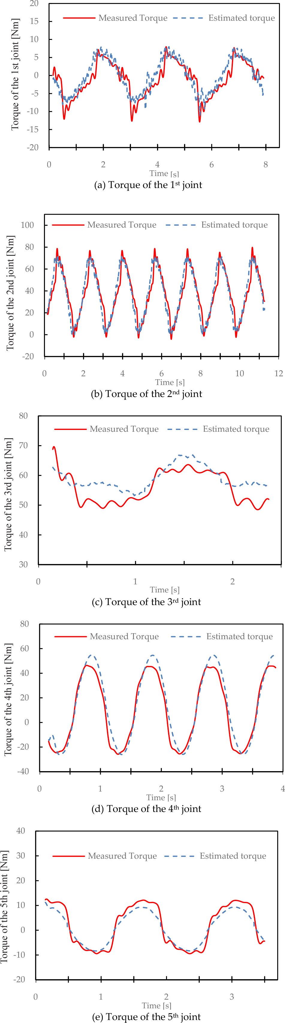
Comparison of the measured torque and the estimated torque for each joint

Kraft GRIPS hydraulic telemanipulator.

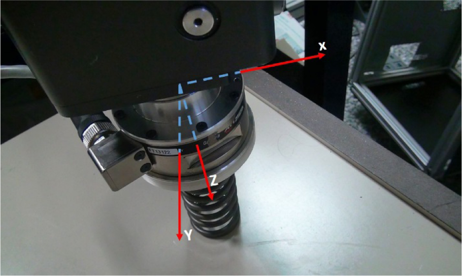
Manipulator reference system
Reference system of the force sensor on Kraft performing an elastic impact
Maximum and minimum excitation frequencies during the identification

From Table 2, it can be observed that the torque error is relatively small in comparison with the torque value.
Comparison of the root mean square residuals of the torque estimation

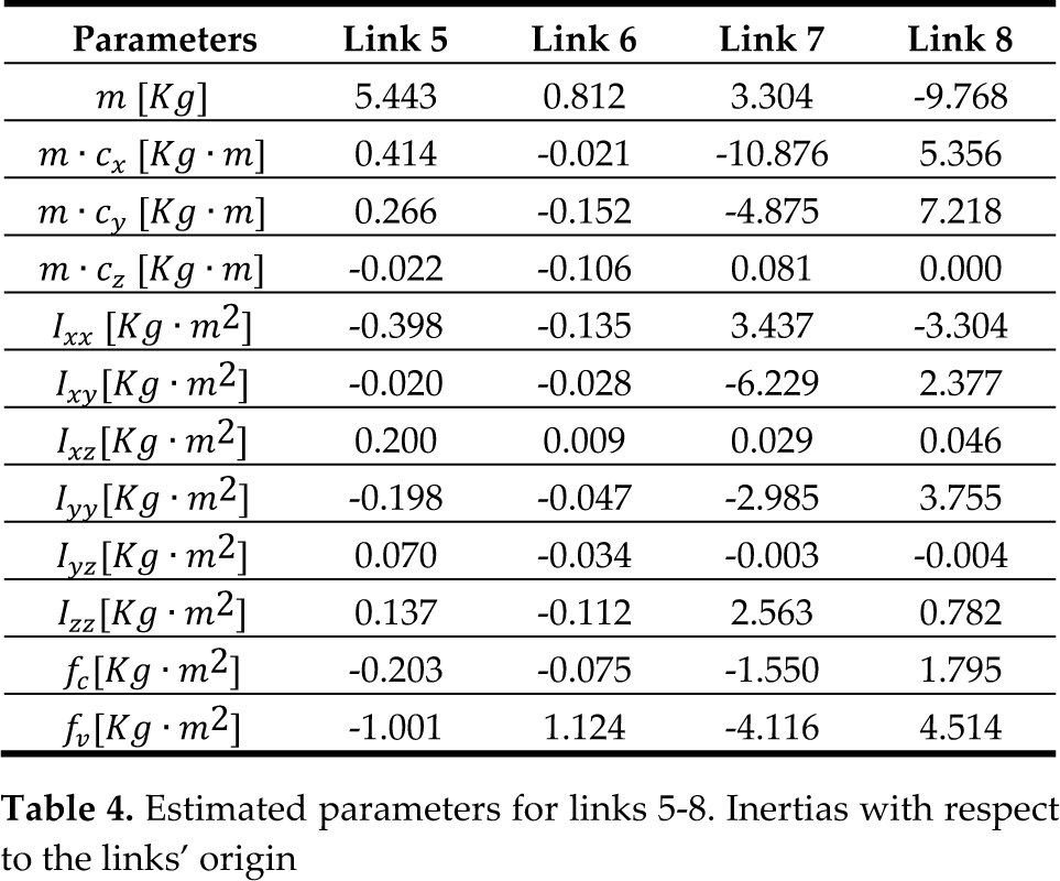
In Table 3 and Table 4, the 12 estimated parameters per link are presented. These are the mass m, the mass moment coordinates m · c i , the six components of the inertia tensor and the coefficients of the linearized friction equation for each link f c and f v . Eight links are presented, starting from the base to the end-effector. Link 7 is the tie bar parallel to link 2, while link 8 represents the small coupling between the tie bar and the SE joint. In a multilink robot, some parameters can only be identified in linear combinations, unless a torque sensor is placed on each joint. In a predictive model - as proposed - the LMS resolve the linear combinations in a pure mathematical approach, which make these inertial parameters appear different from the reality (or else as lacking any physical meaning).
Estimated parameters for links 1-4. Inertias with respect to the links' origin

Estimated parameters for links 5-8. Inertias with respect to the links' origin
5.2 Validation experiment
To verify the proposed method, the identification procedure was implemented in the described robot on the first five DOFs. Two different conditions were selected in order to reproduce the real efforts performed by the robot during a remote handling operation [44]. These are: the estimation of an elastic impact, and the estimation of a sliding effort.
5.2.1 Estimation of an elastic impact
An elastic interface was attached to the robot end-effector, with an ATI force sensor between them, in order to verify the effectiveness of the proposed approach. The robot was commanded to a pose with the end-effector approximately perpendicular to a horizontal plane. An up-down movement was accomplished, compressing the elastic interface by commanding joint 2, while the PID controllers of each joint maintained the other joints' positions. Figure 5 presents the results of the proposed method, comparing the estimated torque for the given dynamics with the real torque exerted on the actuators. The external torque has been calculated by subtracting the estimated torque from the measured torque. During the compression effort, the model only sees the movement accomplished by the robot (i.e., the inner torque), while the measured torque takes into account the real effort exerted. During this test, the main effort was realized by joints 2, 3 and 4, while the nonzero torque in joint 1 is explained due the incompletely perpendicular pose of the end-effector during the compression effort, which produces a tangential force on the contact point supported by this joint.

Model validation during the perception of an elastic effort. Three torques are compared in this figure: the measured torque which corresponds to the torque ejected by the hydraulic actuators; the estimated torque which is the model output to satisfy the dynamic conditions; and the external torque calculated by the difference of the former two
The external torques presented in Figure 5 were estimated by employing equation (18), below, which results from the reorganization of (1). As such, the external torque on each joint can be understood as the disturbance produced by the environment, which keeps the manipulator off from the estimated position on a free space movement. Thus, the estimated torque and motor torque will only match in the case of an absence of external forces and torques:

Figure 6 represents the external forces produced by the external torques mentioned earlier. Unfortunately, the only way to validate the results without incorporating a torque sensor on each joint is by means of a sensor attached on the robotic tip. This situation adds complexity to the model's validation, since the effects of several joints will be joined and amplified by the manipulator Jacobian. The analysis of the graphs shows the precision acquired by using this scheme, whereby the measured torque matches the estimated torque when in a steady state, and only when the manipulator exerts effort the external torque is non-zero.

External forces comparison on the z-axis.
Inaccuracies in the estimation of the joints' torque constant described in (3) also affect the force calculation. Nevertheless, the force slope exhibits highly linear behaviour characteristic of the springs, which is well-tracked by the estimator. The average relative error with respect to the force peak after applying the Jacobian transformation is 12.98%, which illustrates the precision acquired with this scheme.
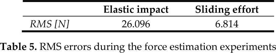
Table 5 compares the RMS error during the two validation experiments carried out for this paper. The graph in Figure 6 shows the torque-force conversion after applying the Jacobian transpose and inverse. This figure represents the main effort during the spring compression situated along the perpendicular line or z-axis.
RMS errors during the force estimation experiments
5.2.2 Estimation of a sliding effort
This test involves a sliding and horizontal movement on a rough, foam-type surface. For this experiment, no interface was attached on the end-effector apart from the force sensor used for validation purposes. The main sliding effort is carried out by joint 1, while joints 2 and 3 provide the gravity compensation torque. For the force estimation in this experiment, several additional difficulties were identified. Firstly, the small magnitude of the forces involved decreases the signal-to-noise ratio. Secondly, the adherence provoked by the high friction surface augments the contribution of the non-linear frictional effects not included in the simplified friction model. In Figure 10, the velocity profile of joint 1 is presented - corresponding to the torques and forces of Figure 8 and Figure 9, respectively - in order to check the influence of the Coulomb term of the friction.

Reference system of the force sensor on Kraft performing a sliding effort.

Model validation during the perception of a sliding effort

External force comparison on the x-axis
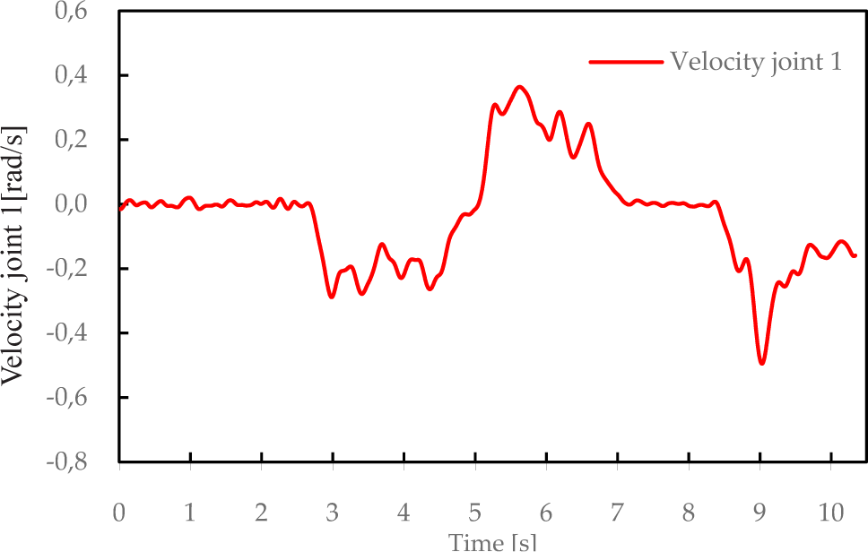
Velocity profile of joint 1 during the sliding movement
An additional effect was identified as a cause of added frictional errors during the movement of joint 1, since it was not possible to completely eliminate the effect of the hoses attached to the manipulator's back. In contrast to most electrical-based industrial robots, the movement of the Kraft GRIPS manipulator drags the hydraulic hoses as it moves, inducing an undesirable effect. Nevertheless, the results presented achieve good performance even in the presence of non-linear effects.
6. Conclusion
Facilities where maintainability and surveying tasks need to be executed in a hazardous environment will likely increase the application of remote handling solutions due to safety measures. Force feedback will be essential in performing remote handling and maintenance in these scenarios. Since back-drivable slaves and torque sensors are not always suitable or feasible, an alternative approach has been proposed which estimates the external forces and torques with an acceptable level of accuracy by using a robot model and pressure information. This approach was tested on a closed-loop hydraulic manipulator by means of estimating the disturbance torque based on the manipulator's dynamic equation with identified parameters. A loop closure function was applied to the observation matrix in order to accurately model the parallel tie bar and estimate the parameters of the eight robotic links.
The validation of the identification trajectories has been presented together with two different experiments emulating common efforts during a telemanipulation procedure. This method does not require any modification of the robot nor any additional wiring, but only the sensing of the proprioceptive conditions.
It can be employed not only as a substitute for conventional sensors but also as a redundant solution when other methods are preferred. In addition, this methodology can also be used as an earlier step when using observers, as in [33], where an accurate model of the manipulator is needed.
The applications of the proposed method are not limited to hazardous facilities but can also be applied to robot solutions where it is difficult to add a sensor to the end-effector - such as medical telesurgery - and where there is a need to design environmental- and size-specific force sensors. Also, this scheme is likely to produce a more cost effective solution and thus be more affordable in several different situations, such as de-mining, bomb disposal and burning buildings.
7. Acknowledgments
This research has been supported by a Marie Curie Early Stage Initial Training Network Fellowship under the European Community's Seventh Framework Programme, contract number PITN-GA-2010-264336-PURESAFE. This work has also been partially supported by the TeleScale project (DPI2012-32509), funded by the Spanish “Ministerio de Economía y Competitividad”.