
Abstract
Mobile manipulators are one of the most complicated types of mechatronics systems. The performance of these robots in performing complex manipulation tasks is highly correlated with the synchronization and integration of their low-level components. This paper discusses in detail the mechatronics design of a four wheel steered mobile manipulator. It presents the manipulator's mechanical structure and electrical interfaces, designs low-level software architecture based on embedded PC-based controls, and proposes a systematic solution based on code generation products of MATLAB and Simulink. The remote development environment described here is used to develop real-time controller software and modules for the mobile manipulator under a POSIX-compliant, real-time Linux operating system. Our approach enables developers to reliably design controller modules that meet the hard real-time constraints of the entire low-level system architecture. Moreover, it provides a systematic framework for the development and integration of hardware devices with various communication mediums and protocols, which facilitates the development and integration process of the software controller.
1. Introduction
A mobile manipulator refers to a robotic manipulator arm mounted on a mobile base. Mobility provides the manipulator with an unlimited workspace at the expense of added challenges[1, 2]. i Moro, shown in Figure 1, is a four wheel independently steered (4WS) mobile manipulator that is under investigation for high maneuverability and flexibility in high-speed motions under the PURESAFE project. The PURESAFE project, “Preventing hUman intervention for incREased SAfety in inFrastructures Emitting ionizing radiation”, was initiated to advance theoretical and experimental knowledge on semi-autonomous mobile manipulation within the ionizing radiation-filled and contaminated environments of accelerators, particularly within tunnels inside the European Organization for Nuclear Research (CERN).

Mobile platform of i Moro
A mobile manipulator is a complex mechatronics system that synergistically blends multidisciplinary solutions and methods from mechanics and embedded control systems [3, 4]. There are different issues associated with the development of such mechatronic systems, especially in the low level architectures involving device drivers and system controllers. One example of such an issue is that of interfacing with hardware devices, including different communication mediums and protocols. Moreover, developing mechatronic systems requires numerous and consecutive practical tests in order to verify and validate the functionality and integrity of the developed algorithms and codes. Ultimately, it should lead to an optimized implementation of controllers that can punctually receive sensor data and produce control signals over guaranteed intervals of time.
This paper is the synergistic conclusion of the authors' research on this topic, presented in [5, 6]. It demonstrates how the framework proposed in [5] for rapid prototyping of real-time controllers successfully provides a software development basis for the i Moro mobile manipulator, the design of which is presented in [6]. In the following, the authors present the background study for the hardware and software architecture and introduce the integration approach. Section 2 details the hardware design of the mobile manipulator and discusses the selected communication interfaces between the components. Section 3 explains the framework for the real-time software integration. The final section presents the experimental results of successful implementation of the method.
1.1 Hardware Architecture
The main challenge in designing a mobile manipulator is the selection of its mobile base and wheel configurations. Wheeled mobile robots with different drive-steering mechanisms have been researched and engineered [7]. The most common variation is that of the differential drive robot. These have minimal actuated degrees of freedom and no moving parts for steering [8]. The second most popular mechanisms, particularly for office environments, use omni-directional wheels such as the Mechanum or Swedish wheels [9, 10]. Such mechanisms provide freedom to control robot heading independent of linear translation, thus increasing maneuverability. They also use a differential drive for steering. However, as mentioned by [11], a large portion of the tangential force is lost by the rolling parts. Therefore, these types of robots often have high maneuverability but lower efficiency, which is an important factor in a battery-powered mobile platform [12].
For years, differential-type mechanisms have been popular due to the simplicity of their mechanics; however, 4WS mechanisms have recently received increasing attention as suitable platforms for mobile manipulators. 4WS mechanisms enhance the functionality of normal wheels for smooth motion, efficiency, and maneuverability for indoor applications [13]. Off-road applications of 4WS robots have been reviewed by [14]. The drawback of the 4WS design is the increased complexity of its mechanics, kinematics, and control in both autonomous and manual modes [15, 16].
Many studies have attempted to simplify motion control and synchronization of actuators by mechanically constraining steering angles (by implementing steering mechanisms, such as in [17, 18]) or by employing control strategies that keep the wheels parallel to one another (as in [19]). These solutions can solve conventional over-steering or under-steering problems of car-like robots, but they also decrease robot maneuverability. An efficient solution that enables the robot to maneuver in limited space requires independent steering of each wheel [13, 19].
1.2 Software Architecture
Another challenge in the process of designing a mobile manipulator is the selection of a suitable software development framework for the robot. While software engineers prefer direct C\C++ programming, control engineers and system developers prefer MATLAB and Simulink or similar software or toolboxes because of their ready-to-use advanced mathematical functions and algorithms. Additionally, in most cases, the simulation of the control algorithms is done in MATLAB/Simulink, and re-implementation in C\C++ is both time consuming and a potential source of errors. However, the high-level programming of this approach makes the models developed in MATLAB/Simulink unsuitable for real-time tasks.
On one hand, during the design procedures of a complex mechatronic system, several teams of researchers are working simultaneously on the design processes and modeling of both hardware and software platforms. Thus, even conceptual design and development of product hardware can be subject to change at the same time that software is being designed. On the other hand, validation of the developed design models, methods, and tools occurs through prototype experiments. The desirable outcome benefits the blocks, modules, and patterns of the implemented components and written software, which can be reused. Therefore, a real-time control rapid prototyping environment is necessary to overcome the control issues of a mechatronic system and simultaneously consider other criteria, such as modularity, flexibility, reusability, compatibility with commercial off-the-shelf components, and creating a dependable basis for future advances in safety measures (such as the Safety Integrity Level (SIL)).
Several studies have examined the real-time implementation of algorithms in MATLAB [20, 21] and its integration with Linux [22]. Moreover, there are available software package applications that utilize selected functionalities of MATLAB in their real-time execution environments, such as the xPC Targeting toolbox [23], RT-Lab [24], and RTAI-Lab [25]. Mathworks has addressed this problem by embedding code generator products that automatically generate optimized, independent, and royalty-free C\C++ code from MATLAB codes and Simulink models. Comparing generated C\C++ codes with their original MATLAB codes is the subject of research in [26].
Generally speaking, one of the challenges in a mechatronic system is making interfaces that are operational between real-world sensors and actuators and the software that develops computational controllers like MATLAB. This challenge has been solved in dSpace® products by means of the complementary hardware for rapid prototyping and code generation in its package, which has been used in several research studies [27]. The RTAI Linux team [28] has also produced a comprehensive work that integrates RTAI-Lab into Simulink and translates the code into the RTAI framework by means of Real-Time Workshop (RTW). These systems are popular for a certain range of control and software requirements. However, compared to traditional C\C++ software development, their solutions enforce additional limitations on the reusability of existing codes. This problem is negligible until research and development teams use products that are only compatible with their development environments. In the event of any unforeseen instrumental necessities, adaptation of a third-party driver to those environments is full of difficulties. On the other hand, a normal C\C++ application can easily use manufacturer-provided drivers for C\C++.
1.3 Integration
This paper discusses a software development environment for the rapid prototyping of the afore-mentioned mechatronic systems. Its aim is to introduce a coherent framework for remote development of independent hard, real-time software controllers based on MATLAB and Simulink products for the rapid prototyping of PC-based mechatronic systems. The authors provide the technical details of the method in [5]. This paper shows how the method is successfully applied to the i Moro. The proposed method consists of developing software modules and controllers in a Simulink project on a PC with a Windows operating system, with a target of one or several embedded PCs running real-time Linux (the “Target PC”). Then, the Code Generators toolbox is used to derive a stand-alone and hard real-time C\C++ code for the real-time Linux operating system. The resultant code is automatically transferred to the embedded target, where it is compiled and built. The final software is ready to debug, run, or verify on the Target PC.
Note that this methodology could easily be expanded to develop multiple software programs to run on the Target PC at once. For very complex mechatronic systems, in which software and controllers cannot be put into one executable application, this method could be used simultaneously for multiple Simulink models to develop different parts of the whole software. Then, each model could be turned into a module or service on the Target PC and collaborate with other modules by means of different internal communication services, such as programming queues. Hence, developers would be able to benefit from Service Oriented Architecture (SOA) principles [29] in developing their software. Furthermore, the code can be generated not just for Windows, but also for a wide variety of operating systems that support the Portable Operating System Interface (POSIX) [30].
Moreover, this paper addresses some of the issues and difficulties commonly associated with remote development and code generation with MATLAB and Simulink products. One of the main issues is how to integrate device drivers and hardware interfaces into Simulink models. Technically, these interfaces should be turned into re-usable Simulink block libraries. However, the drivers and their related API libraries are installed differently on the remote target system (real-time Linux) than on the operating system of the development environment (Windows®) Hence, deriving such blocks demands more advanced treatment. Addressing this issue requires detailed knowledge of S-Function programming as well as the development of Target Language Compiler (TLC) files that tell code generators how to generate C code out of the S-Functions.
2. Robot Architecture Design
This section details the primary design requirements. We have documented a comprehensive list of the requirements in [31]. The i Moro mobile manipulator is designed based on this list. In this section, different components of the mobile platform are presented, and their physical and logical architecture and designed interfaces are explained. Moreover, the implemented embedded controller that facilitates rapid prototyping of the controller software is described. Finally, we explain different implemented control modules designed for performing tele-operation and autonomous tasks. A high-level state machine controller is devised that governs the execution order of the controller modules.
2.1 Design Requirements
As mentioned before, the main aim of the PURESAFE project is to design a mobile manipulator that can be utilized to perform inspection and manipulation tasks in hazardous environments of research facilities. Here, our main focus is to design a mobile base and manipulator for such a robot. Below are the key requirements considered in the design of the mobile manipulator:
The mobile platform should be able to carry 30 kg of extra load. The mobile platform should be able to pass through normal doors. The mobile platform should have high maneuverability that enables it to rotate and changes its heading in limited spaces. The whole system should be able to perform operations for at least several hours and travel two to three kilometers without recharging. The hardware and software of the whole system should be component-oriented and modular to allow the simultaneous development of different components. The software platform for the controller should support real-time capabilities while providing simple and straightforward means to develop and test different software modules. The designed control modules should provide both autonomous and tele-operated capabilities for the mobile platform. The manipulator should be able to handle a weight of 10kg The manipulator should have a gripper capable of grasping a cube with a section size of 10cm × 10cm The end-effector of the manipulator should have dexterous motion up to a height of 1.2m outside of the moving platform.
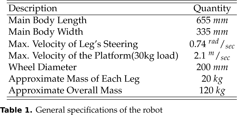
Some trade-offs among these requirements are necessary in order to maximize the stability of the platform, especially during manipulation tasks. For example, it is desirable to make the platform's size as large as possible. However, the second and third requirements limit the size of the platform. Thus, we consider the maximum dimensions that satisfy those requirements for the overall size of the base. Table 1 lists specific parameters of the mobile platform.
General specifications of the robot
The third requirement presented in 2.1 requires the platform to perform pure rotations. More generally, in order to achieve high maneuverability, the robot should have a decoupled heading and linear movement or, in other words, three degrees of freedom for the main body. As mentioned before, there are two popular types of architectures for mobile robots that hold such characteristics. The first type is the differential drive mobile robot, which has at least three omnidirectional wheels, such as the one presented in [9]. The second type is the pseudo-omnidirectional mobile robot, which has at least two wheels with independent steering and driving actuators . The efficiency of omnidirectional wheels is minimal, hence, such wheels limit the general efficiency of the robot. Moreover, such robots must carry relatively smaller payloads. Based on the payload and efficiency requirements, we designed the mobile platform based on the second popular robot architecture.
2.2 General Design
The designed platform consists of four wheel modules (legs). Each leg has two degrees of freedom for independent driving and steering. Figure 2(a) portrays the designed leg, which consists of two parts: a moving part and a fixed part. The fixed part contains the actuators and their directly connected gearboxes. The steering motor rotates the entire moving part along the vertical axis of the leg. Since there are no mechanical constraints, the moving part is able to rotate multiple turns . The first driving gearbox is connected to the second one via a shaft that passes through the steering gear box. The second driving gear box then rotates a pulley-belt system connected to the wheel.
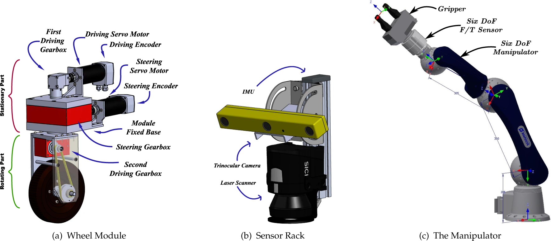
Designed Modules
All the actuators are driven by the same motor type (brushless servo motor, 400 watt). Based on the selected motors and other mechanical components, the nominal efficiency of each modular wheel at a speed of 1.7m/sec is 70%. The motors are derived using Maxon EPOS2 drivers, which support different control schemes such as position, velocity, and torque based on CiA CANopen® specifications [32]. The drivers for the steering actuators are configured to work in position mode and to return the position as feedback. On the other hand, the drivers for the driving actuators receive and execute velocity commands while their desired feedback is configured as the speed of the motor.
The main sensors that are used for localization and navigation (except actuators' encoders) are assembled on an external body called the sensor rack. It contains a laser range finder, a stereo camera, and an Inertial Measurement Unit (IMU). Figure 2(b) illustrates the designed sensor rack. As shown in the figure, the camera's field of view and the laser scanner's vertical position can be adjusted at will during the development phase. The main advantage of such a design is that it turns the whole system into an individual module for localization and navigation that can be easily attached or detached from the base. Such a modular design also facilitates the calibration of the sensors with respect to one other. Moreover, it allows the developers to work separately on the module and the mobile platform during development, while the mobile robot can undergo independent developments before the integration phase.
Last but not least, the schematic view of the selected manipulator for the i Moro is shown in Figure 2(c). The whole arm contains six DoF manipulators that are connected with six DOF Force/Torque sensors to a double finger gripper. These components are off-the-shelf products. The main challenge here is the synchronized interfacing of these components with the rest of the mobile platform devices, a topic that is thoroughly discussed in the next section.
2.3 Communication Interfaces
This section presents the selected communication interfaces for the i Moro. As described in the next subsection, a fanless embedded PC is used as the controller hardware. Sensors and actuator drivers are connected to the controller via various communication interfaces. The schematics are shown in Figure 3.

Communication Interfaces of various components
Figure 3 illustrates that there are four CAN networks in the system. The communication speed of each network is 1 Mbps. The devices connected to each network are selected in such a way as to minimize potential conflicts and maximize communication frequency. For example, the manipulator force feedback is the fastest loop in the system and should be closed with the frequency of 1KHz. Hence, an entire network is dedicated to the force/torque sensor module to facilitate such a high sample rate. Moreover, since the drivers of the wheel actuators communicate via a similar CANopen 1 protocol, another CAN network is dedicated exclusively to them. The network implements the CANopen Heartbeat protocol to continuously monitor the status of the devices. All the devices expect to receive a Heartbeat message from the embedded PC every 50ms and to send Heartbeat messages to the embedded PC every 100ms. The controller sends desired set points to the drivers every 10 ms using Process Data Objects (PDO). The system implements the CANopen Sync protocol in order to synchronize the actuators.
2.4 Embedded Controller
The robot is equipped with an embedded PC that acts as a central controller for the whole mobile platform. Since the robot will need to operate in contaminated areas, the authors have selected a fanless embedded PC with powerful cooling. The PC's quad-core CPU is capable of running multiple software modules, such as vision and motion control, in parallel. Hence, it provides a powerful computational base for executing complex algorithms. Some communications require prompt responses to the data received from sensors or must send the commands at exact time intervals. Therefore, the software platform must provide hard real-time capabilities for some interfacing software modules.
The authors use Xenomai 2 real-time Linux as the Operating System (OS) for the embedded PC in order to provide such real-time capabilities. However, it is impossible to execute all the software modules in the hard real-time environment due to the non-real-time nature of some of the software functions. This is the case especially for some interfacing modules, such as User Datagram Protocol (UDP) packets and almost all other LAN network protocols that are not generally supported in real-time environment.
Here, the authors use a multi-thread programming approach. Different software modules of the controller are executed in different executing threads. Hence, modules can be run in the hard real-time scheduler of the OS or the non-real-time scheduler, depending on their characteristics. Real-time programming queues are used to communicate between different software modules.
The communication interface for the CANopen network is implemented using the Xenomai RTDM library, which is executed in hard real-time environment. This is also the case for gathering data from the laser range finder through LAN using the RTnet real-time library. However, the process of capturing images from the stereo camera or UDP communication through the wireless network is executed in a non-real-time environment. The implementation of such a strategy can be quite tedious and time consuming, especially in the development phase, when software modules and algorithms subject to constant change and improvement. In order to facilitate rapid prototyping of different algorithms and software modules, especially in real-time environments, the authors implement a unified framework that was initially proposed by the authors in [5]. This framework is presented in the next section.
3. Development Environment for the Controller Software
This section provides a general description of the proposed framework for the rapid prototyping of a PC-based mechatronic system such as a mobile manipulator. The framework allows developers to develop their control software in Simulink and to use MATLAB code generation products to automatically generate and build real-time code for their control modules. The whole system is divided into three distinct environments, which are shown schematically in Figure 4. The Development Environment consists of tools that are used to develop the controller and generates the pertinent C code for the whole software. The Target Environment consists of the actual mechatronic system, which receives the generated code and compiles it into the real-time software. The Supervisory System sends runtime commands to the mechatronic system and generally receives monitoring data and information. Both the Development Environment and the Supervisory System can be run on the same machine. Detailed descriptions of each part are given in the following sections.

Schematic Diagram of the Rapid Prototyping Framework
3.1 Remote Development Environment
The development environment consists of a Windows PC with MATLAB and Simulink installed (the “Host PC”). The Host PC is connected to the Target PC responsible for controlling the mechatronic system by means of a LAN network. The model for the whole software controller is developed on this system as one or more Simulink models. An SSH connection is used to transfer data between the Host PC and the embedded real-time target. Hence, the Target PC should be configured to accept SSH connections. Moreover, the PuTTY 3 SSH software should be installed on the Host PC. MATLAB uses this software to establish a RSH connection to the Target PC and to transfer the generated code. Note that, prior to MATLAB 2011a, the code generation packages were called Real-Time Workshop and Embedded Real-Time Workshop. Since MATLAB 2011a, these packages have been combined with related packages and are now presented as three products called Matlab Coder, Simulink Coder and Embedded Coder. The reader is referred to MATLAB documentation for further information. The terminologies used in this paper are based on new versions of MATLAB. Those packages have their own licenses and should be installed with MATLAB.
The controller and computational algorithms for the mechatronic system are developed as a Simulink model and can be tested with simulation tools in Simulink before being sent to the actual system. Since the 2011 release, Simulink has added a new Project feature, which has useful properties such as Subversion® source control. Project can be utilized to manage a highly complex controller in a collaborative environment. Once the design evolves to an acceptable level of maturity, generated blocks for device drivers will be added to the model and appropriate signal connections will be set between those blocks and the developed software. Note that some of the blocks in Simulink support only a specific operating system. Although the Simulink model is being developed under Windows, networking blocks such as UDP have both Windows and Linux versions. Since the target system is Linux-based, the model should use the Linux versions of such blocks.
The model requires specific configurations to allow the code generator to produce appropriate code for the Linux target. Once these configurations are made, the Embedded Coder is used to generate C code for the whole Simulink model. Along with generating code, the Embedded Coder is configured to generate the Makefile for the produced code with appropriate paths and flags. The Makefile is based on set of configurable templates. However, it is made for the Host PC which means that, although the libraries used in the generated code are designed for Linux, the paths and flags associated with them are related to the MATLAB installed folder in the Host PC. Hence, the Makefile is useless in the Target PC.
Nevertheless, a useful MATLAB function called remoteBuild can be used to solve this issue. remoteBuild receives as input an object called buildlnfo, which is a by-product of the code generation process, along with information on the Target PC such as its IP address and user credentials. First, the remoteBuild function reads the produced Makefile, gathers all the headers and libraries based on their Makefile paths, and adds them into an archived folder along with the generated code. Then, the function modifies the Makefile and produces another with appropriate paths and flags, which it adds to the archive as well. Next, it establishes an RSH connection with the Target PC and extracts the archive there. Finally, the make command is used to compile and build the software executable on the Target PC. Note that this entire process is done automatically. Further notes on the configurations that should be made in the Simulink model for using remoteBuild are given in [5]. Note that the executable application made on the Target PC is fully independent of MATLAB, the Host PC, or any other part of development environment. Hence, the entire environment can be disconnected from the embedded real-time target.
3.2 Embedded Real-Time Target
The real-time target consists of an embedded PC running a real-time Linux operating system. It is connected to hardware devices by means of different communication networks and protocols, such as Serial, USB, CAN, etc. It is assumed that device drivers and software libraries associated with those devices are properly installed on the Target PC. As mentioned before, the execution of the remoteBuild function copies the generated code, along with the Makefile and other dependencies, to a specified path in the real-time Linux system. remoteBuild uses a GNU compiler to compile and build the code into executable software. Once the software is run, it can receive runtime commands from the supervisory system and send logging data and monitoring information in return.
3.3 Supervisory System
As mentioned before, the Supervisory System is in fact the operator station and is used to send runtime commands and receive monitoring data from the Target PC. Physically, it can be the Host PC, the Target PC, or a fully separate system that is connected to the Target by means of a computer network (more technically, through the sending and receiving of UDP packets). In advanced cases, it could contain HMI interfaces, virtual reality programs and task planners. Again, code generation products can be utilized for the development of such software.
4. Experimental Results
The proposed method was implemented on the i Moro mobile manipulator. The host PC connects to the department's wireless intranet via a Wi-Fi modem. It is accessible through the school network. Over this network, the embedded Target PC on the iMoro with Xenomai Linux is connected to the Host PC, which has MATLAB R2013a installed on it. The framework presented in this paper was used to develop a software controller for the robot. Several controller modules were developed in Simulink. The modules consist of systems for receiving tele-operation commands, obstacle direction using the laser scanner, differential driving, etc. In order to interface with hardware components, the authors implemented the approach discussed in the previous sections with the technical details given in [5].
The entire real-time software for the robot based on the methodology discussed in Section 3. The complete model was developed in Simulink. Then, the Embedded Coder toolbox was used to generate the code from the model, with the real-time Linux system defined as the target. The code was sent automatically to the Target PC and built by the GNU compiler. The software has a base thread with a real-time periodic sample time of 1e − 4 seconds. No calculations are done in the base thread. The thread is used as a trigger for activating slower periodic tasks that implement the control modules and device communications. The faster periodic tasks have a sample time of 1e − 3 seconds and close the force/torque feedback loop of the manipulator's F/T sensor. The main periodic tasks have a sample time of 1e − 2 seconds and run the low-level control algorithms for both the wheels and the manipulator actuators. This arrangement guaranties synchronization between the actuators of the arm and the mobile base.
To show the accuracy of the synchronization between the actuators, we present some results of a sample experiment with the mobile platform. In this example, the platform is required to follow a desired curve and the synchronization error between the wheel-driving actuators is recorded. The path followed by the mobile platform is a cubic Bezier curve with its control points located at (0,0), (2m, 0), (2m, 2m), (0, 2m) . The platform's desired heading profile changes from 0 to 180°. Figure 5(a) shows the body and leg trajectories following the given profile. It also depicts as red dots the estimated location of the body's Instantaneous Centre of Rotation (ICR) during its movement. Figure 5(b) renders the norm of the synchronization error between the wheel-driving actuators. From the figure, it is clear that, due to real-time synchronization of the set points, the velocity error between the actuators is far less than the medium of the actuators' speed, which is 100mm/sec. In the event that the wheel odometer feedback is used to localize the base, this error can be further reduced by using the redundancy in the number of the mobile base actuators. We have presented the details for such treatment in [6].

Experiment: (a) Mobile Platfrom Follows a half-circle trajectory and change its heading 180°. (b) The norm of synchronization error between the wheels' driving actuators.
5. Conclusion
In this paper, we present the mechatronics design of the iMoro mobile manipulator. We discuss the low-level software architecture based on embedded PC-based controls and present a systematic solution based on code generation products of MATLAB and Simulink. We The authors propose a simplified solution for rapid prototyping of the controller software in the hard real-time Linux environment that significantly reduces the complexities often arises in the design and implementation of low- level real-time controllers. The proposed framework allows the developers to easily synchronize the collection of various sensor data and actuator commands, that notably increases the performance of the mobile manipulator.
6. Acknowledgement
This work, supported by the European Union's Seventh Framework Program under the Marie Curie Initial Training Network, was carried out within the framework of the PURESAFE, Preventing hUman intervention for incREased SAfety in inFrastructures Emitting ionizing radiation, under REA Grant Agreement Number 264336.