
Abstract
This paper describes how a building information modelling (BIM)-based approach for building circulation enables us to change the process of building design in terms of its computational representation and processes, focusing on the conceptual modelling and representation of circulation within buildings. BIM has been designed for use by several BIM authoring tools, in particular with the widely known interoperable industry foundation classes (IFCs), which follow an object-oriented data modelling methodology. Advances in BIM authoring tools, using space objects and their relations defined in an IFC's schema, have made it possible to model, visualize and analyse circulation within buildings prior to their construction. Agent-based circulation has long been an interdisciplinary topic of research across several areas, including design computing, computer science, architectural morphology, human behaviour and environmental psychology. Such conventional approaches to building circulation are centred on navigational knowledge about built environments, and represent specific circulation paths and regulations. This paper, however, places emphasis on the use of ‘space objects’ in BIM-enabled design processes rather than on circulation agents, the latter of which are not defined in the IFCs' schemas. By introducing and reviewing some associated research and projects, this paper also surveys how such a circulation representation is applicable to the analysis of building circulation-related rules.
Keywords
1. Introduction
Building information modelling (BIM) has impacted broadly on the architecture, engineering, construction and facility management (AEC-FM) industries and their associated work processes. BIM can be regarded as a ‘process’ because it designates the holistic environment required and the informational technology applied to produce, maintain, control and apply BIM throughout the entire building lifecycle. Experiences, lessons learned and improvements made have been actively shared and discussed through various industry- and government-driven BIM projects, whether completed or in progress [1, 2]. From the perspective of BIM-enabled building design, it has been designed for use by several BIM authoring tools, in particular the widely known interoperable industry foundation classes (IFCs), which follow an object-oriented data modelling methodology. Advances in BIM authoring tools have made it possible to model and visualize circulation within buildings in an automated way prior to construction, by using space objects and their relations defined in IFC schemes [1, 4].
Among the various applications of BIM, this paper points out how architectural design could be improved by BIM, placing emphasis on the use of ‘space objects’ in the BIM-enabled design process. One of the biggest methodological differences in using the BIM process in place of the conventional CAD (computer-aided design) process in architectural design is the shift from ‘geometric shape design’ to ‘information modelling’ [3]. The term ‘information’, here, obviously includes geometric shape data, usually in three-dimensional forms. As shown in Figure 1, the difference is more clearly specified when the building information is subdivided according to the perspective of modelling a ‘building object’ and its ‘properties’ [3, 5]. Figure 1 also illustrates how BIM has facilitated the modelling and representation of building circulation within buildings, thanks to rich information defined in a given BIM model. The group of ‘rectangular shapes’ in a conventional computer-aided design and drafting (CADD) model does not have any circulation-related data per se, while ‘space objects’ have their topological connections as a fundamental data source of the spatial network. In this paper, we tackle circulation issues enabled by ‘space objects’ in a BIM model, rather than conventional CAD-based circulation analysis or visualization. As one of the most important building objects, a space object delivers spatial information that is reusable in the building lifecycle, even in the early phase of design [6]. The relation between spaces is defined in the BIM model, and the adjacency data between spaces defined in the model is automatically generated. This dataset is the main source of information required to compute circulation within buildings.

A space object and its properties for BIM-enabled circulation modelling and representation: from a CADD model to a BIM model
Thus, in this paper, we use a BIM model when tackling the conceptual modelling and representation issues of circulation within buildings and their associated rules. This paper avoids solving a given specific problem or proposing a totally new finding that lies beyond the scope of the work. Also, this paper describes building circulation and elements within the scheme of IFC in the perspective of building objects; therefore, some entities that are not defined in IFC - such as pedestrians - have been ignored or substituted with space objects. However, this intrinsic limitation has contributed to the surveying of several former research and development projects partially conducted by the authors [2, 3, 5, 6, and 7], and to building the software-independent and generic approaches to the conceptual modelling and representation of building circulation. This paper has a potential impact on modelling such generalized concepts in order to develop further applications.
2. Background
2.1 Circulation within Buildings
In the AEC-FM field, the domain of building circulation modelling and its representation is of special interest to several participants. Architects and designers need to express their design intent using spatial planning programs; building owners and occupants need to foresee circulation patterns within buildings; and design evaluators need to assess building circulation according to intended circulation. In addition to some qualitative factors of circulation representation, we emphasize two aspects of circulation representation methods. The first is to explicitly describe the spatial topology of circulation between two spaces, and the second aspect is to denote measured walking distances in a precise manner. Obviously, many people involved in a building design project are familiar with conventional topological graphs on a building floor plan. For example, a bubble diagram for a space program denotes the adjacency of programmed spaces or zones in the early phase of design. It is a well-known topological graph, and one of the pragmatic, metric, graph-based approaches; its algorithm was developed by [7].
2.2 Circulation Research in a Spatial Morphology Area
Within the AEC-FM domain, access and the topology of spatial networks have their own fields of study, called ‘spatial morphology’ and ‘space syntax’. The general idea is that spaces can be broken down into components, analysed as networks of choices, and then represented as maps and graphs that describe the relative connectivity and integration of those spaces. This has since grown to become a tool used around the world in a variety of research projects and design applications in the fields of architecture, interior design, urban design, planning, transport, and so on. In general, the analysis uses one of the many software programs that allow researchers to analyse the graphs of one (or more) of the primary spatial components. In this paper, some of the interesting issues in space planning within buildings are tackled based on these related approaches and applications, but with the primary focus on the conceptual modelling and visualization of circulation. In addition, the ‘spatial component’ here means the space object defined in a given BIM model.
2.3 Graph and Information Visualization
The visualization of relational data is important, but more fundamental and critical in display efficiency is the way in which information is visually translated and encoded. The value of visualizing such data emanates from the fact that the perception of visual information and patterns is an enhanced intrinsic characteristic in people, as opposed to the exhaustive search for corresponding patterns in alphanumeric datasets. Graph theory-based visualization, as shown in Figure 2, is an example of the visualization of relational data that facilitates navigation through the visual representation of that data. It is an increasingly significant area of research that has been widely implemented in many applications in order to view large and complex networks.
Example representation of circulation paths using a graph structure where each node represents a space object
Palmer and Rock [8] demonstrated a basic aspect of node-link diagrams through an experiment. They introduced the gestalt principle of connectedness as a key issue that supersedes proximity, size, colour and shape, perceptually. People tend to perceive nodes that are linked by line drawings as belonging together, much more than nodes that are closer in proximity or share the same colour or shape. The results from this experiment strongly support the value of the node-link diagram -where edges are drawn as lines between nodes - as an effective method of representation.
3. Graph-based Circulation Representations
Graph theory is an effective way to manipulate and represent spatial problems in fundamental building design processes in order to visualize this kind of information. It should be noted that graph-based systems primarily have two simple, yet very different, approaches: 1) a building design process enhanced by graph theory, and 2) a graph theory-based analysis of predefined building designs. The former approach describes design-oriented examples, while the latter is mostly studied for developing building evacuation models in fire and egress conditions [9, 10]. Our subject here is the latter. We describe below an overview of the two approaches, and review the BIM-enabled graph generation and analysis of circulation.
3.1 Design-oriented Representations
Werner et al. [11] classify navigational knowledge using route graphs in terms of various agents. The graph-based approach to circulation and navigational knowledge has been acknowledged by many researchers because of its simplicity and efficiency. Architects use graphs in the form of freehand sketches, such as bubble diagrams, to represent space-to-space relationships in the early phase of design. Pioneering researchers seeking to adopt graph theory in space planning include Eastman [12, 13], who developed a graph theory-based system for floor plan generation in the early design phase, and Roth, who researched a method to convert adjacency graphs to a floor plan [14].
The previous systems represent information based on the topological relations within spaces in early concept design phases. Topologically represented graphs provide spatial adjacency and connectivity information. Precise metric information, such as area, volume or distance, is unsuited for representation by such topological graphs. This detailed geometrical data could be represented by a graph structure, mainly controlled by the designer's intentions. Hashimshony described this process as three phases of architectural design [15]: a programmatic phase, a topological phase and a geometrical phase.
3.2 Analysis-oriented Representations
We focus on a given building model, where graphs are generated based on the predefined geometry of the model rather than the prediction or observation of agents' movements. Literature from the architecture, environment and behaviour, space syntax, and spatial cognition areas provides insights on issues of interest, such as reflecting human behaviour in graph-based representations, as well as providing a basis for enhanced perceptual and cognitive aspects of graph visualization. Bafna introduced the visibility-based isovist and its applications [16], while Turner devised an algorithmic definition of the axial map for an isovist [17]. An isovist denotes the area visible from a given location in a floor plan, and its line-based representation is an axial map. We observe that people generally move from one place to another following these axial lines because they are visible paths, and they tend to walk following an easy and efficient path. In other words, the most ‘human-like’ walking trace will follow the shortest, easiest and most visible path(s). Calculating walking distances based on these path lines would provide more accuracy as well as better visualization. Accordingly, [7] has researched and implemented just such a metric graph-based circulation representation method. This is shown in Figure 3, which also includes other types of graph representations. This is one of the BIM-enabled circulation visualizations.
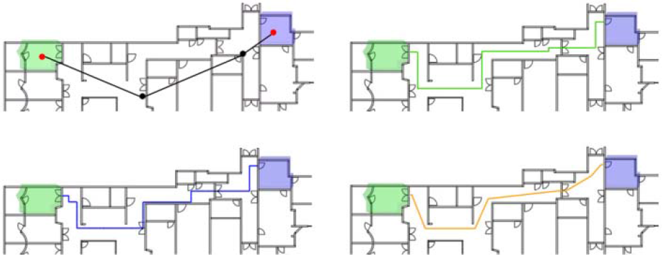
Various graph-based representations of circulation between two spaces. The bottom-right one shows the metric graph structure ([7], modified).
4. BIM-enabled Circulation Representation
4.1 Fundamental Specification of a Circulation Graph
There are several useful aspects of building circulation reflecting various of the representation methods and approaches reviewed in the former section. Given the fact that BIM models provide rich spatial and technical data for generating circulation information, we utilize the previously presented issues in order to informally describe specifications of BIM-enabled circulation graphs, as follows:
Building model-independent representation: the graph represents people movement paths in any given building model in a consistent way.
Building object-oriented representation: the graph represents a building model-centred circulation model, mostly determined by building design. Therefore, circulation factors should be considered (e.g., circulation rules defined in design guidelines) rather than a free agent-based circulation representation or simulation.
BIM-enabled representation: this inherits highly advanced privileges from the BIM-enabled features using a well-defined IFC.
Representation reflecting human behavioural factors: the graph represents the most frequently shown movement pattern of people; for example, people tend to take the shortest, easiest and most visible paths, as reviewed in the former sections.
4.2 Circulation Information derived from an IFC
Space information is required in order to handle a building's circulation issues. The space information can be represented by name, geometric shape, boundary walls and doors. A BIM-enabled design process allows architects to define this information explicitly. Lee [5] shows those objects and their properties according to four different criteria: basic (given) properties, relations, computed relations, and computed and derived properties. BIM tools utilize this data model to consider data sharing and the transferring of building information. Figure 4 provides an example of the description of the relationship between space and boundary design components in terms of the IFC schema. The IfcRelSpaceBoundary entity defines the physical or virtual delimiter of a space as its relationship to the surrounding building elements. The entity is defined as an objectified relationship that handles the element-to-space relationship by objectifying the relationship between an element (IfcElement) and the space (IfcSpace) it bounds.

Simplified diagram illustrating how IFC data contains a spatial topology: The IfcRelSpaceBoundary entity defines relational information between spaces
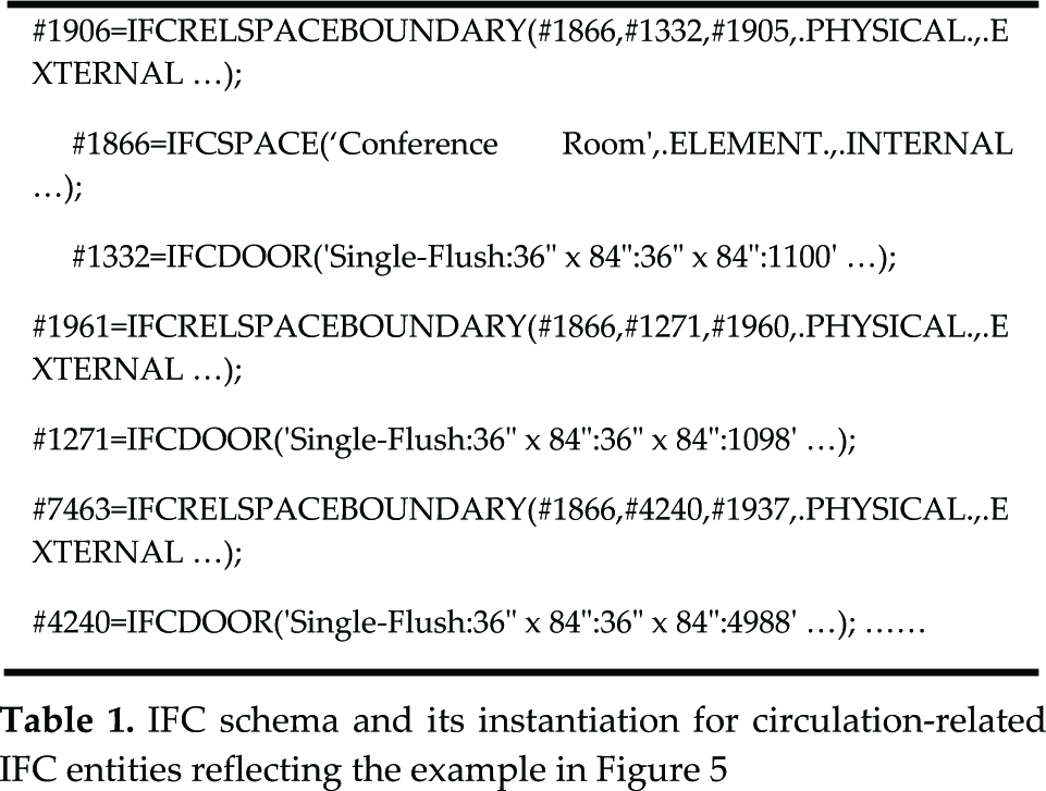
As shown in a simple example model in Figure 5, a space called ‘Conference Room’ is enclosed by four walls and three doors. This example is represented as physical data in Table 1. It shows a physical file format based on ISO/STEP Part 21 [18, 19]. The physical data can provide information about space and boundary elements, and also spatial connectivity data - that is, how a space is adjacent to other spaces - in order to retrieve a spatial topology.
IFC schema and its instantiation for circulation-related IFC entities reflecting the example in Figure 5

An example of the entity “IfcRelSpaceBoundary” and related entities
5. Conceptual Modelling of Circulation
5.1 Definition of Circulation
Inter-space circulation simply means a state of movement from a particular space to another. All these spaces are in a building - that is, within a built environment - and they are defined by users utilizing space objects in the BIM-authoring tools. A route is a concatenation of directed Route Segments from one place to another [11]. A route segment consists of two spaces - a start and a target space - which are connected by a path. Mathematically, the number of traversal types in general for all paths between two nodes is infinite in number. In this paper, all paths P are reduced to closed sub-paths P′ and other iterated paths P″. A path has no repeated edges or vertices.
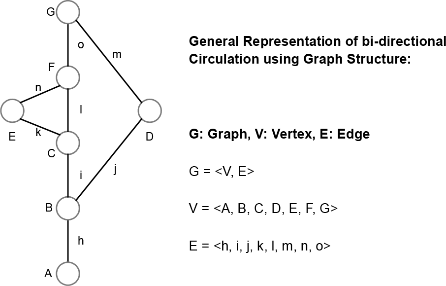
Using spatial topology data defined in a given BIM model (refer to Figure 4), circulation can be represented in a graph structure - as shown in the example in Figure 2 -and especially as a digraph, which has movement direction. Put simply, this kind of conceptual modelling concerns the relations between space objects, which are represented by the nodes in its graph structure, and a certain group of edges represents a circulation path. Based on the example in Figure 2, the circulation path and circulation elements could be defined as follows.
A circulation path P means a valid path:
P = Pall - Pinvalid
where Pinvalid denotes closed sub-paths, repeated and cycle paths.
Valid paths from A to G:
P1 = <A, h, B, i, C, l, F, o, G>
P2 = <A, h, B, j, D, m, G>
P3 = <A, h, B, i, C, k, E, n, F, o, G>
Circulation C between A and G consists of all valid paths:
C = <P1, P2, P3>
5.2 Circulation Rules and Rule-compatible Circulation
For architectural design, several rules regulate numerous paths between two spaces. They are called ‘circulation rules’. Well-known rules exist for certain types of buildings based on standard manuals and guides, such as a generic building design guide, a specific building design guide (e.g., hospitals, government office buildings), a safety-related code, a code for disabled people, general design guides suggested by architects and researchers, and so on. Our emphasis in building design is to have paths that not only meet all the rules but which are also efficient. ‘Efficient paths’ has a number of qualitative and quantitative interpretations. However, from the computational perspective, this means “the shortest path” between two spaces. There could be several more efficient paths, such as the simplest path, the path most recommended by a designer, the path which is the most visible to (or most appropriate for) a given agent, and so on.
Circulation rules can employ any definition of spatial connectivity, but we handle them as a base point of the conceptual modelling for the use of circulation representation. One of the most important applications of the circulation representation will be the analysis of building circulation. The following are some circulation rule examples from various references available on the Internet:
“Visitors should have a simple and direct route to each patient nursing unit without penetrating other functional areas.” [Whole Building Design Guide website, wbdg.org]
“The public must enter the court building lobby through a weapon screening point.” [US Court Design Guide, by Department of Justice, US]
“Each patient shall have access to a toilet room without having to enter the general corridor area.” [AIA Hospital design guide, by American Institute of Architects, '97 edition]
“Judge's chambers are accessed from restricted circulation with convenient access to the courtrooms.” [US Court Design Guide, by Department of Justice, US]
5.3 Circulation Agents
As shown in 5.2, circulation rules in natural language describe specific spatial relationships, and can be formalized in a certain way based on the relationship between space objects. Figure 6 shows this agent-oriented relationship using the Entity-Relation (ER) schema.

Entity-Relation model representing relationships between a person and a space
The class ‘PERSON’ in Figure 6 can be defined with various properties. Those person entities are the agents traversing each space. Each person has their own access level in a building, and based on their organization and modifier, their additional conditions and roles for accessing spaces are determined and regulated. Natural language sentences contain some simple person-noun descriptors, but each person-noun should be translated into an exactly defined person-entity. As this paper's scope lies within the scheme of IFC, the person-entity type is not supported by the IFC as the data structure of BIM. Every person-subject rule should be translated into space-subject sentences based on a person's given attributes. For example, a person's access level determines all those spaces that he/she can access. According to pragmatic project developments, most agent-oriented properties could be migrated into space objects.
5.4 Role of Intermediate Spaces in Circulation
No person entities have been defined in the building information model scheme, as mentioned. For this reason, the spaces and related circulation rule-oriented model are shown in Figure 7. The basic unit of circulation consists of at least one each of start space (SS) and a target space (TS), performed by a person based on his/her specific task that required the person to change his/her location. The movement may require zero, one or more intermediate spaces (ISs). Logically, a circulation is a sequence of direct accesses of those two spaces, SS and TS. However, in most building environments, intermediate spaces and their various conditions determine a certain circulation rule. This is an elementary fact for representing a basic circulation rule in terms of an intermediate class; the different types of intermediate space connections give rise to the different general circulation types described in Figure 7.

A circulation rule involves at least two space objects as a SS and TS, and has intermediate space objects in a many-to-many relationship
In terms of the relation between SS-IS-TS, at least two or more space objects will be involved in a single circulation path. The topological relationship of these spaces can be defined as in Figure 8. In circulation rules, most constraints and rules are generated by intermediate spaces and their properties that define their conditions, as well as the properties transferred from the person-entity (see Figure 6).

Types of inter-space circulation based on the topological relationship: SS-IS-TS
Based on this kind of graph structure, architects usually analyse the spatial network in terms of the relationship of building spaces. The most well-known concept is ‘spatial depth’. The depth of one space from another can be directly measured by counting the intervening number of spaces between two spaces [16].
The number of ISs defines the topological spatial depth between the SS and the TS. In this structure, spatial depth D is easily acquired, as follows:

In this paper, although our focus is on the conceptual modelling and representation of circulation in terms of BIM -as well as a topological spatial network graph - a metric spatial graph should be considered for property modelling. Contrary to the topological graph, if we need to calculate the metric distance from SS to TS, all the circulation paths should have a distance property based on their metric graph edge weight, which simply means its length. For instance, the metric distance M is acquired as follows [7]:

where d is the distance (length) of each direct access path within spaces.
Additionally, the cardinality of the circulation-involved spaces is important to retrieve their relations and evaluation results. For example, as described in some circulation rule examples in Section 5.2, SS or IS can be one or many cardinalities. In all cases, a circulation model should be satisfied with a given number of space objects for the appropriate handling of the rules. Table 2 overviews this relationship.
Instance number of Start Space (SS) and Intermediate Space (IS) for accessing a Target Space (TS)

5.5 Generalization and Conceptualization of Building Circulation by Translating an Entity-Relation into Space Objects
In the ER modelling technique, a circulation rule involves the space classes SS and TS and potentially many ISs, as shown in Figure 9. A person traverses space objects and a person determines his/her own accessible security level based on his/her access level. Thus, a given person-based rule could be translated to a space object-based rule. For instance, a person class ‘Nurse’ may access all public areas and restricted areas in all spaces of a certain kind of healthcare unit. ‘Nurse’ has a role of ‘traverse’ within spaces, and it could be translated to the role ‘accessible from/to’ of all spaces he/she can access. From the perspective of agent-role relations, another modelling technique called ‘object-role modelling’ has been popular [20]. The main entities of circulation rules have their own rules, and could be represented as in Figure 9. After translating non-IFC entities in this ER model into the relation between associated space objects, it could be the conceptual and generic part of the building circulation representation. In Figure 10, the top layer shows this conceptual model layer that is derived from various types of circulation rules. In this layer, all issues should be translated into space objects without persons or other different types that are not defined in an IFC scheme. The bottom layer in Figure 10 is a BIM model instance layer, and it depicts an actual given model that can contains any type of space object translated in the top layer. The middle layer would be the implementation layer, which is in charge of mapping between the conceptual model and any given model instances.

ER model for a building circulation rule: a generalized approach to building circulation and rules

Three layers of the conceptual modelling of building circulation for its applications
6. Conclusion
In this paper, we reviewed the representation of circulation within buildings based on the information set defined in the given BIM models at a lower level of its conceptual modelling. As circulation rules always refer to persons, most of the properties defined in the person-entity could be transferred into one of the space objects involved in a specific circulation path for modelling purposes. This enables us to translate many agent-oriented circulation rules to the BIM-enabled space object-based rules. The space objects defined in a given BIM model, which have not been defined before BIM, play the most important role in the conceptual modelling and representation of circulation and its rules. Below are the elementary facts in terms of the relation between a generic circulation rule and space objects:
- A circulation rule has at least one start space and target space.
- A circulation rule has zero, one, or many intermediate spaces.
- An intermediate space condition regulates access level: ‘public’, ‘restricted’ or other properties.
- An intermediate space condition designates the space usages.
- An intermediate space condition regulates the access direction: ‘unidirectional’ or ‘bidirectional’.
- An intermediate space condition regulates a certain required space to be accessed.
- An intermediate space condition regulates the vertical access allowance.
- An intermediate space condition regulates the maximum circulation distance.
Pedestrian circulation issues and rules are of importance, especially in the early phases of design, to maintain a certain level of building design quality. Compared to the conventional approaches of CAD, BIM enables us to model and visualize circulation within buildings in an automated, efficient and precise way using rich spatial information defined in the BIM model. Some pragmatic projects have been implemented and reviewed in [5, 7], and this paper tackles some intrinsic and lower level issues for the conceptual modelling of circulation. We wish to develop more BIM-enabled applications to resolve these types of quantitative and qualitative issues of building design.
Footnotes
7. Acknowledgements
This work was supported by a National Research Foundation of Korea Grant funded by the Korean Government (NRF-2013R1A1A3A04008324).