
Abstract
Unmanned aircraft (UA) applications impose a variety of computing tasks on the on-board computer system. From a research perspective, it is often more convenient to evaluate algorithms on bigger aircraft as they are capable of lifting heavier loads and thus more powerful computational units. On the other hand, smaller systems are often less expensive and operation is less restricted in many countries. This paper thus presents a conceptual design for flight software that can be evaluated on the UA of convenient size. The integration effort required to transfer the algorithm to different sized UA is significantly reduced. This scalability is achieved by using exchangeable payload modules and a flexible process distribution on different processing units. The presented approach is discussed using the example of the flight software of a 14 kg unmanned helicopter and an equivalent of 1.5 kg. The proof of concept is shown by means of flight performance in a hardware-in-the-loop simulation.
1. Introduction
Typically, unmanned aircraft (UA) that are designed to fly in urban settings have to cope with computationally costly algorithms. The fusion of all sensors for state estimation, flight control and mission management is already complex although these are only the basic modules. Furthermore, obstacle sensing has to be included and environmental mapping integrated, which creates a model of the environment and its impact on the mission. Qn-board path planning is necessary if the area of interest could cause a deviation from the predefined flight path.
These UA are supposed to operate automatically even with a temporary loss of the data link to the ground control station (GCS). Thus, all these algorithms have to run on-board. This conglomerate of on-board software components, which include, among others, the flight controller, mission management, sensor fusion, path planning and the required middle ware, is what we refer to as flight software.
Even for UA at the scale of dozens of kilograms which can carry multicore processors and gigabytes of RAM this is still an integration challenge. For small UA which only weigh around a few kilograms this task increases in difficulty. On smaller platforms, a mission specific rigging tackles the lack of lifting capability. This rearrangement of the avionics, however, requires a flexible and scalable software architecture.
Consider, for example, the development of certain algorithms of obstacle detection or on-board path planning as presented in [1]. These algorithms are computationally costly and thus evaluation is more convenient on bigger systems as the code optimization is less extensive.
However, these algorithms gain in importance the smaller the system becomes, as these systems fly at lower altitudes and are thus more likely to actually come across obstacles. Furthermore, smaller systems often underlay less restrictive governmental regulations and can be operated with less organizational effort. Additionally, the components of the avionics and the test-bed itself are less expensive. Thus, both approaches have advantages for research.
This paper presents a software concept where algorithm development can be done on a UA of a convenient size. The fully integrated algorithm can be directly used on UA of different size.
Globally, this scaling is limited by two aspects. First, the guidance, navigation and control algorithms can only be applied to vehicles of a scale where the algorithm's properties do not change fundamentally. Consider, for example, a flight controller as presented in [2]. Here it has been demonstrated that an adaptive control algorithm can be applied to different aircraft, provided an identical interface definition and a vehicle dependent control allocation are used. Second, the availability of hardware imposes restrictions due to limits in downsized equipment including CPU or sensors.
For the implementation our proposed concept, the interactions between different CPU architectures have to be considered. As these aspects vary significantly depending on the architecture chosen, they are not discussed in detail here and are left for a careful analysis during the implementation stage.
It is desirable for the smaller system to approach the overall computational power of the bigger system as closely as possible. Depending on the electronic components available, this might only be possible if multiple miniature processing units of reduced power are introduced. The overall trade-off is therefore to balance the number of units and the complexity implied by multiple parallel processing units. As a result, the software has to be distributable to different computational units optionally.
The property of the presented software architecture which enables its direct use on UA of different sizes, the exchange of hardware units (processing unit and periphery) and an optional distribution in different processes is referred to as scalability in this paper. As will be seen later, key elements are the communication, time-synchronization modules and a “hardware equivalent” implementation of the avionics.
The concept is illustrated by refactoring the flight software of the 14 kg helicopter ARTIS (Autonomous Rotorcraft Test-bed for Intelligent Systems) of the German Aerospace Center shown in Figure 1. The software is transferred to a small helicopter based on a T-Rex 450 platform with an MTOW (maximum take-off weight) of around 1.5 kg see Figure 2. The description in this paper is limited to the software environment. Changes needed to the guidance, navigation and control algorithms themselves are not outlined here as the concept is designed so as to be independent from the specific algorithm implementation.
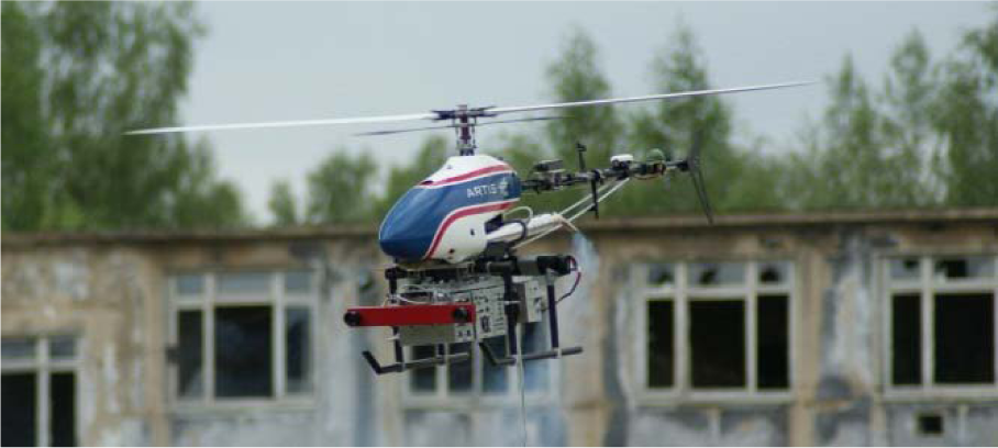
Mid-size helicopter, MTOW 14kg

Small-size helicopter, MTOW 1.5kg
The next chapters are organized as follows: After a brief overview of the related work, the general concept of the flight software will be discussed. Afterwards, an avionics concept is outlined for both helicopters. In the third chapter the software implementation based on the presented hardware design is briefly outlined. The implementation is tested and evaluated in the final chapter using a hardware-in-the-loop simulation which includes the avionic systems in the loop.
2. Related Work
Flight software for UA has been the focus of research for the past fifteen years. In many publications it has been shown that it has similarities to both robotic and space applications. A well-structured overview of related aspects of robotic and space software is given in [3]. The following section shall thus be confined to aspects of architectural representation which affect the scaling problem of this paper.
Many papers present architectures as abstractions in layers. One of the basic architectures is a three layer abstraction [4] which became the basis of many proceeding architectures. The layer called reactive controller forms the basis which is overlaid by the plan execution which coordinates the mission in a reactive sense. The deliberative layer includes the third and less frequent task imposing most of the computational costs.
Research has been published which specifies these layers and adapts them according to several requirements. Incorporating decision making as an explicit layer results in a four layered architecture [5]. Within UA applications there is often the need for a parallel process, which deals with environmental awareness. Koo et al. presented a multilayer description consisting of a strategic planner, tactical planner and a controller supervised by a vision layer in [6]. A conceptual extension with respect to requirements of sensor data and which considers risk management is presented in [3] and its application in collision avoidance is proposed. Alternatively to segmentation into architectural layers, these modules can also be categorized into cognition layers (Perception, Cognition, and Action) from a situational awareness perspective [7].
Further focus has been placed on the communication between the modules as presented in [8], for example, where inter process communication is modelled as peer-to-peer pipes. Every process has one message queue. In general, the modules responsible for this data exchange are often included within the middleware. These aspects have previously been addressed using middleware like CORBA (Common Object Request Broker Architecture) in [9]. In [10], also based on CORBA, the authors focused on an avionics system divided into two parts – flight control and vision payload.
Due to its platform, independent Interface Definition Language, CORBA has advantages regarding communication within systems of a hybrid nature in relation to platform and programming language. This advantage comes at the cost of an increased implementation effort and a more complex system due to the translation workload in the multi-language environment. In [7], ROS (Robot Operating System) is chosen as middleware. However, ROS does not support clock synchronization and imposes its own architecture on all software modules. It is thus not suitable for introduction of scaling in existing systems.
In [11] and [12], a hub-like communication management is presented for the Berkely Plane UA. Here, communication includes a state broadcast between multiple UA. López et al. build a specific middleware for UA avionics [13]. In their approach, the middleware executes and manages the other modules. This approach has the drawback that the middleware becomes mandatory for each module. Based on that middleware, a service-oriented architecture is described in [14] and [15].
Aspects of the software architecture in the sense of intelligence abstraction shall not be discussed here, as there is extensive literature as shown above. The modules of the software presented in this paper can easily map to some of the previously mentioned architectures.
A focus of this paper is the scalability in light up to middle weight applications. To the knowledge of the authors, there is no complete architecture representation for the scalability and module interconnection from a perspective for integration in UA of different scales.
3. Software Concept
The overall aim of an UA, such as the one presented in the introduction, is automated flight. It flies through areas with obstacles that are not necessarily known exactly a priori and automatically accomplishes certain missions within that area. Additionally, the vehicle is equipped with mission-dependent payload.
The following gives a short overview of the smallest set of mandatory higher level modules that have to be integrated into the flight software. The four components for the flight software are sensor fusion, flight controller, trajectory generation and mission management.
The sensor fusion gathers sensor information and estimates the current state of the UA using estimation algorithms like Kaiman filters. A trajectory generator calculates the time-wise evolution of the position and attitude command of the UA, cf. [16]. The flight controller is an implementation of the control algorithms which can be arranged in a control cascade, consisting of rate, attitude, velocity and path control; cf. [17] or equivalent. Finally, the mission management is responsible for the coordination of mission elements. It receives the mission from the GCS and generates commands for the flight control system [18].
These components are dependent on the current equipment and mission of the vehicle. The sensor fusion incorporates all primary sensors, which might, in general, not be exchanged regularly. However, if applicable, a particular payload can be included as well. Vision can support navigation and be included in the sensor fusion, as presented in [7]. The controller might be dependent on a certain payload as well, for example, with swing loads.
Additionally, modules for logging and health monitoring are required. These modules ensure the supervision of the safety of the.
All these components are introduced in Figure 3. The figure shows the two aspects of what is often referred to as an “unmanned aircraft system”, the (ground) control station (GCS) and the UA itself. Both sides can be distributed on different computers or computational units. The GCS can be separated into UA operations and the operation of the payload.

Information flow of the flight software and ground control station
Especially for small scale UA, the on-board components are distributed on different computational units, as will be shown later. The figure hence categorizes modules as being lumped or distributed. The lumped modules run on one computational unit alone, while the distributed work on different units, optionally requiring an information exchange.
The communication flow shown in the figure illustrates the concept of inter-module communication. There is one uplink between the ground control station and the UA. The reason is that on-board hardware interfaces and weight resources are limited on small systems. However, for bigger systems additional uplinks may be equipped implying a dedicated management of suitable up- and downlink channel selection. In that case, payload control might directly communicate with payload components on-board. For scalable systems, these links are optional and therefore are not shown.
There are actually two different aspects of the communication used for inter-module data exchange. A subscription system analogous to a bulletin board and direct data links. The communication might be implemented using a suitable middleware as highlighted in the related work section. However, in this case, for three main reasons, the communication was implemented from scratch. This was done in order to fulfil the requirements for this particular application, gain knowledge and, most importantly, make the communication module as light as possible. As communication and time synchronization are the major aspects of the scalability they are described in more detail below.
Generally, distribution across different computational units can be carried out at any of the communication pipes. However, some criteria have to be considered. Not fulfilling these criteria also corresponds to the identified hazards of a functional hazard analysis (FHA) [26] that has to be performed for certification considerations (Section 0). The criteria consist of the following items:
Communication will cause additional delays to the data. Software modules may only be separated hardware wise if the connection ensures that the client module receives the required data in time. In the example shown below, the flight controller receives the state data of the UA delayed by an additional network channel. This requires the controller to have a sufficient time-delay margin. The amount of data to be transferred is smaller than the bandwidth of the hardware interconnection. The overhead introduced by the additional layers that the data runs through does not cause too extensive a computational burden.
On the other hand a separation has to be carried out:
if the subset of modules would otherwise exceed the capacity of one computational unit, if the amount of interfaces required for peripheral components exceeds the number of those available.
Furthermore, separation can enhance the security of the system because the core system can be separated from a rather experimental payload. More sophisticated but experimental algorithms might be separated from more robust ones as a fall back solution, as was done for the sensor fusion described in [19].
Logging shall not be discussed in more detail, as there are numerous ways of completing the task, which are strongly dependent on the platform in use. It has to be kept in mind that logging can, however, place significant loads on the system if the gathered data is extensive. If debugging of a particular algorithm requires costly logging, this might actually be one criterion for its development on a bigger system with sufficient computational power to handle the logging.
The remaining support modules needed for the presented architecture are outlined in the following sections.
3.1 Scalability Aspect: Health Monitoring
Health monitoring is one support module of the flight software. Figure 4 shows its concept. Callbacks can be registered which define health data, states and corresponding actions: A data callback is registered which the health monitoring uses to gather the required data at a specified frequency. A corresponding criterion is registered which is used to determine the state of the module based on the data just gathered. Finally, a number of pairs is registered which consist of the possible states and callback to their corresponding actions.
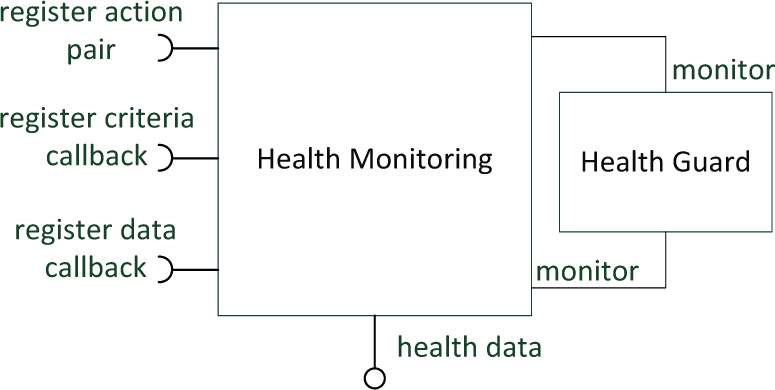
Health monitoring including its guard (UML semantic)
Using this approach, the monitoring remains independent of the hardware, each piece of equipment and desired module can register itself and will automatically be included within the monitoring.
The task of the health guard is to check the existence of the health monitoring and in case of a crash to restart it. It must therefore be informed of any registering process to be able to recreate the health monitoring in its complete state before a crash. Vice versa, the health monitoring checks the existence of the health guard. The health monitoring module offers a data structure for logging and transferring to the GCS.
3.2 Scalability Aspect: Communication
The communication connects all the different modules and processes on a UA. We decided to build a communication module that manages the communication between the UA and its ground control station, between applications on distributed hardware on-board and with other UA. The communication module is designed so that it can easily be integrated into existing modules and interfaces.
The communication module has to fulfil several requirements. First of all it should be as fast and involve as few computational overhead as possible, as avoiding delays is crucial for many algorithms. On the other hand it needs to be secure and reliable. As it also separates different modules from each other, it may also be regarded as a security layer in some cases.
A third requirement is that the communication structure is sufficiently flexible. It shall be possible that communication partners change over time. New processes may be started or obsolete ones closed. None of these dynamic changes in the communication structure shall effect any other existing communication connection. The communication itself can be divided into four different types:
Bulletin board data: Periodically updated data which might be used as an input to several modules: Usually sent in small to mid-size packages, less than one kilobyte in size. New values override old values. If one update does not reach the receiver, sending the next update without recovering the missed transfer will typically not cause a failure. This data is published on a virtual bulletin board and can be subscribed to by all interested applications in the network. Single-shot messages: Requests, commands or answers to requests, sent to a dedicated module: These are usually small packages, but are sent only once. Receiving these messages is crucial. Streamed data: Updates for larger data which might be used as an input to several modules: In order to save bandwidth only incremental updates are sent with each step. It is critical that all messages reach the receiver in the correct sequence to avoid inconsistent states. File transfers: Data that is too large to send in one package and need to be separated into several packages: Usually the receiving algorithms are not designed to interpret the data before they are completely and correctly received.
These four types are supported by the communication module. The implementation is based on so called topics. A topic is specified by an identifier as shown in Figure 5, which consists of three elements: One identifier for the receiver, one identifier for the sender and one for the transmitted data type and semantic.
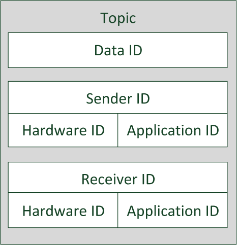
Topic Identifier
The identifiers for the sender and receiver are composed of an identifier for the hardware the application is running on and an identifier for the instance of the application unique on that hardware. The application identifier is generated dynamically at the start of the process and not predefined, e.g., during compile time. Thus, it is possible to execute multiple instances of the same application with unique identifiers on the same hardware.
So called slots are used to access the topics as sender or receiver. Each application can assign slots to existing topics. Typically, slots with the same topic identifier should always – after some delay of communication – hold the same data. Slots are divided into sending and receiving slots. For each topic there should usually be just one sending slot at the same time.
The sending slot determines if the connection needs to be secure. This is the case for single-shot messages, streamed data and file transfers. In that case the sending process is asynchronous and the calling function can be notified if any transmission error occurs. Furthermore, that slot can also distribute large data into several packages guaranteeing that the transmission will be done in sequence and completely.
Receiving slots will hold an actual data package until a new one is received. For the communication of streamed data and commands, receiving slots can also trigger events in order to notify connected algorithms of incoming new data. It is guaranteed that all notified algorithms may react to the event before the next data is received. For bulletin board data, the receiver identifier of one topic is set to “any interested entity” instead of a specific receiver. The data is then distributed to any receiving slot having the same topic ID. Behind the scenes this is ensured by subscription the alternative, a broadcast, would waste bandwidth.
A register of all known potential communication partners and their application names is held in each process. One process per hardware holds the so called “master” application register. The master register exchanges his knowledge of the actual network with all the other master registers on different processing units. It shares all news with the local registers.
Figure 6 shows an exemplary situation. The knowledge of the complete network is distributed, so the application register of Hardware Unit 1 and 2 will also be informed of the existence of the application at Unit 4 although there is no direct link. If the process holding the master register is closed or aborted – such as Application 1 of Unit 2 – any one of the other processes on the same hardware will automatically take its role. However, all communication will take place between reachable partners directly so that a failure in any other module or master register will not interrupt the communication.
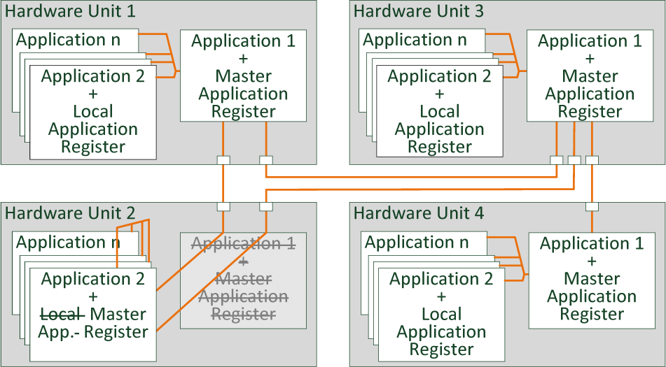
Communication Handling: Local and Master Application Register in different applications on distributed hardware of one network
The communication module also abstracts the technical implementation of the data links between the different hardware. It can send the data packages over (wireless) TAN as well as serial connection between two processing units.
The communication module also collects information about the communication taking place, such as the frequency and bandwidth between communication partners. That information can be used for routing as well as for the health monitoring module.
3.3 Scalability Aspect: Time Synchronization
The decisions and actions of an UA are usually based on the mission and the measurements of various sensors. To fuse the datasets of different sources correctly and to interpret them, it is essential to have consistent timestamps. Furthermore, concurrent information and commands can only be interpreted correctly if their timestamps can be correlated to the local on-board clock.
There are various ways to achieve consistent timestamps are mentioned in literature. If the delays in the data acquisition are known or negligible and processing is performed on the same computer, no further efforts are required. Thus, some UAS collect the sensor data on one processing unit connected to one clock before further processing [12]. For the presented scalable flight software, it is not necessarily known a priori how many computational units are used. Furthermore, we explicitly want to make time delay investigation possible where needed.
Some UAS use network servers and clients to synchronize the system clock of all the connected hardware either to each other or to GPS time [7]. However, this method can have some drawbacks. First, GPS might not be available as a reference all the time. Second, adjusting the clock might invalidate old data, time stamped before a time shift. Third, if the data exchanging partners are not all connected to each other constantly, as in cooperative UA scenarios, it might be impossible to synchronize all the UA correctly. For example, if two non-synchronized UA detect inconsistent phenomena at different times and report to a third, it might be impossible to determine the most recent.
If the time synchronization is done by a dedicated server, as for the precision time protocol (PTP) concept [20], a special handling should be used in cases where the server is not available, e.g., due to software or hardware failures.
Römer suggests estimating one function to convert the timestamps of different processing units for each pair of communication partners instead of adjusting the onboard clocks [21]. The estimation of the converting function is done in two steps.
First, the communication delay is estimated. This is achieved by sending the time difference between the local time of a package and the sending time in the remote package back to the sender. This is also done in the PTP, the network time protocol and various other time protocols [18, 20].
Second, timestamps of the remote system are collected, the communication delay is eliminated and the conversion function is estimated, for example, by linear regression. Some methods for the estimation are presented in [23]. The conversion functions are stored in each process and sorted by the related hardware unit of the communication partners, as shown in Figure 7. The first application on Hardware Unit 3 is to communicate with the application on Hardware Unit 1 and, therefore, to estimate the convert function for that hardware timestamps. The application on Hardware Unit 1 also communicates with an application on Unit 2 and, therefore, needs to estimate two convert functions, for Hardware Unit 2 and 3. Exchanged estimated functions between the communication partners can be used to determine initial values for the synchronisation and plausibility checks.

Time synchronized applications on different hardware
The package headers of the communication protocol already include a sending timestamp. Additionally, the estimation of communication delays is also important for the communication module, e.g., for route-selection. Thus, the time synchronization can easily be integrated into the communication module. Only an expansion of the package header with two 32 bit values for the last measured time difference between the sending time on the remote hardware and the last local receiving time is needed. If the communication traffic between two processing units is frequent enough, no further packages for time synchronization need to be sent.
4. Concept of the Avionics
The previous chapter showed the software concept. This section outlines the avionic systems for both helicopters. Afterwards, the implementation will outline the specific aspects for these avionics.
The avionics system of the 14 kg helicopter is based on an Ethernet interconnected PC104 system which is separated into one Linux-based payload computer (FC 2) and a QNX-based flight computer (FC 1), see Figure 8. Optional wireless LAN connections to the GCS are not shown.

Interconnection block diagram of the small-scale helicopter avionics based on Gumstix boards
The hardware concept of the miniaturized avionics is shown in Figure 8. In order for it to be compatible with the PC104 system, the hardware interconnection is established using a miniaturized 100Mbit Ethernet LAN switch. Three Gumstix form the computational units. Gumsitx are small processor boards equipped with ARM Cortex A8-based processors designed in an open source hardware concept.
Gumstix 1 handles the communication with the ground control station over a serial modem and is also connected to the safety electronics which on the one hand handles the actuator driving and on the other hand does the switching between automatic and manual mode for the safety pilot in case of failure. From an algorithmic perspective, Gumstix 1 handles all the loops of the flight control system and the mission management.
Gumstix 2 calculates the state estimation based on the sensors connected to this board. A Sonar is used to detect the height above ground during landing and take-off. It also uses a single or differential GPS. An integrated inertial measurement unit (IMU) and magnetometer (Mag) solution completes the basic sensor equipment. These first two processor boards are operated using QNX. The third Gumstix handles vision applications based on a Linux derivate. It can either be equipped with a small scale camera or a laser scanner with a weight of less than 350g.
This avionic system is mainly designed so as to be easily extendible with further LAN capable hardware modules as well as ease in exchange of different components. As stated in [24], flight software for space applications is tightly coupled due to limited recourses. This is true for small scale aircraft too. However, by designing the avionics as described here, flexibility in the sense of exchangeable modules is created. Whole payload modules can be added and exchanged, including the dedicated computing unit and not only the sensor itself. Only the compatibility of the software interfaces has to be ensured. As both avionic systems are based on the same concept, they are what we call hardware equivalent.
Note that this particular assignment of tasks to processing units is neither the optimal workload distribution nor optimal from the perspective of the algorithm requirements. Separating flight control system and sensor fusion, for example, will cause additional delays to the helicopter state data due to the helicopter state being transmitted over LAN. The number of hardware interfaces, however, demands a separation so that all the sensors can be equipped to one board and thus the servo driving board to another.
5. Implementation
In this chapter an implementation of the software concept is outlined that eases the exchange of the modules between different scales of avionics. The software runs in separate processes on the PC104 avionics system and is distributed to a set of processing units on the Gumstix variant. A further subdivision into even more processes is certainly possible. Nevertheless, this refactoring process is meant to be continuous. Separation into sub-processes will only occur if certain hardware requirements demand it in order to maintain a complexity as low as possible.
Figure 10 presents the structure of the software. The colouring is identical to Figure 3. Every process contains instances of health monitoring and logging. The interfaces symbolize the exchanged data transmitted either over LAN or in shared memory between processes. The flight control and mission management process is also responsible for ground control communication. In this role, it also coordinates the remaining processes using the control and observer modules.

Interconnection block diagram of the mid-scale helicopter based on two PC104 systems
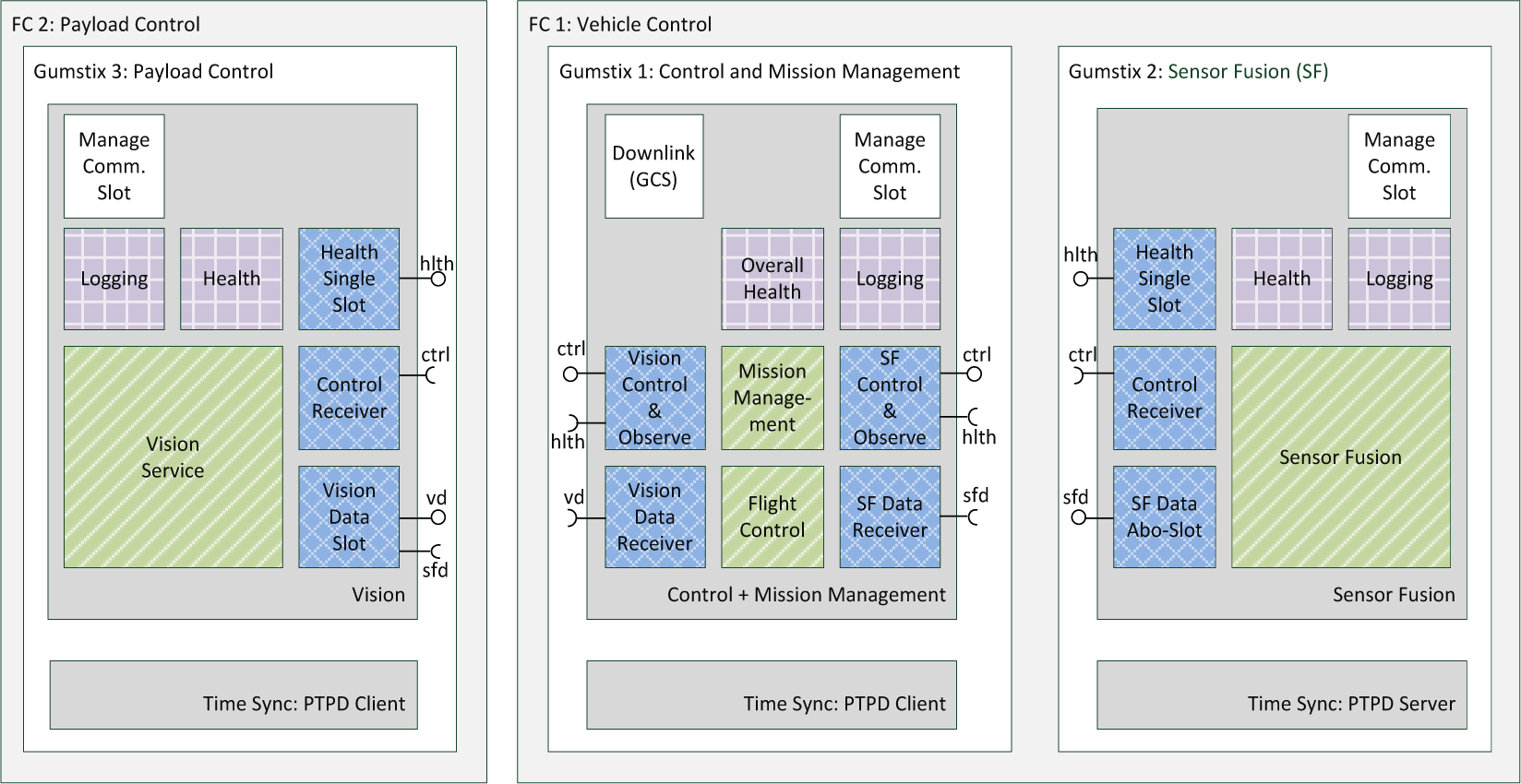
Implementation of the flight software for scaling between three processing units in the case of the Gumstix avionics and two for the PC104 variant
The control and observer modules make sure that every command received from the ground station is correctly transferred to the remaining processes (ctrl) and checks for the correct reaction on the other process side. Health data (hlth) is transferred to the management process as well as sensor fusion data (sfd) and vision or payload data (vd).
The time synchronization of the different processor units is implemented using a daemon-based implementation of the PTP according to IEEE 1588 [20]. This implementation does not enable time synchronization with the ground station via the uplink and other cooperating UA. This will be enabled as soon as time synchronization is fully included within the communication framework as previously presented in the time synchronization chapter. The achievable synchronization accuracy is below 1 ms according to the self-diagnostics of the synchronization processes. Health monitoring of the communication and estimation of the transfer delay is hence possible.
6. Proof of Concept
This chapter discusses results of a hardware-in-the-loop (HIL) simulation as an example of the tests performed. Figure 11 shows the general test setup of the HIL setup. The complete avionic computational units are integrated as they are in flight. The real time simulator measures the servo signals of the helicopter, calculates the corresponding flight mechanical responses and generates sensor emulated signals based on these computations. The protocols of the sensors are completely emulated and are connected via the same hardware interfaces as the real sensors would be.

Hardware-in-the-loop-simulation
From the computational units and the software perspective, there is thus no difference compared to real flight. To achieve identical flight behaviour, the flight mechanical model of the 14kg midiARTIS helicopter is used for both avionics. The flight mechanics consist of a linear hover model with eight degrees of freedom. Nonlinear extensions cover external forces. Furthermore, flight test-based error models of the sensors as well as identified actuator models are simulated.
This setup enables identical flights for the different avionic and software architectures and real comparison of the variants' performance is possible. The vehicle is operated using the ground control station, again identical to a real flight scenario.
For the sake of brevity, we limit ourselves to one example path shown in Figure 12. The reference implementation, denoted by PC104 single, is the original implementation. It contains guidance navigation and control algorithms identical with the scalable version. It differs from Figure 10 by removing communication classes in a single process implementation and missing time synchronization components. The PC104 distributed version consists of the scalable software architecture, where the sensor fusion and flight control processes run on the flight computer of the PC104 avionics. It is apparent that there is no significant difference in flight performance compared to the original implementation.

Example path flown with different avionics and software combinations
The final implementation is the multi-process version, compiled for the ARM Gumstix avionics presented in Figure 9. The flown path is nearly the same as the original. The slight difference from the reference implementation is caused by the additional delay due to the LAN interconnection between the sensor fusion and flight control system. The delay was measured to remain between 2 and 8 ms.
6.1 Certification Considerations
ARTIS is an experimental vehicle, therefore, the certification of its flight software using correspondent standards [25, 26] is not the main focus here. Nonetheless, a preliminary FHA [25] adds three main hazards to the system, compared to the previously existing monolithic system architecture. The hazards have been outlined in Chapter 3 as required criteria: (1) too large a communication delay is introduced, (2) communication data exceed available bandwidth, (3) too large a communication overhead is introduced. Additionally, the scalable architecture alters the overall system design, but the software level classification [26] of previously existing modules is not affected.
With these FHA results in mind, the communication module, as well as aspects of time synchronization, fall into the DO-178C software level A [26], where a failure might cause multiple fatalities with a loss of the aircraft. Since safety considerations are not the core of this papers' contribution, only a qualitative analysis will be provided for the proof of concept. Further reading on recent certification considerations of ARTIS can be found in [27].
Tests and analyses as well as HIL simulations showed the communication delay to remain below 8 ms. Therefore, the resulting flight path only differs marginally. Measurements showed that the bandwidth used also stays well below the hardware specification for the network traffic. The overhead for managing the network traffic has hence no impact on the flight performance.
The health module has no negative impact on the certification aspects of the architecture used, since it imposes no active action on other modules. However, future work will elaborate on the beneficial aspects of such a module.
7. Conclusion and Future Work
This paper presents a software concept for the flight of unmanned aircraft. A focus of this architecture is an application to vehicles of significantly different sizes. The software is thus focused on scalability and the optional distribution to different numbers of computers. Health monitoring, communication framework and time synchronization were outlined in depth.
It has been shown in a hardware-in-the-loop simulation that this software concept achieves equivalent flight performance compared to a monolithic implementation. It could thus be shown that the presented software concept is feasible for both scales of helicopter and will make the validation of future unmanned aircraft research significantly easier. Depending on the complexity and organizational demands of algorithms, the most convenient ones can be chosen. As soon as the algorithm has been integrated into the system, it will immediately work on the other variants as well, provided that the computational units can manage the algorithm's complexity and the algorithm handles the different UA flight properties.
Hardware concepts for two sizes of helicopter, a 14 kg and a 1.5 kg version, are presented. The avionic systems are based on x86 PC104 on the one hand and ARM Cortex A8 on the other. The scalability of the implementation of the presented software architecture is outlined in the example of both avionic systems.
It remains for future investigation to examine how an automatic priority setting of processes could relax computational demands on the small scale systems further. It is very possible that background and even distributed tasks can further increase the capacity of the small scale multiple computer system.
Footnotes
List of Abbreviations
8. Acknowledgment
The authors gratefully acknowledge the help of the team members of the unmanned aircraft department, especially Jörg Dittrich, Sven Lorenz and Florian Adolf, who provided support and helpful discussions.