
Abstract
This article gives an overview of the Mechanism Model paradigm. The mechanism model paradigm provides a framework to modeling mechanisms for robotic control. The emphasis is on the unification of mathematical models of kinematics/dynamics, geometric information and control system parameters for a variety of robotic systems (including serial manipulators, wheeled and legged locomotors), with algorithms that are needed for typical robot control applications.
Keywords
Introduction
The work presented in this paper describes 1) a unified approach for modeling the geometric and dynamic properties of a variety of robotic systems and 2) generic algorithms that operate on the model to perform common analyses needed in the control of such systems. The goal of this work is to provide a common representation for describing mechanical systems, such as robotic arms and wheeled and legged vehicles, and to provide built-in algorithms, such as forward and inverse kinematics and collision detection, that are needed in typical robot control applications.
The implementation of this approach will provide the Coupled Layer Architecture for Robotic Autonomy (CLARAty) (Volpe, 2001), (Nesnas, 2003), (CLARAty, 2005) on-board software with a more generic infrastructure for mechanism modeling and analysis. The modeling software covers mobility mechanisms, robotic arms, rover masts, and mechanical legs. The modeling software will provide the necessary information for realtime computation of kinematics, dynamics, and collision prediction.
Motivation
Current implementations of kinematic and geometric descriptions of mechanisms have different representation paradigms, which makes sharing kinematic and dynamic information very difficult. Furthermore, it is desirable for some applications to treat the mechanism as a whole body (for instance when dealing with rover-arm coordination algorithms). Some other applications may require the treatment of appendages as separate elements. For instance, one may wish to track targets from pointable mast cameras independent of the navigation of a rover.
Our modeling paradigm supports both views of mechanism control and provides for simplicity of information sharing. It incorporates flexibility without sacrificing ease of use or model fidelity. The unified modeling approach proposed has the following advantages. It:
Allows re-use of kinematic/dynamic and geometric information for a variety of robotic systems. Provides centralized storage for managing model information and configuration. Ensures consistency of the model information for use by multiple algorithms. Reduces duplication in model representation between rover mobility and manipulation software. Enables the development of generic algorithms for forward, inverse, and differential kinematics. Supports overriding generic algorithms whenever appropriate for optimal performance. Enables the verification of specialized kinematics algorithms against their generic counterparts.
This article contains software requirements for developing a unified mechanical model. It also contains requirements for algorithms and describes the interaction of the models with the rest of the on-board robotic software. In this paper, the term “mechanism” refers to any mechanical system and does not imply a closed loop mechanical chain.
Related Work
Attempts at creating a unified representation for mechanism are limited. The approaches found in the literature describe robotic systems from a number of system attributes, such as kinematic or geometric.
The most notable approaches are the DARTS/Dshell (Jain, 1991), (Rodriguez, 1991), the Open Robot Control Software Kinematics Package (OROCOS, 2005), the Operational Software Components for Advanced Robotics (OSCAR, 2005), (Kapoor, 1998), RoboML (RoboML, 2005), (Makatchev, 2000), ORCA (ORCA, 2005), (Brooks, 2005) and the Nucleus robotic control toolkit (Nucleus, 2005).
DARTS/Dshell is a high-fidelity dynamics simulator that models the motion of flexible multi-body systems under internal and external interactions. It has been used to model robotic systems and spacecraft. Applications include hardware-in-the-loop testing and off-line simulations. In the sequel, we will show how DARTS/Dshell's model representation is used in the mechanism model context.
The original goal of the OROCOS effort was to develop open-source software for robotics applications. The Kinematics Package in OROCOS is at the design concept stage and no software has been developed. It is intended to address more general mechanical systems and not be restricted to tree-topology systems. While the objectives of the Kinematics Package have been documented, the proposed approach for its implementation has yet to be clearly defined.
OSCAR provides utilities in the form of libraries for performing computations needed in analysis, real-time control, and simulation of manipulators. In addition to math utilities, it contains algorithms for performing generic forward and inverse kinematics, motion planning and dynamics. OSCAR offers many alternative options in its operations. For example, for motion planning, trajectories can be generated using trapezoidal, spline or motion blending algorithms. OSCAR currently appears to allow only the modeling of serial-chain manipulators. OSCAR's primary application is robotics education. While OSCAR provides generic software utilities for robot arms (serial-chain manipulators) the approach presented in this paper models more general kinematics systems.
Problem Statement
The CLARAty architecture is a reusable software framework for operating heterogeneous mobility and manipulation platforms. Model data in the existing CLARAty software system is dispersed and is sometimes duplicated in multiple software sub-systems. The heterogeneous nature of the mechanisms supported by CLARAty introduces the need to have a unified representation covering mechanical and geometric properties as well as algorithms for typical robot control applications.
To enable CLARAty developers/users to build manipulators and mobility models more efficiently and systematically, we need to unify geometric, kinematic, and quasi-static representations of mechanisms. We anticipate reduced development time and costs and improved software quality with the transition to a centralized model database.
Although the body of work presented in the literature covers different aspects of our problem (e.g., serial kinematic chains and real-time control), there is no approach that covers all the types of mobility mechanisms covered in CLARAty. Moreover, even though the work presented in the literature provides algorithms for robot control applications, they all seem to lack a very important property, that of geometric representation, to allow the integration of collision detection algorithms. This functionality is critical for the safe operation of autonomous robots.
Approach
To provide a unified representation of heterogeneous mechanisms, we developed a new approach to model robotic systems for real-time control and computation. The unified representation is based on the DARTS/Dshell approach with the following differences:
The Mechanism Model of CLARAty is designed for efficient, high-speed closed-loop control. It is also designed to serve multiple clients simultaneously. DARTS/Dshell uses more detailed models (body flexibility, actuator and transmission modeling, etc.) in a single thread for high-fidelity simulations of mechanical systems. Simulation software and control software solve complementary problems (e.g. simulation software solves the forward dynamics while controls software solves the inverse dynamics).
This article is organized as follows: Section 2 provides the general requirements that the software architecture must address. Section 3 presents the design of the mechanism model paradigm. Section 4 summarizes the types of constraints handled by the architecture. Section 5 explains the model data input. Section 6 summarizes the generic algorithms available in the architecture. Section 7 describes how the Mechanism Model paradigm fits in the CLARAty framework.
General Requirements
The Mechanism Model paradigm unifies the representation of kinematic, dynamic and geometric information, while separating the computational algorithms from the control algorithms thus making it independent of the hardware. To support different algorithms the Mechanism Model must be capable of the following computations:
Kinematics computations—forward, inverse, and differential kinematics. Quasi-static computations of forces and torques considering: joint flexibility (stiffness), gravity force and other applied forces, gravity deflection. Environmental contact constraints—position, force, torque, and stiffness. Resolution of multiple simultaneous kinematics constraints. Collision detection.
Mechanism Types
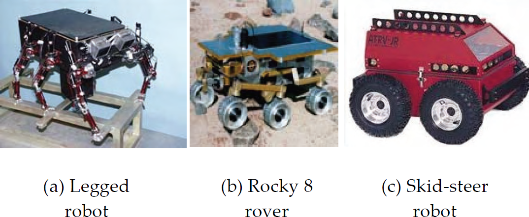
The types of mechanisms that can be described in the Mechanism Model paradigm include (Fig. 1):
Serial manipulators—multi-degree-of-freedom robotic arms, masts, and legs. Simple closed-chain mechanisms. Wheeled locomotors—multi-wheeled mechanisms with different drive and steering configurations. Legged locomotors—multiple legs attached to a body. Composite mechanisms—a combination of the above.
Composite mechanisms
Because of the underlying tree topology of the mechanism model, it will handle parallel structures by breaking the closed chain to be represented in the tree topology and solving for the closed chain using joint or position constraints.
A mechanism is represented as a tree topology with rigid bodies connected to one another via joints. The tree topology captures the geometric relationships between sensors/actuators and bodies. It serves as a repository of mechanical model information, which includes fixed (non-articulated) transformations, joint constants that do not depend on articulation values and component geometry. As a result, the proposed tree representation is stateless: position, velocity, and acceleration information relative to an inertial frame is not stored in the mechanism model. This is an important feature because it will enable various system states to be updated at different rates and enable the use of different parts of the tree at a time. It will also allow algorithms to use the mechanism model tree to predict future states for any given input state. The trade that is made here is the cost of re-computing derived states vs. making copies of mechanism model for each client application and keeping all their internal state up to date.
From the Mechanism Model perspective there is a single inertial frame, which acts as the root of the tree. This is important for creating composite mechanisms from identical components. For example, if we have a six-legged robot with identical legs, we only need a model for one of the legs and we can then create the robot by inserting the leg model at the mounting point for each leg.
Geometric information (for example for use in collision detection) is kept in the same model tree. The geometric model is hierarchically defined in terms of the bounding shape information of the physical components (Fig. 2).

A mechanical component an its bounding shape tree. Leaves of tree defines finest shape
The geometric description of a body is defined in a manner consistent with the bounding shape proposed by Leger (Leger, 2002).
In the Mechanism Model, a body contains a bounding shape tree (Fig. 2) that describes containment relationships among the geometric objects of a single body. As an extension to (Leger, 2002), the bounding shape tree describes different levels of granularity for the geometry of the object with the finest bounding shape resolution at the leaves of the tree.
Bounding shapes are represented either as 2D or 3D shapes (e.g. we represent terrain surfaces and walls by 2D open meshes and manipulator links by 3D shapes such as cylinders, boxes, spheres, and/or convex hulls).
There are two types of constraints handled by the Mechanism Model: Joint and Cartesian constraints. Joint constraints are constraints that couple a joint to another through a linear or nonlinear relationship (e.g., qi = f(qk), where q is a generalized joint coordinate). An example of a joint constraint in a physical system is the rocker angles in the Mars rovers. The rocker angle on the left side of the rover is always the negative of the rocker angle on the right side. Joint constraints can also be used to model a screw motion where the linear travel has a fixed relationship to the rotation angle. Cartesian constraints are further divided into: end effector and contact constraint. Contact constraints are used to specify the desired surface contact between two frames, while end effector constraints are used to specify the desired absolute or relative position of a frame.
Model Data Input
Mechanism model parameters are specified in an eXtensible Markup Language (XML) (The World Wide Web Consortium, 2005) input file (Nesnas, 2005). Each mechanism or appendage is defined in a separate XML file and a complete mechanism model is assembled by reading in multiple XML files (e.g. for a Mars rover, arm, mast, and mobility models are stored in separate files). The mechanism model file defines necessary mount points by name to attach appendages defined in separate model files.
The input parameter file supports a set of required kinematic parameters for the selected kinematic representation and a set of optional dynamic parameters such as the center of mass, inertia matrix, and bounding shape tree. Kinematic information can be represented using either homogenous transforms, zero position (also known as product of exponentials) (Murray, 1994), Denavit-Hartenberg where the reference frame of the i-th body is located at the i+1-th joint (Paul, 1983), (Spong, 1989), or Denavit-Hartenberg with Craig's modification where the reference frame for the i-th body is located at the i-th joint (Craig, 1989).
Regardless of the representation, model parameters are converted to an internal tree representation with z-axis aligned with joint axes. We treat each body as having a single joint that ties the body to its parent in the mechanism model tree. This approach is general enough to enable modeling of mechanisms of various types and simplifies the software structure (Fig. 3).
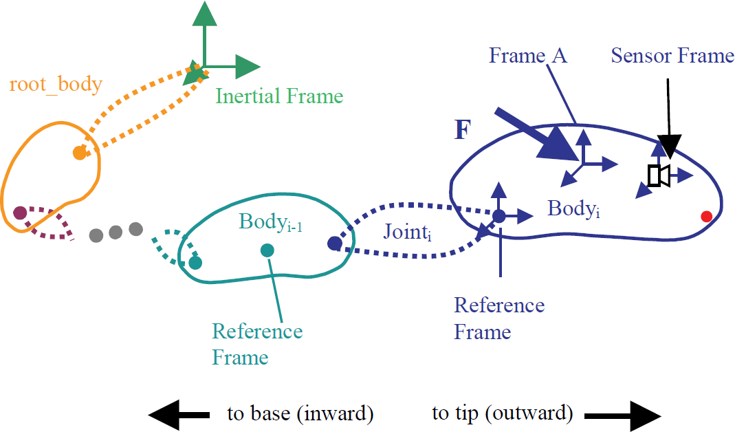
Mechanism model: bodies and joints
The choice of coordinate frames is consistent with the following conventions
For single degree-of-freedom joints, the z-axis is aligned with the articulation axis. For multiple degrees-of-freedom joints, the z-axis is aligned with at least one joint axis. The body reference frame is located at the center of rotation of the revolute joints.
Typical robot control algorithms include generic forward and inverse kinematics and collision detection. Facilities will be provided to allow users to by-pass the generic built-in algorithms with more-efficient customized specific implementations.
Forward Kinematics Algorithm
We have implemented a generic forward kinematics algorithm to determine relative pose of any frame in the tree with respect to another. The algorithm uses joint angles to compute relative poses between successive frames in the tree using depth first tree-traversal.
Inverse Kinematics Algorithm
A built-in generic inverse kinematics algorithm will be implemented using a constrained optimization (Fletcher, 1970), (Powell, 1983) numerical approach. Constraint management software is used to administer the generic solution for inverse kinematics problems based on the type of Cartesian constraints. The solution of a general set of Cartesian constraints that simultaneously apply to the kinematic system, is found through an iterative numerical approach. The constraint manager sets up the Cartesian constraint vectors to solve for an equivalent composite Jacobian matrix, and then uses a constraint solver to determine the configuration of the kinematic system that best solves for the set of Cartesian constraints. This approach will handle multiple simultaneous constraints and determine the solution that best (in a least-squares sense) satisfies the constraints while maintaining the kinematic structure of the mechanism. This approach can be easily extended to incorporate additional optimization criteria.
Collision Detection Algorithm
We define the geometry of each physical object as a hierarchy of composite bounding shapes, which is adapted from Leger's approach (Leger, 2002). At high levels in the hierarchy, one or more geometric objects are used to bound the physical object. At lower levels in the hierarchy, a more refined geometric model is possible by using many smaller objects (Fig. 2). The efficiency of this algorithm is obtained by checking for collisions between objects at high levels of the hierarchy and penetrating to deeper levels only when a collision occurs between high-level objects.
Although currently there is one collision detection algorithm, the framework is general enough to support others that use bounding shapes.
Interfacing Mechanism Model with CLARAty Control Abstractions
CLARAty provides a number of control abstractions including locomotion and manipulation abstractions. The mechanical model for the components defined by these abstractions is expressed in terms of the mechanism model. In this context, the mechanism model can be used either as a stand-alone abstraction for kinematic analysis, or as part of the control software for the robotic system.
When the mechanism model is used to describe abstractions such as manipulators or locomotors, interface abstractions are defined. These interface abstractions and their corresponding control abstractions enable the mechanical sub-system to be controlled independently. For example, a system with a rover and a manipulator arm can be treated as two independent control systems by utilizing the Manipulator|Model and Wheeled|Locomotor|Model interfaces for the arm and the rover respectively (Fig. 4). Alternatively, one can use the Mechanism_Model abstraction to simultaneously coordinate the arm with the rover motions. In this approach, one can think of the Mechanism Model as a database that is filtered through a Manipulator_Model object and a Wheeled_Locomotor_Model object or a complete Mechanism_Model object. The filter presents a facade to the user of the respective object with built-in capability for kinematic or dynamic computations. Then the interface between the control and higher-level software (R8_Arm for example from Fig. 4) to the Mechanism_Model software (R8_Arm_Model from Fig. 4) becomes straight forward.

Example of using Mechanism|Model with CLARAty Manipulator control classes.
The process in using the Mechanism Model software is to first instantiate the model by initializing it with the model file then set the state of the model and call the respective algorithms.
Because of the generality of the algorithms in Mechanism|Model, they will be computational less efficient than customized algorithms that utilize knowledge of the kinematic structure of a specific mechanism. In some instances, the performance difference is negligible, as in the case of forward kinematics of a serial chain. However, developers can provide their own customized algorithms to replace the built-in generic ones when performance differences are significant, as in the case of the inverse kinematics of serial chains. For example, the R8|Arm|Model object in Fig. 4 can over-ride the inherited generic algorithms with its own custom algorithms. This flexibility allows users to combine the advantages of using the centralized database with the superior computational performance of customized algorithms.
The consistent and unified representation of mechanism model information for large robotics systems will not only simplify the software development of various robotic algorithms, but it will also reduce the risk of model mismatch and inconsistent representation in the software that can lead to catastrophic failures in flight systems. Several control and planning algorithms can leverage the kinematic and dynamic computations in flexible ways to enable efficient control of robots.
Much of the software infrastructure for model description and representation has been developed. We developed models for the rocker-bogie mechanism of the Martian rovers. The development of the generic forward kinematics is complete and work is underway for developing the constraint optimization and inverse kinematics.
The next step is to migrate existing CLARAty code base to leverage the new mechanism model for use by several algorithms such as navigation, planning, and control. The models will include all rover appendages, mobility mechanisms and new legged robots.
Footnotes
9. Acknowledgements
The work described in this paper was carried out at the Jet Propulsion Laboratory, California Institute of Technology, under a contract to the National Aeronautics and Space Administration. The authors would like to thank the Mars Technology Program for their support of this work. The authors would also like to acknowledge and thank Anne Wright, Raymond Cipra, Max Bajrachara and Daniel Clouse for their contributions.