
Abstract
This paper presents a novel developmental learning approach for hand-eye coordination in an autonomous robotic system. Robotic hand-eye coordination plays an important role in dealing with real-time environments. Under the approach, infant developmental patterns are introduced to build our robot's learning system. The method works by first constructing a brain-like computational structure to control the robot, and then by using infant behavioural patterns to build a hand-eye coordination learning algorithm. This work is supported by an experimental evaluation, which shows that the control system is implemented simply, and that the learning approach provides fast and incremental learning of behavioural competence.
Keywords
1. Introduction
Autonomous Robots supported by traditional artificial intelligent algorithms have been able to execute complicated tasks. However, for robots to be truly autonomous they must be capable of continuously developing within their environments. To achieve this continuous development, robots must create their own internal representations [1]. The way this problem has been solved in cognitive biological systems is through processes of structured growth, known as “development”. In artificial intelligence, this idea was introduced into robotics. Developmental robotics draws inspiration from various aspects of developmental psychology and neuroscience, e.g., sensory-motor coordination, emergent behaviour and social interaction [2]. We are interested in the very early development and growth of sensory-motor control and skills (e.g., robotic hand-eye coordination), because early experiences and structures are likely to underpin all subsequent growth in crucial ways, thus agreeing with the suggestion that sensory-motor coordination is likely to be a significant general principle of cognition [3].
Robotic hand-eye coordination, which is a sub-category of robotic sensory-motor coordination, is one of the most important skills for intelligent robots to survive and work in unconstrained environments. Moreover, robotic hand- eye coordination is extensively used in a wide range of applications, such as vehicle manufacturing, space exploration, food packaging, and even oncological surgery, etc. [4]. A number of studies on robotic reaching and hand-eye coordination have been performed recently. In their research, [5–7, 25] attempted to have their robot autonomously build a distinct “eye-to-hand” formula for reaching. These approaches dealt with the robot's kinematic redundancy. In the work of [8, 9], a new type of constructive neural network was created to build a mapping system, in which visual perception was transformed into hand motor values. In studies [10, 11], a developmental learning algorithm was applied to obtain this type of transformation. Other developmental robotic hand-eye coordination systems [7, 12–14, 19–21] have used different neural networks to simulate some of the brain loops that control hand-eye coordination. Such research indicates that introducing brain-like structures into developmental robotics is regarded as an effective solution to robotic cognition [2]. The existing works lack infant behavioural features. However, we believe that several infant behavioural patterns have a significant effect during human development [15]. In this case, we propose to apply an infant behavioural feature into our robotic learning phase. In addition, we apply a simple sensory-motor map implementation to increase the robotic learning speed.
To solve the above problem, we apply a combination of a brain-like computational structure and a significant infant behavioural pattern to an autonomous robotic system to determine whether the robot's behaviour will mimic the characteristics of a human infant. By mimicking the mechanisms of the brain system, we learn important design principles for autonomous robotic systems and, thus, bring higher autonomy to developmental robotics. This research proposes a novel computational structure with a linking map mechanism to map visual stimuli to the robotic hand motor system. Additionally, to know how to control its hand, the robot uses a procedure similar to that of an infant's “repeat movement” pattern. In so doing, our robot obtains several features that are similar to those of human infants. Thus, our approach is useful for the implementation of high autonomy in autonomous robotics.
The remainder of this paper is structured as follows: Section 2 introduces the relevant background and a short review of related methods. Section 3 describes the proposed brain-like computational structure and the infant developmental pattern-inspired learning algorithm. Section 4 shows the experimental results and the implementation of the robotic system. Finally, Section 5 concludes the paper and points out import future work.
2. Background and Related Work
By implementing the core technique of the robotic reaching skills, a mapping from robotic visual sensory apparatus to robotic actuators is generated. Generally, human engineers calibrate traditional robotic hand-eye coordination systems. From the viewpoint of autonomous robotics, robots themselves are able to learn the mapping. If a robot obtains the ability to establish the mapping, the robot can achieve a high adaptive capability to work in changing environments, and even can learn to use tools.
Figure 1 shows a diagram of the hand-eye mapping problem. The system (diagrammed in Figure 1) obtains the location of a target in an image produced by a visual sensor; then, this information is converted to the eye-centred coordinate system. The eye-centred information is then transferred to the hand space via a hand-eye mapping system; then, the difference between the current hand position and the desired position is used to drive the hand motors. There are two frames of reference: eye-centred and hand-centred. The hand-eye mapping problem is thus formulated as finding the relationship between the eye motor space and the arm joint space, i.e., finding the mapping: f: (m1, m2) → (j)1, j2, …, jn), where m1 and m2 are the visuo-motor system's motor values, jp stands for p th arm joint motor value, and n is the number of arm joints.

A typical robotic hand-eye coordination diagram
Hand-eye mapping is highly non-linear, mainly because the geometries of body parts exhibit quite complex kinematics and visual distortion [16]. In this case, the non-linear approximation ability of artificial neural networks supports the implementation of hand-eye mapping [35]; e.g., in [7, 19, 21] self-organizing map networks are used for the mapping. Also, several recent works consider a simulated human brain structure to solve the problem of hand-eye mapping. For example, [12, 13] used radial basis function networks to simulate the V6A cortex in the human brain. [14, 22–24, 18, 34] applied neural networks to mimic the brain's distinct cortices. Furthermore, a new type of constructive neural network (a growing radial-based function network) was created to simulate the growth of brain development, in which the network's topological structure grew while, simultaneously, the network was being trained [8, 9]. Inspired by the above studies, we created a computational model wherein we reduced the complexity of robotic learning systems by simulating a part of the human brain.
On the other hand, scientists of developmental robotics focus on bringing developmental features into their research. In particular, theories from developmental psychology were proposed to build developmental learning algorithms for hand-eye coordination. For example, [10–11] implemented a developmental architecture for robotic reaching capability. [20] reported the use of random hand movements to find a correlation between their robot's vision and hand proprioception; thus, their robot can determine its body definition. However, in the training phase, the above researchers ignored imitating the developmental progress of human infants. We believe that processes that incorporate hand and arm (or other body parts) into a cognitive model are very important. Our belief is supported by psychological data; e.g., [26, 32] showed that infants do not make hand movements that are self-evidently target-directed until their fourth month of learning and developing. During the four months after birth, infants learn to control their hands via cognitive growth. This four month period is also seen as the rapid growth period for internal neurons in an infant brain.
We found that a behavioural pattern called “repeat movement” has an important impact on an infant's hand- eye coordination. When an infant masters gaze skills (i.e., the ability to saccade and fixate on a stimulus), he/she is able to locate and examine any moving object, even if it be his/her hand, arm or other body part. However, after tracking many movements of his/her own arm, he/she senses that the changes in eye proprioception are always in accord with the changes in hand proprioception. Sometimes, the infant may move, in a back-and-forth action, his/her hand to a new position and then back to the initial position to ensure that the changes in eye proprioception are caused by his/her hand. Thus, he/she realizes that the moving object is his/her hand, and it is under self-control. This behaviour in infants is known as “hand regard”. When this correlation between eye and hand proprioception is well established, hand regard behaviour declines, and infants then ignore their own hands and arms.
Therefore, our study proposes a computational structure to simulate the human brain cortex functions that are used in hand-eye coordination. A developmental learning algorithm completes the training procedure. This paper is a continuation of several of our previous publications. We assume, in this paper, that our robot possesses saccadic ability, as reported in our previous work [31]. The robot's hand performs sensory motor movements through sensory-motor exploration [29, 35]. In [30], we designed a simple method for robotic hand-eye coordination, in which our robot's eye merely followed its hand's end- effector. Neither infant's features nor brain-like structures are mentioned in the paper.
3. Brain-like Structure and Teaming Algorithm
3.1 Computational Implementation for Robotic Hand-eye coordination
Neuroscience findings of the four cortices of human hand-eye coordination can be summarized as follows: visual, lateral intraparietal (LIP), vasoactive intestinal polypeptide ventral intraparietal (VIP), and posterior parietal cortex (PPC). Visual perceptions rely on the visual cortex in the human brain. Lateral intraparietal (LIP) combines the following three kinds of signals: the position of the stimulus on the retina, the positions of the eye in the orbit, and the angles of the head. The LIP connects to the VIP area neurons which are supposed to code for the head-centred representation and also to connect visual and tactile sensations. The posterior parietal cortex (PPC) is recognized to handle reaching and grasping movements [27]. Based on these neuroscience findings, the computational model is designed to have two distinct sensory-motor mapping systems, similar to the various cortices in the human brain. However, the computational model contains two coordinate systems. Psychological findings [28] suggest that the head-centred coordinates be used as a common reference frame to guide reaching movement.
Influenced by the brain structure, the robotic learning model (in Figure 2) consists of four sub-models that support similar functions of the visual cortex, the LIP, the VIP and the PPC. The visual sensor (VS), which simulates the functions of the visual cortex, detects the objects and the robotic hand. The visual map (VM) provides saccadic eye movement functions. The periphery view sensor (PVS) combines the coordinates of the visual peripheral view and the camera's position into the reference frame's coordinate. The visual memory map (VMM) is used to implement the internal reference frame. The hand sensory-motor map (HSM) supports hand movements. The HSM's functions are similar to the PPC's. Additionally, a “link” structure is used to simulate the role of the brain's circuits that connect the VMM to the HSM. These maps and the link mechanism are described in the following sub-sections.

The brain-like computational mapping model
3.1.1 Basic Sensory-motor Map Structure
The visuo-motor system and the hand sensory-motor system are implemented by respective sensory-motor coordination models, whose prototypes have been used in our previous work [31, 35]. The sensor-motor coordination models are based on a basic sensory motor map structure. The map contains two channels: the first channel receives perceptive information, such as hand joint angles and the visual stimuli's positions within the images; the second channel is responsible for sending motor values to motor devices. In this paper, both the input and output values are two-dimensional.
The basic map consists of two-dimensional arrays of elements with each element represented by a receptive patch area known as a

The basic sensory-motor mapping structure
Because different maps' input values are distinct, we need to reduce the scale to [0…19] by using the following equations; otherwise, a stimulus cannot be located in its related map.

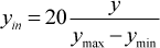
Where:
When a stimulus S(xin, yin) is put into a sensory-motor map, we calculate the distance between the stimulus and each field by:

Where:
Thus, the motor value is not obtained from a single field but from

Where:
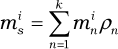
Where: min is the
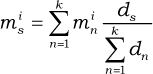
Thus, the motor values of the overlapped fields of a stimulus can be calculated by equation (6). Additionally, we can also use equation (3) to find a field
The basic sensory-motor map is created as a framework for saving our robot's learning results. This map can support the hand sensory-motor system, the visuo-motor system and the hand-eye system. However, each system's coordination varies, and the decoding methods are also different; thus, the following subsections describe how the basic map is used in each system.
3.1.2 Hand Sensory-motor Map
The hand sensory-motor map (HSM) maps the proprioception of the arm/hand workspace onto hand motor actions. Therefore, our robot exhibits hand sensory-motor movements. The hand sensory-motor movement can be described as follows: If a stimulus is created in the hand's proprioceptive space, the robot will drive its hand so as to move to the stimulus' position. The map's input is the hand's proprioception that provides feedback on the sensed position of a limb in space. This paper uses the hand's joint angle values to decode the hand's proprioception (
3.1.3 Visual Map
The visual map supports saccadic eye movement functions. The input to this map is the position in an eye-captured image of a salient stimulus, and the output is the eye's position in its orbit. The position value is used by the eye motors to drive the ocular muscles to rotate the eye, so that the eye moves to fixate on the salient location (see [31] for more details). Unlike the basic sensory-motor map's structure, the visual map also contains 400 (20×20) fields within a polar coordinate system. The polar coordinates simulate a human retina's structure. The fields in the boundary area are larger than those near the centre. Consequently, the fields in the boundary area make inaccurate saccadic movements, but the fields around the centre area create accurate saccades. Thus, the field number in the boundary area is less than the field number around the central area. The robot spends less time in learning the boundary fields. The setup, therefore, reduces the learning time for the saccadic function.
This VM's input is the visual stimulus's position (
Two parameters α and γ are used to define each field position; α is the field's angle from the coordinates starting axis and γ is the field's distance from the visual central point. The ranges of α and γ are set as follows: α ε [0,360°) and γ ε (30,462]. Each VM field's central position (α, γ) is calculated by αi =

Where:

Where, in our experimental setup, Δα is 18 and σ is the overlap parameter that is set at 1.2. Merging (7) and (8), we obtain:

Figure 4 demonstrates a visual sensory map, which is generated in [31]: the left figure presents the sensory layer, and the right figure is the motor layer. In the entire Figure 4, there are 94 fields generated in total, which indicates that 94 fields supply enough visuo-motor information to make saccadic movements.

The VM map at 94 fields
3.1.4 Visual Memory Map
As suggested in [28], the proprioceptive feedback arising from eye and neck positions is used as a reference frame to perform interactive actions with objects in extra-personal space. Therefore, a combination of eye and neck proprioceptive positions is used to define an object's position in space. However, our robotic system does not have a neck mechanism; therefore, only the eye's ocular muscle is involved in internal proprioception sensing. Since ocular systems have two DOFs, two variables
Equations (1) and (2) reduce the scale of
The VMM is similar to the mapping structure shown in Figure 3. The VMM also consists of a two-dimensional field array. However, the VMM's input is the ocular muscle's proprioceptive position
It is also important to note the different capacities in the VMM and the HSM. In the mapping model's architecture, each map contains a capacity parameter that indicates the field capacity in each map. A map with a higher capacity is more accurate, since a map consisting of more fields can accommodate more sensor signals and motor values. Accordingly, we set the VMM to have a higher capacity than the HSM. Therefore, the VMM contains 400 fields (20 × 20), which we define as the VMM's capacity; however, the HSM contains only 100 fields (10 × 10).
Such a sensory motor map implementation has three benefits: firstly, it makes it convenient to observe the internal changes during the training phase. Secondly, the map's structure avoids weight training, which is widely used in artificial neural networks; thus, the sensory motor map reduces the system's learning time. And thirdly, the map supports an online learning algorithm, which might be similar to a human infant's learning style. Additionally, the two-dimensional map can be extended to three dimensions. The three-dimensional data is perpendicular to that within the two-dimensional map. In this case, each field is not a circle but rather a sphere. The three-dimensional map is like a cube containing an array of spheres. The equations, which are used to access the maps, can be changed slightly to fit the three-dimensional maps.
3.1.5 Visual Sensor and Periphery View Sensor
The robotic vision system consists of two sensors: a periphery sensor and a central (or foveal) sensor. The periphery sensor detects: (1) new objects or object changes in the visual periphery area, and (2) the positions of any such changes (encoded by polar coordinates). The central sensor detects whether any objects are in the central (foveal) region of the visual field.
How can one map a salient object within the eye's periphery view to the VMM? The salient retinotopic position
By using equation (10), the PVS finds the corresponding position of the stimulus in the VMM. However, according to equations (9), the radius of a VM field in the boundary area is large; the PVS will produce a corresponding area, rather than a single point position. Therefore, we use the VM field's radius value to increase the point position to the scope of the corresponding area. As such, we obtain:

Where:
In this case, equation (12) defines a square area with the VMM. Any VMM field whose central position
3.1.6 Map Linking Mechanism
To achieve reaching behaviour towards stimulating objects, it is necessary to ensure that a stimulus captured by the vision system is delivered to the hand sensory motor layer. In this case, a transfer mechanism is used to deliver stimuli from the VMM to the HSM. Note that the links only exist between the VMM and the HSM. Each field has a variable
We allow each VMM field to have more than one link. However, because of the different densities in the hand and visual memory map, we do not set a fixed link number. Instead, we use the learning algorithm itself to explore the number of links in each field. The connection only occurs between the VMM and the HSM. Note that, in terms of the multiple-link setup, more than one HSM field can be invoked by one stimulus. In this case, we merge the motor values of these invoked fields by:

Where:
On the other hand, a salient stimulus may relate to a stack of VMM fields
To build the links, a learning algorithm is implemented as described in the next section.
3.2 Learning Procedure with a Repeat Movement Pattern
Several infant research results indicate that human infants obtain the abilities of saccade and hand sensory-motor coordination before they develop their hand-eye coordination [32, 33]. In terms of this viewpoint, we assume that our robotic saccade and hand sensory-motor coordination are also developed prior to its hand-eye coordination development. Therefore, this paper merely focuses on the learning algorithm of hand-eye coordination.
The flowchart of the entire learning algorithm is illustrated in Figure 5. The VS captures images and detects the position of a stimulus (

The flowchart of the learning algorithm
3.2.1 The Repeat Movement Pattern
A repeating movement procedure is plotted in Figure 6 (the upper three squares show the hand position above the workspace; the middle three show the corresponding fields of the hand positions in the VMM; and the lower three indicate the hand proprioceptive field in the HSM). The repeating movement procedure contains three steps, as follows:

The three steps of the repeat movement pattern
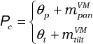
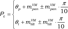
Step 1: Define the current hand position in the workspace as “P1”; then, use the VM to generate saccade movements to fixate on the stimulus. The current eye position (θp, θt) is sent to the VMM to find the corresponding VMM field
Step 2: Give the hand motors a random value to drive the hand and move to a new position P2. After the hand movement, the fixated object will disappear within the eye's vision centre, with the eye following the hand to P2.
Step 3: Move the hand back to P1. Use the VM to generate saccade movements to fixate on the stimulus. The current eye position is sent to the VMM to find the corresponding VMM field
To implement the repeat movement algorithm, short-term memory must be developed. Short-term memory, which can be updated during the running of the algorithm, stores the previous proprioceptive positions in the VSM and the HSM temporarily.
3.3 The Reaching Procedure
When its learning is complete, the robot achieves reaching capability. The reaching procedure's first few steps are identical to the learning algorithm (see the grey area in Figure 7). The VS detects the position of a stimulus (

Flowchart of the reaching procedure
4. Experimental Results
The experimental system consists of various hardware and computational components. The computational items include the learning algorithm software and hardware driver programs.
4.1 Experimental Platform
Figure 8 shows our hand-eye hardware system as a test-bed. This laboratory robot consists of two industrial quality manipulator arms and a motorized camera system. These are configured in a manner similar to the spatial arrangement of an infant's arms and head. The arms are mounted, spaced apart, on a vertical backplane and operate in the horizontal plane, working a few centimetres above a work surface. A computer-controlled pan and tilt colour camera is mounted above and looks down on the work area (see the top picture of Figure 8).

The experimental platform
4.1.1 Visuo-motor System
The camera system (see the bottom-right picture of Figure 8) is arranged to fixate on an object and perform saccades, like an eye. The visuo-motor system consists of a motor and a sensor subsystem.
The pan/tilt device provides two DOFs. The pan/tilt device effectively executes saccade-type actions based on motor values supplied from the generated VM. Each motor is independent and has a value (Mp for pan and Mt for tilt) which represents the relative distance moved in each DOF. The pan/tilt system also senses the motor's current location status, and uses two integer parameters to express location.
The bottom-left picture of Figure 8 shows a vertical view of the workspace: a white table, with green objects. Another green blob is mounted on the arm's end-point to represent a fingertip. The rest of the arm is ignored by the image processing software. In this arrangement, only the fingertip's movement can be detected by the vision system. This setup is so arranged to simplify the image processing task, especially that of object detection.
Note that the camera's vision covers the entire workspace. Therefore, a moveable eye system can observe everything in the workspace without changing its posture. However, if our robot applies a short-range camera, whose vision merely covers part of the workspace, the camera has to move to different angles to see all the objects. In this case, the approach can still handle the new camera.
4.1.2 Hand System
The laboratory robot arm uses only a two-DOF system in order to move horizontally in the plane above the workspace. Each rotational joint of the robot's arms has a motor drive as well as an encoder that senses the joint angle, thus providing a proprioceptive sensor reading. Each of the arms carries a very simple tactile sensor in the form of a fingertip contact device at the limb end-point. This fingertip probe is composed of a small touch sensor. The sensor detects in three directions, such that as the arm sweeps across the work surface, any objects encountered will be detected.
4.2 Experimental Results
Experiments were carried out to create the relationship between the VMM and the HSM, and then achieve reaching behaviour. The experimental procedure was as follows: the robot hand moved randomly above the workspace; once the robot eye sensed a stimulus, the learning algorithm started to build the links between the VMM and the HSM.
The overall experimental observations can be divided into two categorical stages: 1) First, because the VMM is blank or extremely sparse, there is no experience available. The eye always follows the hand's movement, and then uses repeat movements to create new links; 2) In the second stage, because most of the fields of the VMM have generated links, the learning algorithm is able to detect and filter out the robot's hand each time. Thus, the eye merely ignores the hand. However, occasionally the hand moves to a position that it has not visited before, and so repeated movement is generated to generate a new link. To examine the behaviour more carefully, two internal counters are set to record two different movement types: repeated movement and ignored movement. The former indicates that a new link is being constructed using this repeated movement; the latter signals that a link between the current eye and the hand field has already been created.
Figure 9 illustrates the increasing trends of these two types of movement. Over the first 10 movements, because there are no links between the two maps, all the movements are of the repeated movement-type; non-repeated movement does not exist. Between the 25th and 75th hand movements, the ignored movements increase slowly, so that the repeated movement remains the main movement-type. This situation does not change until around the 75th movement, when repeated movements begin to decline and ignored movements start to increase at a rapid rate. Eventually, at the 110th movement, repeated movements virtually stop, and ignored movements become the main movement-type. Therefore, the two curves clearly express the two developmental stages during the overall training phase. Fast learning occurs at the beginning of development.

The two types of accumulated movements during development
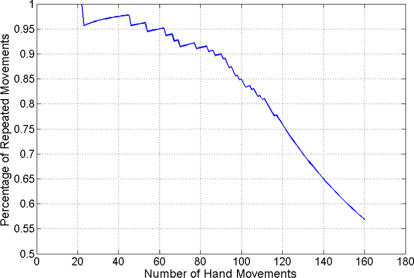
In order to clearly observe the changing trend of the entire developmental procedure, the percentage of repeated movements against the overall number of hand movements is shown in Figure 10. Before around the 80th movement, the percentages of repeated movements is always above 90%. The situation indicates that only a few ignored movements are generated during the initial part of development. Between the 90th and the 110th movements, the percentage starts to decease; however, the deceasing speed is slow within this range. After the 110th movement, the percentage value drops rapidly; in particular, the percentage curve becomes smooth at around the 120th movement. The smooth curve illustrates that the repeated movement never occurs during the end period of the robot's development.
The two types of movement during development
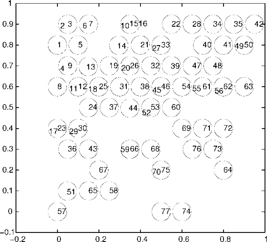
Figures 11 and 12 illustrate the final outcome of a set of experimental studies: Figure 11 presents the VMM and Figure 12 presents the HSM. In Figure 11, each plotted circle, identified by a number (1, 2, 3, etc.), exhibits a field-generated link that is matched to an identically numbered circle in the linked fields of the HSM (see Figure 12). As seen from Figures 11 and 12, the shapes of the two maps s are different because of the difference in the proprioceptive sensors. Moreover, in the hand map only, we see that several fields have more than one number, indicating that a field in the VMM would have more than one link. The shape of such fields (Figure 11) is quite similar to the hand proprioceptive shape encoded by Cartesian coordinates. This similarity perhaps implies that Cartesian coordinates are a better solution for hand-eye proprioceptive transformation.

The linked fields of the VMM
The linked fields of the HSM
Also, as seen in Figure 12, the bottom-right area contains fewer linked fields than the other areas. A few visual memory fields are sufficient to cover the remaining area. Therefore, the hand-eye learning does not need to build many links in this area. Based on this finding, it can be deduced that the learning algorithm can autonomously find where to develop more and where to develop less. This attribute of the learning system indicates that it can perform self-exploration and build its own internal representation.
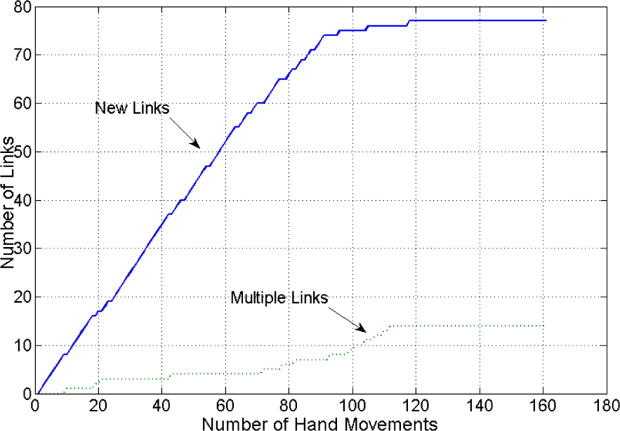
Figure 13 demonstrates the increasing trends of different types of links during the robot's development. We define a “new link” as the number of the original link and “multiple links” as the number of the links from linked VMM fields to the HSM. The number of new links increases rapidly at the beginning of the development, and only a few multiple links are generated during this phase. At about the 85th movement, the new links almost stop increasing, but the increase in the multiple links accelerates. However, this acceleration does not last long; it stops at about the 110th movement. Eventually, there are 14 multiple links and 77 new links in total.
The link curve during development
Depending on the hand-eye coordination learning algorithm, each visual memory field contains more than one link. Consequently, it is difficult to use Figures 11 and 12 to know which area contains more links. Therefore, Figures 14 and 15 are used to describe the link density in the VMM and the HSM. Blue indicates that each field contains a single link. The yellow and brown fields contain more links than the blue ones. Also, as seen in Figure 15, the bottom-right area has a low link density and the top-left area has high density. The yellow area indicates that the VMM's field radius is too large, such that one VMM field can cover many HSM fields. This high density area may drive the robot to use a high capacity VMM map (with smaller fields) to reduce the link density.

The density of the linked fields of the VMM
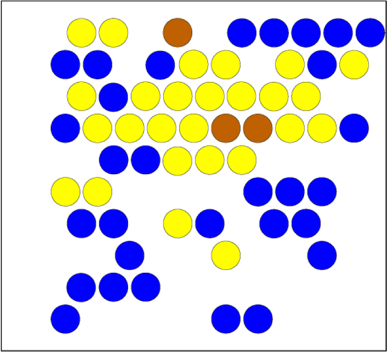
The density of the linked fields of the HSM
The experiments described above focus on the issue of the eye following a hand. To observe interactions between objects and a robot's hand, an object is put into the workspace in subsequent experiments. An object (painted green) is placed in 10 different positions on the workspace, one at a time. According to the learning algorithm (Figure 7), if the field related to the object's position in the VMM already has a link, a reaching movement will appear; otherwise, the robot's eye can merely fixate on the object, but the hand cannot reach it. Therefore, this interaction experiment was designed to run once every 20 movements, with the successful reach times recorded and plotted in Figure 16. Successful reaching rarely appears within the first 20 movements. However, after 80 movements, the success rate almost reaches 70%. This success rate shows that the present developmental learning algorithm is fast and effective. The fact that each of the green objects appears similar to the robot's hand, yet the robot can distinguish between them, is a significant feature of our system.
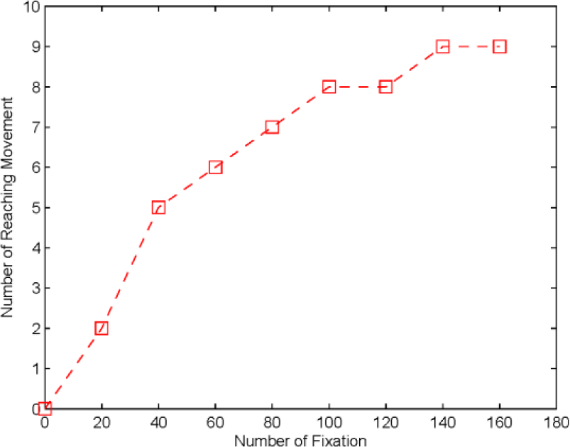
The reaching incidence rate
4.2.1 Discussion
The above experiments have demonstrated how our robot learns to map from its visual sensory system to its hand, and how the brain-like structure and the infant behaviour-inspired learning algorithm cooperate together to drive the learning process. Many existing approaches prefer to apply connectionist networks to implement the hand-eye's non-linear transformation. In contrast, our approach handles the non-linear property by using the linking mechanism between the different sensory-motor maps. The overall learning time of the existing approaches and our work is also totally different. Some connectionist experiments report thousands of cycles of exposure to prepared files of training data; however, our system conveniently uses less than 200 trials to achieve a maturated level (in Figure 9, see the repeated movements curve, which stops increasing at around the 125th trial). The existing work, where every function is built together to enable the systems to develop, does not reveal much about staged behaviour. By contrast, our experiments demonstrate a situation of staged behaviour change; the staged change is very similar to the human infant developmental process.
This work is mainly inspired by human infant developmental procedures from birth to around 10 months. During this period, it is difficult to identify a clear extrinsic reward or motivational scenario for infant learning behaviour [36]. In the literature [37], we notice that there is a large amount of motor babbling in the first few months after birth. For example, new-born infants use random motor actions in various activities, such as sucking, head rolling, hitting suspended objects, and limb and body kicking actions. After a few months, infants apply repetitive actions to objects, thereby generating behaviours such as reaching, grasping and touching objects. There is a clear experiential benefit from such activity in that the infant receives much audio, tactile and visual input, and any variations or inconsistencies will be exposed through the repetitive actions. In particular, tactile, proprioception and kinaesthesia are often involved as the main or only significant sources of sensory input. These important findings might imply that instinctive motivation can be regarded as the internal driven force leading infants to learn new abilities. In particular, the instinctive motivations are mainly caused by the sensory inputs [15]. Human infants apply motor babbling to continually find out and understand any novel stimuli. In terms of the above discussions, we might advance that: the infant's developmental learning behaviour is curiosity-driven. In contrast to our developmental robot, this work applies
5. Conclusion
This paper has proposed a robotic hand-eye coordination learning system that can drive our robot to gradually gain reaching movement capability. The method works by first constructing a brain-like computational structure to simulate human brain loops via implementing different types of sensory motor maps. Then, a repeat movement pattern - inspired by infant behaviours - was created to assist the robot in recognizing its hand and enabling it to learn hand-eye coordination. Initially, the robot's eye always follows its hand movements; later, it performs reaching movements. These two distinct stages of behaviour are produced from a single method. These observations indicate that our approach not only improves upon the current work, but also has two other advantages: 1) The learning speed of our system is much faster than those systems with connectionist methods; 2) Our system possesses more autonomous and infant-like characteristics.
There is still room to improve upon the present work. In particular, it uses only one camera for the robotic vision, and carries out merely two-dimensional experiments. However, robots working in a three-dimensional environment may be more useful to people. Thus, the computational structure should be modified to accommodate three-dimensional parameters. An extension of the proposed method to cope with such a problem is desirable. Finally, in this work, the transformations of the reference frame are not solved generically. The retinotopic position and the eye position are simply summed; hence, the method might not learn a general frame for reference transformations. Further effort in investigating this issue seems important.
Footnotes
6. Acknowledgments
This work was supported by the NSF of China (Grants 61203336, 61003014 and 61273338) and the Major State Basic Research Development Programme of China (Programme 973) (No. 2013CB329502). The authors would like to thank the anonymous reviewers who were very helpful in revising the paper, as well as thank Michael P. McAllister for proofreading the manuscript. An earlier version of this paper was presented at the International Conference on Control, Automation, Robotics and Vision 2012.