
Abstract
In this paper, we present a method of localization using magnetic landmarks. With this method, it is possible to compensate the pose error (x e , y e , θ e ) of a mobile robot correctly and localize its current position on a global coordinate system on the surface of a structured environment with magnetic landmarks. A set of four magnetic bars forms total six different patterns of landmarks and these patterns can be read by the mobile robot with magnetic hall sensors. A sequential motion strategy for a mobile robot is proposed to find the geometric center of magnetic landmarks by reading the nonlinear magnetic field. The mobile robot first moves into the center region of the landmark where it can read the magnetic pattern, after which tracking and global localization can be easily achieved by recognizing the patterns of neighboring landmarks. Experimental results show the effectiveness of the sequential motion strategy for estimating the center of the first encountered landmark as well as the performance of tracking and global localization of the proposed system.
1. Introduction
The pose information of a mobile robot within its environment is fundamental and essential for carrying out any kind of missions in a real environment. In general, sensors provide the necessary information between the environment and the robot motion to confirm the location of the robot. However, there is often huge uncertainty in real applications from influences such as external physical factors and inherent internal limitations on sensors, which makes localization a great challenge.
Localization problems are usually classified into two categories: local localization (or tracking) and global localization. Local localization is to successively track the pose of the mobile robot with a given initial pose, whereas global localization is to perceive the pose of the robot with respect to its own representation of the environment without any prior knowledge about its initial pose [1]. Probabilistic approaches such as MCL(Monte Carlo Localization) [2–6] and Kalman Filters [7–10] are very popular strategies to solve tracking problems and to reduce the global positioning error of a mobile robot.
Although there has been a vast amount of effort in performing tracking and global localization based on natural landmarks, artificial landmarks are successfully implemented in practical industrial applications. Such landmarks include bar-code [13] and RFID tags [14]. One successful example is the “Kiva Mobile Fulfillment System (MFS)” [15]. It uses QR codes on the floor as landmarks which can be read with a camera on the mobile robot [16]. These QR codes contain information on the robot's global location. The main disadvantage is that the method tends to fail when the QR code is optically disturbed by things such as dirt or objects covering it. Also, the tracking performance heavily depends on the camera pose when the QR code is read. Methods which use artificial landmarks are especially useful for global localization but they usually provide poor tracking performance.
Using a set of magnet patterns as artificial landmarks can be an effective localization method and provide the ability of both tracking and global localization for the robot. By alternating the magnets' arrangement, it is possible to generate various types of multiple landmarks which are all distinguishable from one another. There are three types of configurations which are useful for arranging several magnetic bars repeatedly with no overlap and no gap to constitute a two-dimensional workspace: equilateral triangular, rectangular, and hexagonal configurations [17]. Furthermore, the tracking error can be measured from the distance between the robot and the landmark, which is computed from the magnetic field strength of the landmark.
In previous research, a method of local localization (tracking) and pose error compensation using magnetic landmarks was developed [18]. Six different patterns of the magnetic bar arrangement for a rectangular configuration can be composed with four bar-type magnets as shown in Figure 1. The robot reads the polarity of the magnetic bars while rotating in one direction and uses the sequence of the reading polarities to recognize the landmark pattern and the pose error of the robot. Then, the robot can compensate its pose error either on the recognized landmark or while moving to the next landmark. However, this methodology is only a solution to the tracking problem.
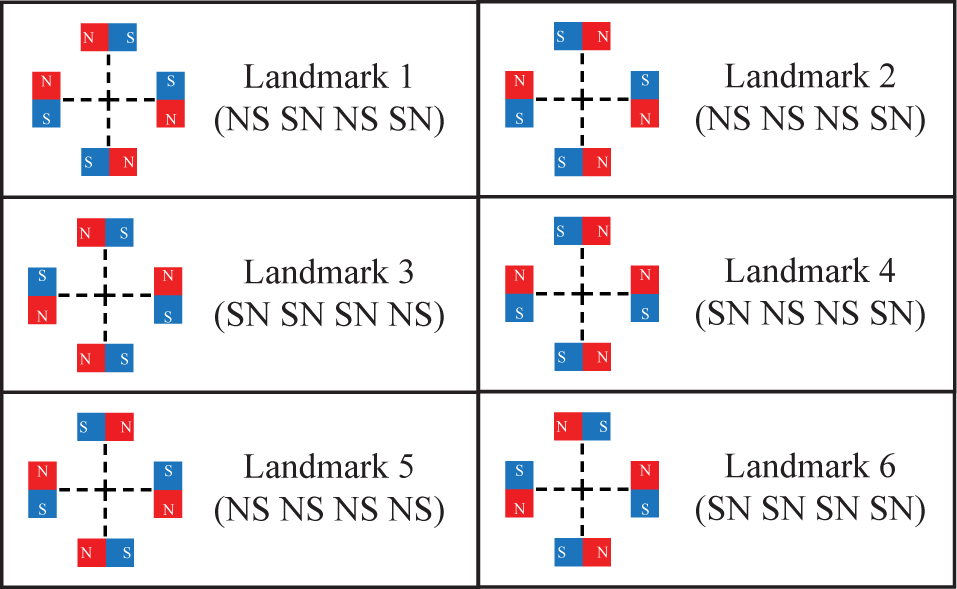
Illustration of magnetic landmarks: rectangular configuration [17]. Notation starts from the polarity of the right-hand side magnet in counter clockwise direction.
A strategy for the global localization using several patterns of magnetic landmarks was introduced [19]. For finding the current position information of the robot in a global manner, the robot identifies the patterns of several neighboring magnetic landmarks and compares the measured sequence of magnetic landmark patterns with the map information. This method, however, assumes that the mobile robot is initially located or relocated in a position where the robot can recognize the pattern of the landmark, or the “landmark recognizable area”.
A motion strategy for the mobile robot to move itself from an arbitrary initial position to the landmark recognizable area is necessary. Locating the robot in the landmark recognizable area or at the geometric center of the landmark is a difficult problem for several reasons. First, finding the magnetic landmark's center is a non-convex optimization problem. Second, the local-minimum of the magnetic field does not necessarily coincide with the geometric center of the landmark because the magnetic field of some types of landmarks is asymmetrical. Furthermore, calculating the gradient of the complex-shaped landmark's magnetic field with a single sensor is time consuming and inefficient. Estimating the geometric center of magnetic landmarks which have a complex shape of the magnetic field with several isolated sensors is not a straightforward problem.
In this paper, we propose a complete solution to the localization problem using magnetic landmarks. This methodology includes a sequential landmark search technique which provides a strategy for a mobile robot to navigate itself to the magnetic landmark's geometric center from an unknown initial position. The sequential landmark search technique is merged with the local and global localization methods.
The rest of the paper is organized as follows. Section 2 provides an overview of the whole localization algorithm with pseudo-code before a detailed explanation. Section 3 describes the sequential landmark search technique to find the landmark's geometric center using the sensor measurement of the asymmetric landmark's magnetic field strength and shows the simulation result of the proposed methodology to verify its usefulness and completeness. In Section 4, we provide a summary of the pose error compensation(tracking) and the global localization method using magnetic landmarks for the sake of completeness of the methodology. Section 5 describes the environment where the proposed technique is applied and provides experimental results. Finally, the paper is concluded in Section 6.
2. Overview of the Localization Algorithm
In this section, an overview of the whole localization algorithm is explained with pseudo-code, as shown in Figure 2. When the mobile robot is initially located or relocated at an arbitrary position, it does not have any information about its current position. Therefore, the robot runs the sequential landmark search technique to find the geometric center of the first encountered landmark. Then, the robot can recognize the pattern of the landmark, the robot is in the landmark recognizable area, because all of the hall sensors are positioned above the magnets of the landmark by using the sequential landmark search algorithm. This algorithm is fully explained in Section 3.

Pseudo-code of the whole localization algorithm using magnetic landmark
Once the robot recognizes any landmark, the position tracking can be done using the pose error compensation(local localization) algorithm. When the robot enters the landmark recognizable area using the sequential landmark search, it rotates at the geometric center of the landmark to measure the magnetic field strength through hall sensors attached on the bottom and converts the sensed signals to the distance value from the magnet's center to the robot. Then, the robot can compensate the pose error between the landmark's center using this local localization algorithm. More detailed explanation is described in Section 4. A.
The robot stores the recognized landmark information in the ‘Landmark Stack’ which is a memory stack that is built for global localization. After collecting several pieces of neighboring landmark information, the global localization algorithm compares the distribution of neighboring landmarks' patterns with the global map. Finally, the global pose information of the robot can be obtained. In Section 4. B., this global localization method is introduced in more detail.
3. Sequential Landmark Search Technique
In this section, the sequential landmark search technique is proposed to find the geometric center of magnetic landmarks. The sequential landmark search technique generates circles with geometric information of the landmark's magnetic field and uses those center coordinates of the circles for the initial approaching direction of the robot to the landmark. After finishing the initial approaching phase, the robot estimates the precise location of the center of the landmark using measured valleys of the landmark's magnetic field. Reconciling the heading direction of the robot with the valleys can be done afterward.
3.1. Shape of landmark's magnetic field
The typical shape of the landmarks' magnetic field is depicted in Figure 3 and Figure 4. In the ‘Mountain’ area, the magnetic field is stronger than that of the neutral area. In the ‘Neutral Magnetic Valley(NMV)’ area which is surrounded by the ‘Mountain’ areas, the magnitude of the magnetic field strength is neutral. In the ‘Plain’ area, which surrounds the ‘Mountain’ areas, the magnitude of the magnetic field strength is neutral. In the ‘Gulf’ area, the magnetic field of the landmark is dented toward the center of the landmark along the NMVs.
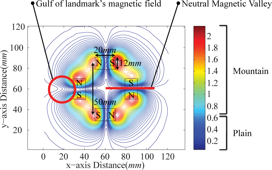
Absolute value of the hall sensor about the magnetic landmark 1
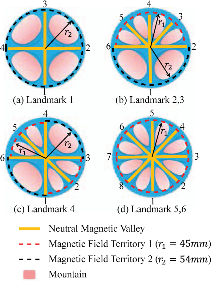
The magnetic field's radius, the NMV and the Mountain division of magnetic landmarks
In this work, we make a simplified geometric model of the landmark's magnetic field to facilitate the motion strategy of the mobile robot. The magnetic field is normally composed of two semicircles (except for the gulf area). The area where the polarity of the magnet is alternating, such as NS or SN, corresponds to the first semicircle with a radius of r1 = 45mm, and the area where the same polarities are facing each other, such as NN or SS, corresponds to the second semicircle with a radius of r2 = 54mm. As described in Figure 4, each magnetic landmark has its own unique arrangement of ‘Mountain’, ‘Plain’ and NMV areas. The two radii(r1, r2) are the values of the minimum standard deviation between ‘Mountain’ and ‘Plain’ boundaries. The magnetic landmarks have four distinguishable types of NMVs as shown in Figure 4. The angle between NMVs which are lying on both sides of a ‘Mountain’ in an area where the polarity of the magnet is repeated(NS or SN) is 45°. The angle between NMVs which are lying on both sides of a ‘Mountain’ where the same polarities are facing each other(NN or SS) is 90°.
The mobile robot needs to extract the center of the landmark from the geometric information. The extracted information is depicted in Figure 3, which depicts the coordinates of the magnetic field territory's enter points(MEPs) and the distance between local minimum-maximum points of the landmark's magnetic field. When the mobile robot passes through a magnetic landmark, it collects output voltage data from the hall sensors. Then, the robot finds the coordinates of MEPs which are not located in the gulf area and the distance between the local minimum-maximum points of the collected data.
3.2. First step: approaching inside of the landmark
The first step of the sequential landmark search technique uses coordinates of MEPs, two radii(r1, r2) and the distance between local minimum-maximum points of the magnetic field. The mobile robot gathers the information of MEPs while moving through the magnetic landmarks. After eliminating coordinates of MEPs which are located in the gulfs of the landmark's magnetic field, the robot finds the appropriate point to enter the landmark with remaining MEPs and two radii(r1, r2). The detailed procedure of the first step of center estimation is described below.
There are two cases when the first step of the sequential landmark search technique is carried out. The first case is when the mobile robot collects more than 4 points of MEPs, and the second case is when the mobile robot collects only 2 points of MEPs. When the number of MEPs is more than 4, the mobile robot calculates the coordinates of the MEPs after collecting the changes in hall sensor voltage data while moving through the magnetic landmark. Then, the mobile robot computes every circle that can be generated with the MEPs and two radii (r1, r2). The each center of each circle could be useful for the robot to enter the landmark. After generating the circles, the robot eliminates the circles whose center coordinates are located outside of the convex hull of MEPs. Finally, the average coordinates of the centers of the remaining circles are used as the first step of estimation of the center of the landmark.
When the number of MEPs is 2, the robot finds four circles with two coordinates of MEPs and two radii (r1, r2). However, eliminating two coordinates farther from the center of the landmark than the others is possible by using the information from the hall sensors after having encountered the magnetic field. For example, if one of the hall sensors attached on both lateral sides of the mobile robot passed through the magnetic field of the landmark, the two center coordinates of circles which are closer to the robot's center would be the outside of the landmark. Therefore, they are neglected and the robot uses the average coordinates of the centers of the remaining circles as the first step of estimation of the center coordinates of the landmark.
However, because of the gulfs of the landmark's magnetic field, the assumption that the shape of the landmark's magnetic field is composed of two semicircles contains an error. Therefore, the coordinates of MEPs which are in the gulfs of the magnetic field territory are excluded while the mobile robot estimates the first step of estimation of the center coordinates of the landmark. When the coordinates of MEPs are collected from locations that do not satisfy a threshold, tG = 5mm, apart from NMVs, these entry points are in gulfs of the magnetic field territory. The distance between local minimum-maximum points of the hall sensor output voltage data when passing through the gulf of the magnetic field territory is d1 = 50mm ± 10mm, as shown in graph (2) in Figure 5. The other cases show that the distance between local minimum-maximum points of hall sensor output voltage data is d2 = 20mm ± 10mm, as shown in graph (1) and (3) in Figure 5. In short, it is possible to distinguish whether the MEPs are in the gulf of the magnetic field territory or not. The MEPs which are detected in gulfs of the magnetic field territory are neglected while estimating the landmark's center coordinates to overcome the situation when the shape of MEPs is a non-convex.

Coordinates of magnetic field territory's entry points and the distance between local minimum-maximum points of the magnetic field when the mobile robot passes through the center of the magnetic landmark3
3.3. Second step: precise center estimation
If most of the first step estimation results are not located in the landmark recognizable area, the robot tends to fail in recognizing the landmark after rotating at the first step estimation center. So, as a second step, we go through a precise center estimation step which uses NMVs to recognize the landmark and to estimate the precise coordinates of the landmark's center.
After the mobile robot moves to the first step of the estimation result, it proceeds with the second step landmark center estimation method using NMVs. After collecting the coordinates of cross points between NMVs and the circle of hall sensors while rotating, the mobile robot selects 4 cross points where the lines drawn from the points facing each other are perpendicular such as points 1′, 2′, 4′ and 6′ of Figure 6(b). The cross point of the NMV and the circle of hall sensors is denoted by the label number of the magnetic valley with the prime symbol. For example, the cross point of NMV 1 and the circle of hall sensors is labeled as 1′ in Figure 6(b). Using cross points, the second step landmark center can be estimated. The detailed procedure is explained below.
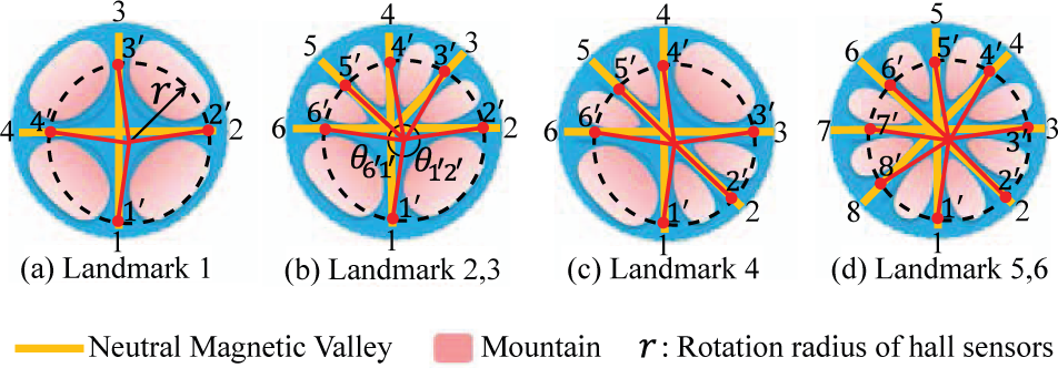
Illustration of the cross point between hall sensors' rotation radius and the NMV on each landmark
The first procedure of the second step of the center estimation is to recognize the landmark. The mobile robot uses the number of cross points and the angles between neighboring NMVs to recognize the landmark. As shown in Figure 6(a), the characteristic of landmark 1 is that there exist only four cross points between NMVs and the circle of hall sensors. In the case of landmarks 2 and 3, there are a total of six cross points and two large angles between the bottom two neighboring NMVs as shown in Figure 6(b). Landmark 4 has six cross points and two large angles in the first and the third quadrants, as shown in Figure 6(c). Finally, landmarks 5 and 6 have eight cross points between NMVs and the circle of hall sensors, as shown in Figure 6(d). Using NMVs, landmarks can be classified into four types.
These four types in Figure 6 are defined by the magnetic field strength in an absolute scale. Once the polarity is encountered, six landmarks can be distinguishable [18]. However, if the change in the hall sensor's output voltage is used, then the robot must be located in the landmark recognizable area. On the other hand, the proposed recognition method using NMVs in this work can recognize and estimate the landmark center while the robot is away from the center of the landmark and does not require the robot to be in the landmark recognizable area.
After recognizing the type of landmark, the mobile robot labels each cross point and finds the precise coordinates of the landmark's center. In the case of landmark 1, because it has only four NMVs, labeling is obvious as shown in Figure 6(a). In the case of the landmarks 2 and 3, the cross point of the NMV that exists between two large angles is set to 1 ‘. The other cross points are labeled 2′, 3′, ⃛, 6′ in the counter clockwise direction and the cross points 1′, 2′, 4′ and 6′ are used to estimate the center of landmark, as shown in Figure 6(b). In the case of landmark 4, the cross point 1 ’ is on the right side of the large angle of neighboring NMVs. The other cross points are labeled in the same as in the previous case. To estimate the center of the landmark, the cross points 1′, 3′, 4′ and 6′ are used as shown in Figure 6(c). In the last case for the landmarks 5 and 6, four non-neighboring cross points are used to estimate the landmark center because the landmarks 5 and 6 have a total of eight NMVs. After the cross point labeling procedure is over, the mobile robot computes the cross point of two lines which are drawn from each cases' two pairs of facing cross points, such as
The result of the second step is the geometrical center of the landmark. The result may have some variations because the magnetic field strength of each magnetic bar is not identical. However, it is experimentally verified that the effect of the magnetic field's variation is very small and negligible. Further discussion can be found in Section 5.
3.4. Third step: locating all of the hall sensors on the magnetic bars
After completing the second step, the mobile robot has to ensure that all the hall sensors are located above the magnets of the landmark. This is a requirement for the mobile robot to proceed with the local localization and pose compensation method. Therefore, the pose angle compensation method for reconciling the robot's heading direction to the NMVs was developed.
The mobile robot calculates the relative heading direction from NMVs and compensates the pose angle to locate all the hall sensors above the magnets. After moving toward the estimated landmark center, the robot recognizes the type of the landmark and finds the cross points while rotating 360°. Then, the robot calculates the angles between its heading direction and NMVs which are located along the center of the landmark and the magnet such as NMVs (1), (2), (4) and (6) of Figure 7(b). Then, the robot reconciles its heading direction to one of NMVs, which has the minimum value among calculated angles. After locating all the hall sensors above the magnet of the landmark, the landmark search procedure ends with success.

Position and Pose angle compensation using NMVs, (a) Position compensation, (b) Pose angle compensation
When the hall sensors are located on the magnetic bars, the robot can estimate its pose with respect to the geometric center of the landmark using hall sensor information [18]. At this point, the hall sensor output voltage is linearly proportional to the distance from the center of the magnet in the longitudinal direction of the bar magnet. Also, the robot recognizes the pattern of the landmark. With both the hall sensor output voltage and the recognized pattern information, the robot can calculate its pose error and compensate the error.
3.5. Simulation on first landmark center estimation
To prove the completeness of the sequential landmark center estimation method, intensive simulations were carried out. The simulations include every possible situation when the mobile robot encounters magnetic landmark 3, for which it is the most difficult to estimate the center because of its asymmetric configuration.
3.5.1. Simulation setup
In the simulations, 360 starting points on a circle of radius r are given as initial conditions to the robot, as shown in Figure 8(a). The radius r is set to 115mm to place all the robot's hall sensors outside of the landmark's magnetic field. Additionally, the simulation program runs 91 heading directions for each starting point. These heading directions are from −45° through 45° where 0° is the direction when the robot heads toward the landmark center. The total number of the simulated initial conditions is 32,760 which include the cases when the robot does not go through the region of the magnetic field. These cases are ruled out by the sequential landmark center estimation method.

Setup and result of the MATLAB simulation of the sequential landmark center estimation, (a) simulation setup, (b) result of simulation
3.5.2. Simulation result
As shown in Figure 8(b), the simulation result (the average distance from the landmark center is 7.28mm, the standard deviation is 3.53mm, and the maximum distance from the landmark center is 17.9mm) shows that all of the estimated centers are inside of the boundary line (a red circle in Figure 8(b)). Therefore, the second step can be carried out successfully. The successful base line of the first step of landmark center estimation which is 20mm depends on the size of the circle of hall sensors whose radius is 25mm with a 5mm margin. As a result of the simulation, it is empirically verified that the sequential landmark search technique finds the center of the landmark from any possible initial position.
4. Tracking and Global localization
In our previous research, tracking and global localization techniques have been introduced [18], [19], and they are briefly summarized in this section for the sake of completeness of the work. The methods are used for a mobile robot to navigate itself after performing the sequential landmark search technique.
4.1. Pose error compensation (Local localization)
Four magnetic hall sensors are attached on the bottom of the mobile robot platform and are used to measure the potential difference to be transformed to a distance value from the center of the magnet to the center of the hall sensor [18]. When the hall sensor is located above the magnetic bar, the output voltage of the hall sensor is linearly proportional to the distance between the hall sensor and the center of the magnetic bar. This set of measurements can be used as a single axis of the coordinate system. The type of the landmark and the local pose error are recognized with these measured potential differences. Using this local localization information, the robot can compensate the pose error between the center of the landmark more accurately than other artificial landmark-based localization methods [17].
Also, the mobile robot can compensate its current pose error not only on the present landmark, but also while moving to the next landmark using a landing curve [32]. A landing curve is composed of two constant-radius circular arcs to generate a path for the robot to compensate its position error while traveling toward the next landmark.
4.2. Global localization
The strategy for global localization using several patterns of magnetic landmarks is explained and summarized in this section. More detailed information can be found elsewhere [19]. Once the robot identifies the pattern of the current landmark, position tracking is easily achieved with the pose error compensation method. After this, globally localizing the mobile robot is also possible.
When the pattern of the magnetic landmark of the current location and the neighboring patterns are sequentially identified without any prior knowledge, the robot compares the measured sequence of patterns with the grid-like global map to complete the global localization. For example, the mobile robot obtains the current global coordinate information using an ‘L’ shape magnetic landmark pattern which is composed of three neighboring landmarks. In addition, the performance of the proposed global localization method depends on the distribution of magnetic landmarks. Detailed information on distribution problem of landmarks can be found in our previous research [19].
5. Experimental Evaluation
In this section, the performance and the effectiveness of the sequential landmark search, tracking and global localization methods are evaluated through experiments. The three methods are combined into a complete localization technique and applied to a mobile robot.
5.1. Environment
The experimental environment is composed of a test-bed with magnets, small mobile robots were designed and fabricated, as shown in Figure 9 and Table 1. The mobile robot is a differential-drive type, and four hall sensors are attached to the bottom of the mobile robot. Data transmission between the mobile robot and a main computer is realized with the Bluetooth communication protocol. The workspace of the mobile robot is restricted to the test-bed where magnetic bars are embedded and arranged for landmarks on the surface. One set of magnetic landmarks is composed of four magnetic bars.

Illustration of the small-sized mobile robot and example of global localization in experimental environment
Specification of the mobile robot and the landmark

5.2. Experimental Results
In this section, the first step of the landmark center estimation method using MEPs is performed and the results are discussed. Then, the second step using NMVs is conducted, and the final results of the estimation of the landmark's center is interpreted. The effect of the magnetic field's variation is also discussed. Finally, the localization technique including the sequential landmark search, tracking and global localization methods is evaluated as a complete localization algorithm.
5.2.1. Experiment on the first step landmark center estimation method using MEPs
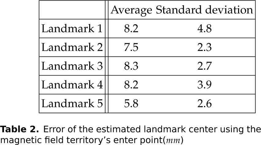
In this experiment, a mobile robot which does not have any prior knowledge about its location attempts to estimate the center of the landmark with the first step of the landmark center estimation method using MEPs. To confirm the accuracy of the first step, experiments are is performed ten times on each landmark. The robot is set at fifty arbitrary starting points for the experiments. As shown in Table 2, all of the distances between estimation points and the center of the landmark are less than 20mm. This means that all the first-step estimation results are in the area where the second step of center estimation can be performed successfully.
Error of the estimated landmark center using the magnetic field territory's enter point(mm)
5.2.2. Experiment on the second step of the landmark center estimation method using NMVs
The second step of landmark center estimation is examined to verify the estimation method that uses NMVs to find the landmark's center. This is carried out on the estimated center from the first step of center estimation. As shown in Figure 10 and Table 3, most of the estimation results are less than 3mm away from the center of the landmark. In other words, the robot can enter the landmark recognizable area using the first and the second landmark center estimation method sequentially. Although some estimation landmark centers are farther than 6mm from the center of the landmark, like in one case shown in Figure 10(c), this problem can be overcome by retrying the second step of landmark center estimation.
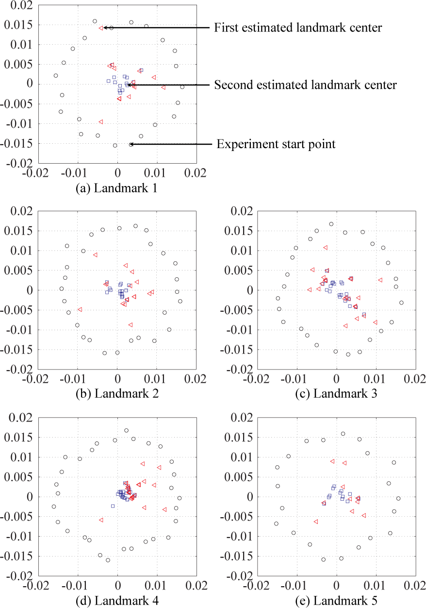
Experimental result of the landmark center estimation using NMV(m)
Error of the estimated landmark center using the NMV(mm)

5.2.3. The effect of the magnetic field's variation
This experiment was set up to investigate the effect of the magnetic field's variation on recognizing the landmark with NMVs. To see the effect of the magnetic field's variation, 10 landmarks for each of 5 kinds of landmark configurations (landmark 1 through 5) were built (in total 50 magnetic landmarks) and the magnetic strength of each case was measured with hall sensors. The mobile robot is initially located on the center of these landmarks and attempts to recognize the landmark using NMVs, as mentioned in Section 3. Experimental results of the influence of the magnetic field's variation are illustrated in Figure 11.

Illustration of the effect of the magnetic field's variation experiment
Even when including the standard deviation of the results, the differences among measured angle values between neighboring NMVs are big enough for distinguishing each NMV. Therefore, the magnetic field's variation of the magnets has no significant effect on recognizing the landmark using NMVs.
It has been experimentally verified that distinguishing each NMV of the landmark is possible. Also, it is feasible to specify the NMVs which are located along the center of the landmark and magnet, such as the NMVs (1), (2), (4) and (6) in Figure 11(b). The mobile robot which arrives at the landmark's center using the sequential landmark estimation technique can recognize the landmark and find the NMV which is the nearest to the heading direction of the robot and lying along the center of landmark and magnet. Finally, the robot can locate all the hall sensors on top of the magnets. This allows the robot perform local localization, pose error compensation, and global localization
The mobile robot performs the sequential landmark center estimation, the landmark recognition-pose angle compensation using NMVs and the pose error compensation using the change of the hall sensor's output voltage continuously, with which it can locate itself at positions less than 1mm away from the geometric center of the landmark with heading direction less than 1.5° away from the nearest NMV.
5.2.4. Experiment on localization for arbitrary initial positions
In this experiment, the mobile robot is placed on a set of arbitrary positions without any prior knowledge about its position and localizes itself in global coordinates with the localization technique. From the starting point, the robot uses the first step of the landmark center estimation method (Steps 1-3) using coordinates of MEPs and the second step of the landmark center estimation method (Steps 4-7) using NMVs continuously to estimate the landmark's center. Then, the global localization method (Steps 8-16) using three collected neighboring magnetic landmarks' information is performed to obtain the global pose information. Figure 12 shows an example of the localization experiment using the algorithm. It is noted that the algorithm is not optimized at this point. By increasing the robot's speed, or improving the motion strategy for the pose error compensation, the execution time for global localization can be further reduced. Also, it is noted that such a global localization is normally performed one time when the robot is initially deployed.

The steps of localization. The robot uses the first step landmark center estimation method, the second step landmark center estimation method using NMVs and the global localization method which uses three collected neighboring magnetic landmarks information continuously to get the global pose information from an unknown initial position. (a) move forward until contacting the magnetic field, (b) collect magnetic field data while moving forward, (c) estimate first-step landmark center and move to the point, (d) attempt landmark recognition while rotating, (e) compensate position error with NMVs, (f) determine rotation error with NMVs, (g) compensate rotation angle to position compensation possible angle, (h) recognize and save first landmark, (i) compensate position error on the first landmark, (j) move to second landmark, (k) recognize and save Second landmark, (l) compensate position error on the second landmark, (m) rotate 90 degrees to move to third landmark, (n) move to third landmark, (o) recognize and save third landmark, (p) compensate position error on the third landmark and localize with information of three neighboring landmarks.
6. Conclusions and Future Works
In this paper, a complete localization method including a sequential landmark search technique, a tracking and a global localization method for magnetic landmarks has been presented. The sequential landmark search technique provides a strategy for a small mobile robot to estimate the geometric center of the magnetic landmark using the shape of the neutral boundary line and valley arrangement of the landmark's magnetic field while the current pose of the robot is unknown. The proposed sequential landmark search method is developed to place the robot from an arbitrary initial pose on to the area where the robot recognizes the pattern of the magnetic landmark. The sequential landmark center estimation method uses the change of the hall sensor's output voltage and shape information of the landmark's magnetic field to search for a landmark. Then, the proposed sequential landmark search method is unified with the tracking and the global localization methods to be a complete localization technique. The experimental results show that the mobile robot can estimate the center of the landmark, place itself in the landmark recognizable area, and obtain the current pose information in the global coordinate system from an unknown initial position.
7. Acknowledgment
This research was supported by the MKE (The Ministry of Knowledge Economy), Korea, under the Next Generation Robot Actuator/Sensor Research Center support program supervise by the NIPA (National IT Industry Promotion Agency) (H1502-13-1001).