
Abstract
This paper presents an Internet remote control interface for a MITSUBISHI PA10-6CE manipulator established for the purpose of the ROBOT museum exhibition during spring and summer 2004. The robotic manipulator is a part of the Intelligent Robotic Systems Laboratory at Heriot – Watt University, which has been established to work on dynamic and kinematic aspects of manipulator control in the presence of environmental disturbances. The laboratory has been enriched by a simple vision system consisting of three web-cameras to broadcast the live images of the robots over the Internet. The Interface comprises of the TCP/IP server providing command parsing and execution using the open controller architecture of the manipulator and a client Java applet web-site providing a simple robot control interface.
Introduction
Tele-operation applied to robotics vastly enriches the range of applications. One can find examples in space, underwater, dangerous environments (power plants), and medicine. Due to the intense development of the Internet, it can nowadays act as a medium connecting many locations (in different countries) using one single protocol. The availability of the Internet and its side tools also allows one to present recent technological developments in a popular and easy to use manner.
The subject of robotic tele-operation has been widely studied and a survey can be found in (Taylor and Dalton, 2000), also describing an available public implementation of an Internet robot controller. Another interface enriched with force feedback data can be found in (Oboe, 2001). One of the first industrial arms made available on the World Wide Web is presented in (Goldberg et al., 2000). Another system, presented in (Park et al., 2004), performs real-time control of an Internet robot. Although there are some tele-operated robots available on the Internet, the authors have not encountered any available interface for Mitsubishi PA10-6CE.
In this paper an Internet based remote control system for a robot with visual feedback is presented. The interface was designed for the purpose of a robotic exhibition and is therefore aimed to be self-explanatory and safe. The basic idea of the system is to share a real robotic arm with a wide audience for interaction and educational purposes 1 .
The following elements of the system can be distinguished (Figure 1):
the manipulator with an open controller architecture, the network server / robot controller PC, the vision system, the Internet, any computer with Java enabled web-browser, the user.
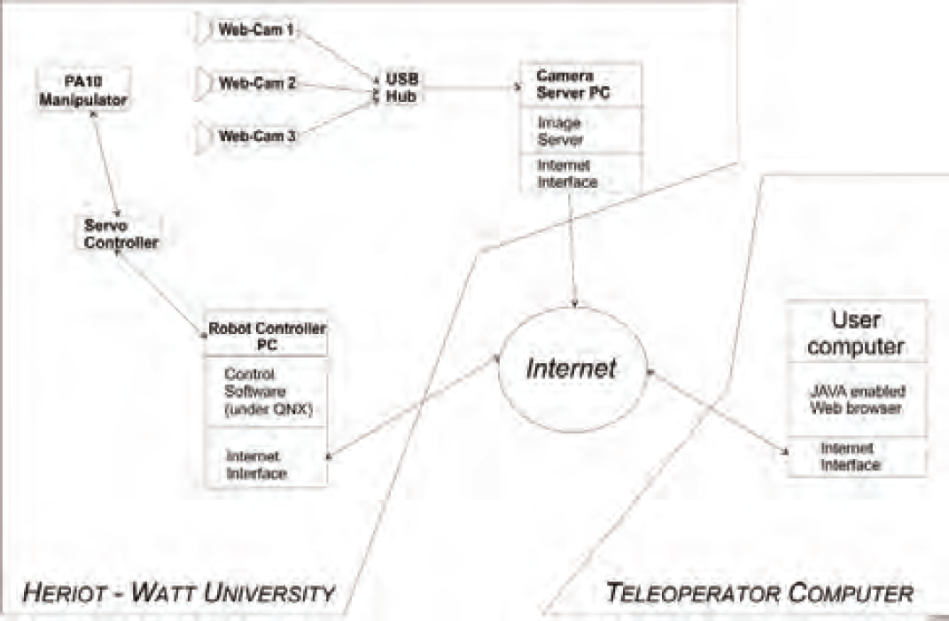
A schematic showing the components of the system and the communication paths
The paper is organised as follows. The first section introduces the basic ideas and background of the tele-operated system. The second section deals with the server implemented within the robot control application. A brief description of the vision system is given in section three. In the fourth section the client side of the software is presented, together with the graphical user interface. Section five describes some hurdles met and overcome while the system was operational during the exhibition and ideas for further work.
The Mitsubishi PA10-6CE robot is characterised by an open controller architecture, which means that the control layer for the robot can be replaced and freely manipulated. This allows the user to develop and test any desired dynamic controller for the robot. A system had already been developed for the purpose of controller testing in the robotics laboratory at Heriot-Watt University. In order to adapt it to create a robot control server, a network communication module had to be added. In order to provide target setting, a simple path planning algorithm has been included. The kinematic transformations module needed to be programmed to allow Cartesian control and collision avoidance with the static elements present in the environment was also developed.
The control application
The API and drivers required to interface the robot were previously developed (Uhlmann, 2003). They provide a simple and flexible interface for programming the manipulator by sending desired joint torques, the manipulator replies with its state (positions, velocities, applied torques). A high level control application has been created on top of this system, with the following key upgrades:
forward and inverse kinematics path planing (smoothing) safety features.
The control application algorithm is presented in Fig. 2.

A schematic showing the control application algorithm
In order to determine the position and orientation of the end-effector of a manipulator in Cartesian space (based on the joint angle positions), the forward kinematics is required. To perform the inverse task, which is used in Cartesian position control of the manipulator end-effector, the inverse kinematics is used. The forward kinematics can be computed by means of matrix algebra based on the Denavit-Hartenberg algorithm (Craig, 1986). The inverse kinematics algorithm employed in the control application is a modification of the algorithm developed by T. Scherer (Scherer, 1999).
Path planning
In order to obtain smooth motion of the arm, a path planning algorithm based on 3-rd order polynomials has been implemented (Craig, 1986).
The following assumptions have been made (for both joint and resolved control)
target position is given by the user initial position and velocity are sampled immediately after giving a target position target velocity is set to zero motion time is calculated based on a scaling velocity

Schematic of manipulator joints (with names)
The robot must be prevented from colliding with known static objects in its workspace. One can cover the forbidden space with boxes (eg. one for the base, one for the table, and one for the cables connected to the robot). A simple algorithm based on the forward kinematics checks whether the elbow, wrist or end-effector of the manipulator are about to enter into one of the defined forbidden boxes in the next sample / control step and prevents the arm from any further motion until it moves away from the forbidden area.
The server
The robot control application has to handle all the network commands (listed later in this section), kinematics calculation, path smoothing and robot safety operations. All the control functionsmust be synchronous as they are required at each sample step (at the rate of 500Hz), the communication however should be asynchronous, and separated from them (for practical and security reasons). The QNX operating system supports threads, which enables a simple solution. The network server is a thread which communicates with the control thread via a global data structure. A single variable accessed from both routines has been used for the state machine register. Whenever a new target position is given, the state changes. When the control thread enters its next iteration, this new state is processed in order to obtain new trajectory parameters and start following it. The variable defines one of the following states
NO CTRL - maintaining the present position, JOINT CTRL - moving to a new joint position, KIN RPY CTRL - moving to a new Cartesian position with orientation expressed in Roll, Pitch, Yaw angles, KIN EULER CTRL - moving to a new Cartesian position with orientation expressed in Euler angles, RANGE ERROR - out of range, stopped, PROG EXEC - a predefined program is executing.
Once the RANGE ERROR state is reached, the user should send a command to move the arm to its default position (all joints set to zero).
The following network commands are accepted by the network server
j nn (×6) set new joint positions, k pp (×3) nn (×3) set new Cartesian positions and RPY orientations, w query the state of the manipulator controller, the reply can be either a – awaiting new commands, e – error, b – busy, W server thread will wait while the arm moves, p nn execute the nn-th program from a file, g nn open nn=0 or close nn=1 the gripper.
The server thread algorithm is presented in Figure 4(a).
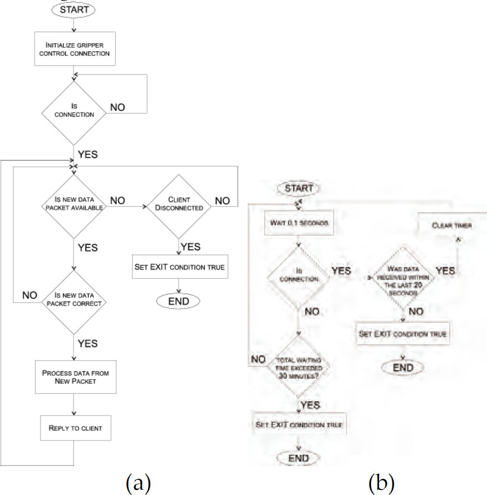
A schematic showing (a) the network server thread and (b) network watchdog algorithms
The network connection is vulnerable and if the client loses the connection, the server has to detect it. Therefore due to network vulnerability a watchdog is required to monitor the network state. A separate thread monitors the network activity (or inactivity) and restarts the control application whenever there is no communication for a certain period of time. It also checks if a connection has been established at all, and if not it times out after a given period. This action is targeted at network anomalies at the server side. These features increase the robustness of the system (while working unmanaged for long periods of time). The algorithm is presented in Figure 4(b)
Program execution
A separate routine runs predefined programs from a file. The commands correspond with the network commands. The routine is called by the network thread upon receiving a viable program execution command. The manipulator is in a busy state while the program is executing.
Vision system
A commercial package has been used for the web–cam server application
2
, running on a Celeron 2GHz CPU with Windows 2000. The images are captured and broadcasted with resolution 320times240 at 5 frames per second. The software was supplied with a simple Java client for viewing the live camera image which can be easily incorporated into a web-page. The subsequent cameras show
the robot with its surroundings, the table on which objects can be manipulated, the view from the gripper.
Client applet
In order to send commands to the manipulator, one can either connect in a terminal mode, or use a user friendly front-end application. A simple Java applet has been developed for that purpose. This applet has been incorporated into a web-page together with the vision system client applets to provide a simple and natural control interface.
Communication
The communication layer in the client consists of a control commands transmission routine and a network connection watchdog thread. The user interface collects data from the user and transforms it to a control packet passed further to the server over the Internet. The watchdog thread assures that the connection is live, otherwise it notifies the user interface layer to disable all controls, until the connection is re-established.
Graphic user interface
The client interface provides the user with three control modes.
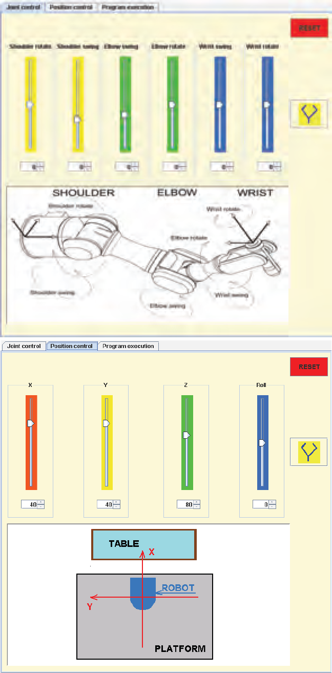
Joint and position control tabs in the user applet
Both
An engineering project made for general public use always involves a vast amount of user feedback and practical changes during the lifetime of the exhibition.
Practical observations
The biggest problem encountered during the exhibition, was the network speed on the client side. The connection was often lost, therefore the network watchdogs have been introduced, which improved the robustness significantly. Due to wide manipulation range of the manipulator joints, the cables connecting the signals for the camera and the gripper were often twisted and strained, therefore extra bounds were introduced to prevent it. A log file was created to compensate for the incomplete supervision of the laboratory. It allowed one to analyse the times of connection drops and their reasons. It appeared that mostly during lunchtime the connection was lost and regained several times during the hour.
Conclusions
The system has been tested with the general public (museum visitors) and after some improvements (especially in the network connection layers) proved to work satisfactorily. The network speed on the client side proved to be much slower on average than a home broadband line. The network delays could also be interpreted as disturbance arising from very long distances (space applications).
The ROBOT exhibition, which featured the robot Internet link described in this paper, was extremely successful and resulted in significant positive exposure for Heriot-Watt University. During its running period, it attracted over 25000 visitors, among them many school-children raising their Science and Engineering awareness. Significant media exposure resulted with national TV and radio items featuring the exhibition, together with several press articles (Herd and Dunnigan, 2004), (Cuddidy, 2004).
Further work
Extra features planned to be implemented include:
allowing for user defined programs, username authentication to increase security, publish the system to search engines, allow for position and velocity setting commands.
Footnotes
Acknowledgements
The authors would like to thank QNX for providing to us the QNX Neutrino PE real - time operating system.
1
The connection has been presented in the ROBOT exhibition at Callendar House, Falkirk, Scotland (as a joint venture between Heriot-Watt University, EPSRC (Engineering and Physical Sciences Research Council) and the Falkirk City Council).
2
Active WebCam Pro from PYSoftware, providing multiple camera support and a HTTP server.