
Abstract
In this paper we report on the design, modeling, experimental testing and scaling analysis of a novel MAgnetic Variable stiffnEess spRIng-Clutch (MAVERIC) device, which may be used as the elastic element of Variable Stiffness Actuators (VSAs). The device, comprising two co-axial diametrically magnetized hollow cylinders, has two degrees of freedom: a rotation of the two cylinders around the common axis and a relative translation along the same axis. For small rotations, the torque arising from the magnetic interaction of the two cylinders is almost linearly proportional to their relative rotation, as in mechanical torsion springs. In addition, the stiffness of the equivalent spring can be varied continuously from a maximum value down to exactly zero by changing the axial overlap of the two cylinders. In this way the proposed device can be used both as a clutch (i.e., perfectly compliant element) and as a variable stiffness torsion spring. A prototype, designed after magnetostatic FEM simulations, has been built and experimentally characterized. The developed MAVERIC has an experimentally determined maximum transmissible torque of 109.81mNm, while the calculated maximum stiffness is 110.2mNmrad−1. The amplitude of the torque-angle characteristic can be tuned linearly with a sensitivity of 12.63mNmmm−1 rad−1. Further simulations have been computed parameterizing the geometry and the number of pole pairs of the magnets. The maximum torque density reached for one pole pair is 47.21 · 103 Nm m−3, whereas for a fixed geometry similar to that of the developed prototype, the maximum torque is reached for seven pole pairs. Overall, compared to mechanical springs, MAVERIC has no fatigue or overloading issues. Compared to other magnetic couplers, torsion stiffness can be varied continuously from a maximum value down to exactly zero, when the device acts as a disengaged clutch, disconnecting the load from the actuator.
1. Introduction
Compliant transmissions, equipped with sensors providing a feedback on the output torque, are used in a number of robotic applications. Examples include robotic hands, where the elastic elements are used to perform a stable grasp [1–3], flying robots, in order to estimate the pitch torques generated by wings during flapping [4] and robotic snakes, for estimating ground contact forces [5]. Furthermore elastic elements are key components of Series Elastic Actuators (SEAs) [6–9], Variable Stiffness Actuators (VSAs) [10–18] and, more generally, of Variable Impedance Actuators (VIAs) [19], where damping can also be adjusted by properly controlling the device. In this field, a seminal work is that of Fasse et al. [20], where an electromagnetic variable impedance actuator is demonstrated, capable of exerting a torque much higher than that of the prototype described in this paper.
SEAs, VSAs and VIAs are usually composed of one or more actuator (pneumatic, hydraulic, electric), possibly embedding gearboxes, compliant transmissions and sensors measuring the deformation of the elastic elements [21]. Elastic elements are also used in compliant joints [22–28] as they are particularly useful in terms of intrinsic safety, as in the case of wearable robotics, or to tune the dynamical properties of the robot, as needed to establish an effective interaction with the environment and the wearer [29]. Elastic elements also provide the mechanical structure with the capability to efficiently store and release mechanical energy. This feature is particularly useful for the generation of oscillatory movements. Moreover, the elastic energy stored in compliant elements can be quickly released for fast operations.
In the development of SEAs and VIAs, the often conflicting main design requirements are: compactness, lightness, backdrivability, compliance adjustability, maximum torque, torque resolution and bandwidth. Any design asks for an application-specific trade-off among such requirements. For instance, compactness and lightness are key requirements for ungrounded robots; backdrivability (either intrinsic or control-based) is important in assistive and rehabilitation robotics; stiffness adjustability is important whenever the efficiency must be optimized. Torque resolution and large torque bandwidth are also conflicting requirements, the former asking for highly compliant elastic elements to increase sensitivity, the latter asking for high stiffness to improve system response.
Several torsion springs have been proposed so far, including: linear compression springs arranged so as to produce torsion elasticity [15, 23, 24, 30]; leaf springs [13, 31]; flexible joints [22, 32–34]; custom-shaped compliant elements [7, 26, 27].
Moreover, remotely operated magnetic springs have been successfully used to operate wireless bioptic tools [35].
Magnetic couplers are a good replacement of their mechanical counterparts in a number of applications, thanks to such features as simple maintenance, high reliability, no need for lubricants, high efficiency, precise peak torque transmission, inherent overload protection, reduced drivetrain pulsations, tolerance to misalignments and low noise. Conversely, magnetic couplers are inherently characterized by a residual compliance. Nonetheless, this drawback can be managed [36] and in some applications (e.g., SEAs, VIAs) it could be beneficially exploited. Although a number of magnetic springs with constant [37–41] and variable [42] stiffness have been proposed, to the best of our knowledge no variable stiffness magnetic spring, that can also be used as a clutch, has been proposed up to now.
This paper demonstrates a synchronous one DOF magnetic coupler with diametrically magnetized permanent magnets, working as a tunable compliant torsion element, with a maximum stiffness that can be varied linearly from zero up to a maximum value. When stiffness is set to zero, the coupling behaves as an open clutch (i.e., no torque transmission).
The paper is organized as follows. Section 2 presents the concept of the variable stiffness compliant element; characterization and data analysis of the developed prototype are described in Section 3; in Section 4 a scaling analysis is presented; Section 5 presents some example applications. Conclusions and future works are discussed in Section 6.

Permanent magnets configuration in MAVERIC: magnets are concentric and diametrically magnetized. They can rotate around and translate along the z-axis. a) One pole pair magnet configuration; b) two pole pairs magnet configuration.

Configuration of permanent magnets selected for the setup. d and θ respectively are the relative linear and angular displacement of magnets along z axis. Dout1, Dout2 are the inner and outer diameter of the outer magnet, while Din1, Din2 are the inner and outer diameters of the inner magnet.
2. The concept of a magnetic variable torsion stiffness compliant element
The proposed device, in the following referred to as MAgnetic Variable stiffnEss spRIng-Clutch (MAVERIC), is a particular rotational magnetic coupler, comprising an inner and an outer part. The outer part consists of an even series of diametrically magnetized identical permanent magnets, placed in a cylindrical configuration, with alternate directions of magnetization. The concentric inner part has the same number of magnets, with alternate magnetization (Figure 1). The two nested magnetic cylinders are arranged in a two-DOF configuration, which allows the relative translation of the cylinders along the common axis and the rotation around the same axis. The axial displacement produces a change of the overlap of the two cylinders (Figure 2).
Keeping constant the magnetic properties of the permanent magnets, the stiffness can be varied by acting on the geometry of the device, e.g., by changing the thickness of the air gap between the inner and the outer parts or by varying their mutual overlap. The first solution is not only less practical from a design and fabrication point of view, but also less effective than the second one, as will be demonstrated below. Compared to the first one, the second option is not only simpler from a design point of view, but, more importantly, it allows reducing the stiffness of the coupler to zero, as needed for rendering a perfect compliance (clutch principle).
In order to demonstrate the working principle, let's consider a simple case of a rotary magnetic coupler with two nested concentric cylinders, both diametrically magnetized, so that each cylinder has one magnetic pole pair placed along the diameter (Figure 1-a). There are two main analytical approaches to derive the magnetic field from Maxwell's equations: the Coulombian and the Amperian current model [43]. Nevertheless, stiffness can be analytically calculated only in a limited number of simple cases while, in general, numerical methods are necessary. For the sake of analytically demonstrating the working principle, let's simplify the actual geometry by approximating the external magnetic cylinder (mean radius: r) to a circle (Mout in Figure 4) and the inner cylinder to a magnetic dipole (Min in Figure 4). Introducing a three-dimensional (3D) Cartesian coordinate system (x, y, z) to represent this simplified configuration, assuming the magnetization vector of the external magnet to be constant and oriented along the x axis, it is practical to describe the magnetization of the external magnet as a magnetic moment per unit length:

The magnetic moment of the inner part will have a constant module (min) and a direction depending on the rotation angle (θ):

The position of a generic magnet dipole in the external circle is:

Properties of the permanent magnets.

where z is the axial coordinate and θ1 the angular position. The magnetic flux density, due to the external magnet, can be written as [44]:
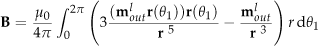
where µ0 is the vacuum permeability. Substituting (1) and (3) in (4) it is possible to derive

From (2) and (5) it is then possible to calculate the magnetic torque:

The torsion stiffness, function of θ, is:

where τz(θ) is the z component of τ. According to (7), keeping θ constant, the maximum stiffness is reached for z = 0, while stiffness becomes zero when
Although the simple model described above can be useful in shedding some light on the working principle of MAVERIC, it is too simple to provide an accurate estimate of the expected performance of a real system. Conversely, magnetostatic equations are not amenable to being solved analytically given the complexity of the geometry. Therefore, FEM simulations have been performed with the purpose of dimensioning an experimental setup. Additional simulations have been used to compute the order of magnitude of the maximum reachable torque and the storable energy density.
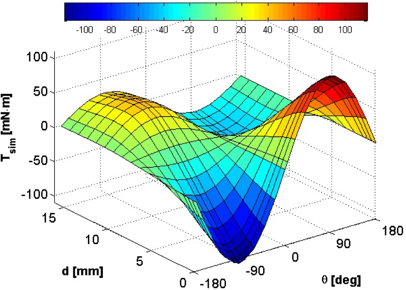
Torque simulation data in the function of magnet distance d and angle θ. Maximum torque modulus is 116.54mNm, for d = 0 mm and θ = ±90°, while d = dsim0 = 7.12mm corresponds to perfect compliance condition.
3. Characterization
The MAVERIC system taken into account features one pole pair per cylinder (Figure 2). The characteristics of the selected magnets are reported in Table 1. In the following the torque is assumed positive if it tends to rotate the inner cylinder clockwise.
3.1. Simulations
The magnet (NdFeB, HKCM engineering) dimensions and properties have been retrieved from the manufacturer's datasheet (Table 1). The selected rare-earth permanent magnets are characterized by a linear demagnetization curve and a high maximum energy product. Magnetostatic FEM simulations have been performed (Ansoft Maxwell 3D) taking into account a current free space. There are four main methods to numerically calculate forces/torques: the Maxwell stress tensor method, the co-energy method, the Lorentz force equation, and the rate of change of field energy method [45]. The selection of a specific method is usually problem-specific, although the most frequently used methods are the Maxwell stress tensor and co-energy methods. In our problem, where linear magnetic materials are considered, magnetic co-energy can be approximated to magnetic energy and forces/torques for different configurations can be calculated using the principle of virtual work. For the magnetostatic simulations, the linear and angular displacements d and θ have been taken as parameters: d has been varied from 0mm to 15.5mm (steps of 0.5mm for d ≤ 1.5mm; steps of 1mm for d > 1.5 mm), while θ has been varied from 0° to 180° (steps of 20°; in addition, θ = 90° has been simulated, since this angular position corresponds to the maximum torque). Figure 3 shows how torque depends on those parameters. In the same figure it is possible to observe the sinusoidal profile related to angular displacement. Maximum torque modulus, retrieved from simulations, is 116.54mNm, for d = 0mm and θ = ±90°, whereas perfect compliance is achieved when d = dsim0 = 7.12mm, as results from a linear interpolation.
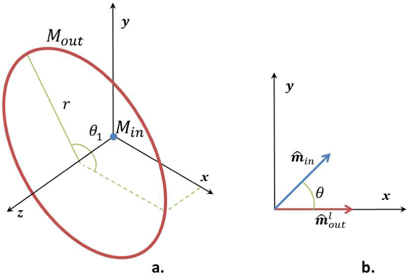
a) Simplified geometry of a rotary magnetic coupler with two nested concentric cylinders, both diametrically magnetized. The external magnetic cylinder (mean radius: r) is approximated to the circle Mout (i.e., infinitesimal thickness and height), while the inner cylinder to the magnetic dipole Min. θ1 is the angular position of a generic magnetic dipole in the circle; b) orientations of
3.2. Experiments
In order to assess the reliability of the performed simulations, an actual prototype of MAVERIC has been built, using the same materials and geometric dimensions as in the simulation. The developed prototype has been experimentally characterized, as reported below.
3.2.1. Setup
A custom measurement setup (Figure 5) has been assembled to measure torques in different configurations with a resolution of 1.0mNm. The setup comprises a linear and an angular micropositioner. The spring-loaded linear positioner allows a maximum displacement of 25.4mm, with a 1 µm resolution using the vernier scale (M-460P-X, Newport). The other positioner is a rotation stage that allows 360° of coarse and 5° of fine angular positioning: scale markings indicating every degree and vernier reading allow 5 arcmin positioning accuracy (M-481-A, Newport). Magnets have been connected to 3D-printed acrylic resin supports by means of shape coupling: a support, fixed to the rotating stage, houses the inner cylinder; the other cylinder is mounted on a shaft, supported by two ball bearings locked by two circlips in an A-shaped support, connected to the linear slide. An Al bar is fixed to the other end of the shaft. The head of a set screw in the bar localizes the contact point between the bar and the plate of a load cell (A120EC, Exacta; precision of 1 µN and a range of 1.5 N). The torque exerted by MAVERIC is calculated by multiplying the lever arm of the bar and the force read by the load cell.
3.2.2. Measurements
Exerted torques have been measured for 22 values of θ in the interval [0°, 360°], while d has been varied from 0mm to 15.5mm. Experimental data and their deviation from simulations are shown in Figure 6. In particular, the RMS error is 4.30mNm, i.e., less than 4% of the maximum measured torque (109.81mNm when d = 0mm and θ = 90°). Perfect compliance is achieved when d = dexp0 = 6.78mm. Torque-angle sinusoidal profile is confirmed by experimental data.

Overview of the experimental setup. a) CAD sketch: 1. set screw, 2. Al bar, 3. acrylic resin shaft A-shaped support, 4. rotation stage, 5. micrometer screw for angular displacements, 6. micrometer screw for linear displacements, 7. linear positioner, 8. load cell; 9. ball bearings, 10. permanent magnets, 11. acrylic resin shaft. b) Picture of the actual setup.

Torque data (experimental): a) Torque surface as a function of magnets distance d and rotation angle θ. Maximum torque is 109.81mNm, for d = 0mm and θ = 90°, while d = dexp0 = 6.78mm corresponds to perfect compliance; b) Torque surface error calculated from simulation data (RMSE =4.30mNm).
3.3. Torque fittings
The relation between maximum torque and magnet distance d in the configurations where there is overlap (0mm ≤ d ≤ 10mm) is linear (R2 = 0.994), as reported in Figure 7. It is expected that the linearity of torque-angle characteristic is advantageous in SEAs and VIAs on the grounds that a linear elastic element simplifies the actuator model and the torque control. While the maximum torque-position relation is linear, the torque-angle characteristic is sinusoidal and its profile is preserved for any value of d (Figure 8). Torque-angle characteristic for d = 0mm can also be fitted as T = b1 sin(θ) (Figure 9), with b1 = 110.20mNm (R2 = 0.999, RMSE = 1.17mNm). It is also possible to linearly approximate the torque-angle characteristic in the range ±90° (i.e. T = c1 θ) obtaining R2 = 0.920 for a torsion stiffness c1 = 79.41m Nm rad−1 (RMSE = 10.54mN m). A good analytical approximation of the torque function based on the experimental data is given by the following parametric surface (Figure 10):


Maximum torque-magnet distance profile. Experimental data are fitted with T = a1 – d a2 in the range of overlapping (d = 0mm ÷ 10mm) resulting in: a1 = 109.64mNm, a2 = 15.56N with a R2 = 0.994 and a RMSE = 4.57mNm. Perfect compliance is reached for d = dexp0 = 6.78mm..

Piecewise linear interpolations of torque-angle experimental data for different values of d. Curves preserve their sinusoidal shape also varying magnet distance d.
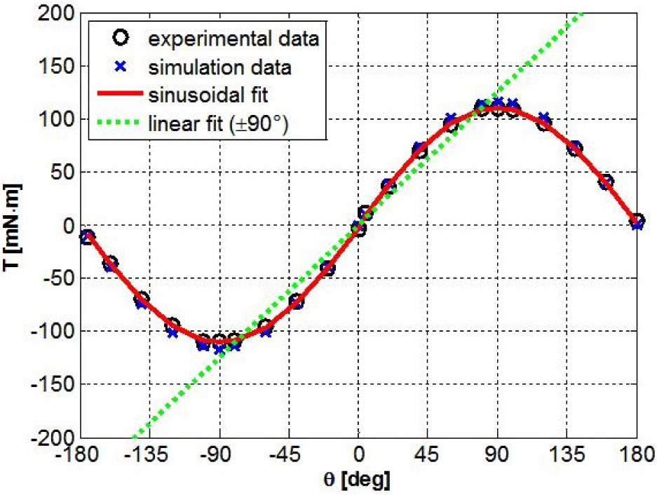
Torque-angle profile for d = 0mm. Experimental data are fitted with T(θ) = b1sin(θ). b1 = 110.20mNm (R2 = 0.999, RMSE = 1.17mNm. Experimental data are fitted also with T(θ) = c1 θ in the range ±90° obtaining a R2 = 0.920, with a RMSE = 10.54mNm and a torsion stiffness c1 = 79.41mNmrad−1.
As in the linear regression previously described, this fitting is limited to values of d within the overlap range (0mm ≤ d ≤ 10mm). When A = 102.70mNm and B = 12.63 N, one finds RMSE = 1.89mNm and R2 = 0.997.
For (0mm ≤ d ≤ 10mm), considering (8), the expected torsion stiffness is:

From (9), the maximum stiffness is 102.70mNm rad−1. The maximum RMS stiffness, in the range −90° ≤ θ ≤ 90°, is 79.41mNmrad−1. It is possible to notice that (9) is not always positive, i.e., for fixed d, by increasing (decreasing) θ until the torque reaches its maximum (minimum), if θ keeps increasing (decreasing), torque decreases (increases). This behaviour is exhibited because the system has two equilibrium positions, one stable at θ = 0° and the other one unstable at θ = 180°. In a magnetic gearing the possibility to cross an unstable position (i.e., “pole slipping”) may be a desired effect in the case of overloading in order to prevent potential mechanical failures. Of course, such behaviour needs to be carefully taken into account in the design of the system control [46]. With reference to the intended application, let's consider the range −90° ≤ θ ≤ 90°, where stiffness is always positive. The energy stored in the system, considering d constant, can be derived from (8) as:

Considering the maximum rotation (θ0 = 90°) and d = 0mm, the energy stored is 102.70 mJ. The maximum energy storable in the system is 203.42 mJ when θ = 180°.
The maximum energy density of MAVERIC and the maximum torque density can be calculated taking into account the volume of the device

Experimental torque values fitted with the surface (8). R2 = 0.997, RMSE = 1.89mNm for A = 102.70mNm and B = 12.63 N.
4. Scaling analysis
Magnetostatic FEM simulations, which in Section 3 proved to be reliable and accurate in estimating the mechanical properties of MAVERIC, have also been used to evaluate how geometric dimensions and the number of pole pairs impact the performance of the device in terms of maximum torque, stiffness, torque density and energy density.
In a first set of simulations the number of pole pairs has been taken as the variable parameter (Npp = 2 ÷ 18). The heights of the two magnets have been set to 10mm and the residual induction to 1455mT. The other geometric and magnetic parameters have been given the values in Table 1. For 2, 3, 4 pole pairs, torques have been calculated also varying the relative angular position (θ = 0° ÷ 90° with a step of 3.75°, θ = 0° ÷ 60° with a step of 5°, θ = 0° ÷ 45° with a step of 3.75° for Npp = 2, 3, 4, respectively) and linear position (d = 0 ÷ 15mm with a step of 1mm) in order to demonstrate MAVERIC's capability of acting as a disengaged clutch (i.e., perfect compliance) also forNpp ≠ 1. For Npp = 2 ÷ 4, torque-angle characteristics (d = 0mm) are shown in Figure 11, while Figure 12 reports the torque-linear displacement characteristics for θ = 900°/Npp (angle which maximizes torque). For all the values of Npp the maximum torque (TMAX) has been computed (13).
In the second set of simulations the number of pole pairs has been kept constant (Npp = 1), while geometric parameters have been changed. Overall, 684 geometries have been simulated (Figure 14), considering as variable parameters the radial thicknesses of both the inner and the outer magnets (τ1 = 5 ÷ 52.5mm, τ2 = 2.5 ÷ 52.5mm) and their height (h1 = h2 = H = 2.5 ÷ 52.5 mm). For both magnets, Din1 (2 mm), the residual induction (1455 mT) and the coercive force (796kAm−1) have been kept constant. Also the air gap between magnets has been kept constant (0.5 mm). The geometric bounds have been selected in order to include in the analysis designs which, for their size (i.e., outer diameters in the order of tens of mm) and torques (in the order of tens of Nm), can find practical applications in the fields of biorobotics and wearable robotics.

Torque angle characteristics (d = 0mm) for 2, 3 and 4 pole pairs and with Dout1, Dout2, Din1, Din2 as in Table 1 and h1 = h2 = 10mm.

Torque-linear displacement characteristics for Npp= 2, 3 and 4 with θ equal to 45°, 30° and 22.5°. Dout1, Dout2, Din1, Din2 as in Table 1 and h1 = h2 = 10mm.
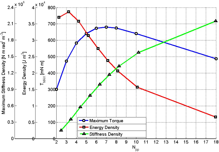
Maximum torque TMAX (circular markers), energy density (square markers) and maximum stiffness density (triangular markers) computed for d = 0 mm and θ = 90°/Npp, as a function of Npp. Dout1, Dout2, Din1, Din2 as in Table 1, h1 = h2 = 10mm.
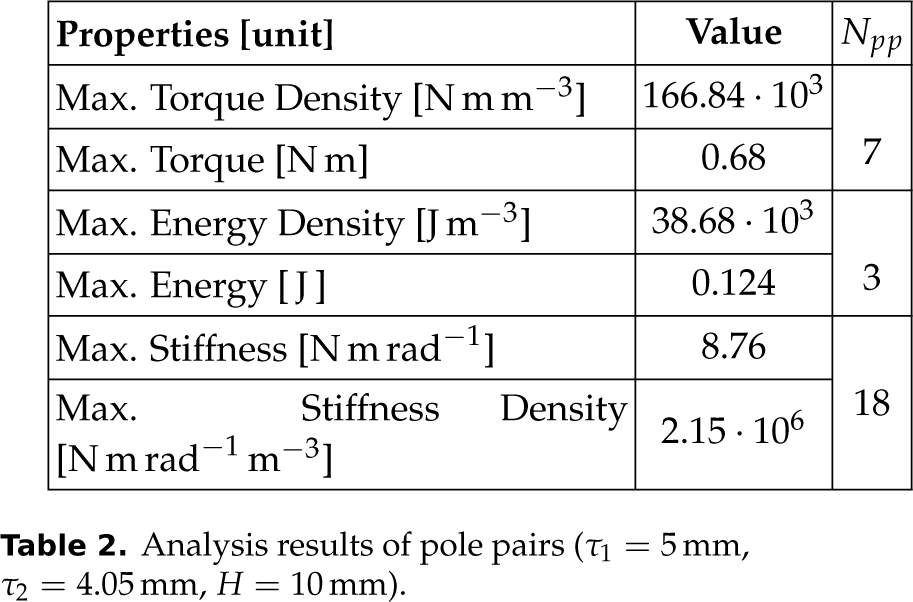
Analysis results of pole pairs (τ1 = 5mm, τ2 = 4.05mm, H = 10 mm).

4.1. Results
The first set of simulations (constant geometry, variable Npp) shows that maximum torque, stiffness and energy increase with Npp (Figure 13). In particular, for the geometry described in Section 4, the maximum torque density is 166.84 · 103 Nmm−3 for Npp = 7, the maximum energy density is 38.68 · 103 Jm−3 for Npp = 3 and the maximum stiffness density is 2.15 · 106 Nmrad−1 for Npp = 18 (Table 2).
The second set of simulations (variable geometry, Npp = 1) allowed us to identify the geometries that maximize torque, stiffness and energy per unit volume. It is to be noted that, in the case under consideration (Npp = 1), the latter two values numerically coincide for each geometry.
In detail, simulations returned a maximum energy density of 47.21 · 103 Jm−3 and a maximum torque density of 47.21 · 103 Nmm−3 for τ1 = 47.5mm, τ2 = 22.5mm, H = 32.5mm (Figure 15) and a maximum torque of 70.32Nm in correspondence to upper bounds (tau;1 = 50mm, τ2 = 52.5mm, H = 52.5mm), as summarized in Table 3.
5. Example applications
The scaling analysis reported above can be used to adapt the design of MAVERIC to specific needs. One example application is in the field of resonant motors for biorobotic applications [48]. In nature several animal species generate oscillatory movements by exploiting body stiffness, and this principle can be replicated in robots by properly coupling a motor to a compliant element acting as a spring. For example, the device presented in [48] uses a torsion spring with a stiffness of 1.6 · 10−3 Nmrad−1 and a stiffness density, calculated from the data reported in the paper of about 2.32 · 104 Nm rad−1 m−3. Both values can be rendered by MAVERIC, as shown in the previous section. Moreover, a variable stiffness compliant element would allow us to efficiently tune the oscillation frequency without compromising efficiency. As already mentioned, another important class of potential applications is represented by VIAs and SEAs. For example, let's set as design targets a minimum peak torque Tem ≅ = 60Nm, a stiffness of about 300Nmrad−1, a deflection angle θmax = 10° ÷ 15°, a maximum diameter of 120mm and a thickness of 20mm. Considering the state of the art, such a spring would fit compliant actuators with a nominal power in the range 300 – 600W [25–27]. For such a design, the number of pole pairs needed is approximately given by Npp = 90°/θmax. Let's set Npp = 7 (rounding to the closest lower integer of 90°/12.5°). A preliminary design can be obtained by considering the scaling analysis results related to the case Npp = 1. The torque is almost directly proportional to the number of pole pairs. For a given geometry, if T1 is the maximum torque when Npp = 1, then the actual torque is approximately given by NppT1. The geometry, which for Npp = 1 provides an expected torque not less than Tem/Npp, is characterized by the following geometric parameters: τ1 = 30mm, τ2 = 22.5mm, H = 22.5mm. In fact, a device with such dimensions expectedly provides a maximum torque of 8.75Nm > 8.57Nm= Tem/Npp. In order to comply with the design requirement on height, this geometry needs to be slightly adapted as follows: τ1 = 36mm, τ2 = 20mm, H = 20mm. Numerical simulations are necessary to refine the evaluation of the expected performance. Simulations retrieved a maximum torque (for θ = 90°/Npp) of TMAX =55.52Nm, a maximum stiffness of 388.64Nmrad−1 and a maximum stored energy of 7.93 J (Table 4), in line with the design targets. For this device, the distance between the magnets at which perfect compliance occurs is d0 = 33.3mm, as it can be retrieved by linearly interpolating the torques for θ = 90°/7 when d varies from 0mm to 42mm with a step of 2mm. Overall, the outer diameter of the spring is 115mm, while the thickness varies from 20mm to 55.3mm, depending on the value of d.

Maximum torque as a function of magnet dimensions. Height of magnet (H) varies from 2.5mm to 52.5mm by steps of 10mm. Maximum torque increases with dimensions. When tau;1 = 50mm, τ2 = 52.5mm, H = 52.5mm the maximum torque is 70.32 Nm.
Calculated performance for Npp = 7, τ1 = 36mm, tau;2 = 20mm, H = 20mm.


Torque density for different geometries. Maximum torque density is 23.82Nmm−3 for τ1 = 47.5mm, τ2 = 22.5mm and H = 32.5mm.
The two examples reported above show how the MAVERIC principle can be applied in robotics. The potential drawback represented by dimensions and weight in certain applications may be counterbalanced by a number of positive aspects. First of all MAVERIC is not affected by overloading issues, because an excessive torque would cause pole slipping, thus preventing mechanical failures, which may conversely occur in metal springs [27]. Moreover, MAVERIC intrinsically has an infinite fatigue life. While the two above-mentioned advantages are characteristic of magnetic couplers, MAVERIC is characterized by a third feature, consisting of its capability to continuously vary the intrinsic stiffness from a maximum value down to the perfect compliance condition. Once set, stiffness can be kept constant without supplying current, e.g., by using a non-backdriveable mechanism to adjust d, with energetic advantages over existing solutions (e.g., [20]). Variable intrinsic stiffness is important, for example, to efficiently modulate the frequency of resonant motors, to tune the stiffness of compliant actuators or to separate the load from the actuator without resorting to control-based strategies or additional mechanical components (e.g., clutches).
6. Conclusions and future work
In this paper we reported on a novel concept of a magnetic variable stiffness coupler that can also be used as a clutch. Both simulations and experimental measurements have been performed to prove the effectiveness of the proposed concept. The proposed device offers a good trade-off between compactness, reliability, variable compliance and backdrivability. Scaling analysis indicates a maximum torque density of 166.84 · 103 Nmm−3. Simulations show that a large range of stiffness, maximum stored energy and torque can be obtained by changing dimensions and the number of pole pairs. Therefore, the actual embodiment of the MAVERIC principle can be chosen in order to meet the requirements of specific applications. To this end, a semi-analytical model, inspired by [47], will be implemented in order to obtain a computationally efficient tool for optimizing MAVERIC for specific applications. Furthermore, a VSA incorporating a MAVERIC is under development for the actuation of the spine of a robotic fish [49].