
Abstract
When the quadruped robot is in locomotion such as jumping and running with higher speed, there is non-continuous contact force between the foot and the environment inevitably. In order to achieve the flexible force interaction of the bionic legs with the environment, it is necessary to analyze the joint angular stiffness of the bionic leg. In this article, based on the designing principles of the bionics, light-weighted, and flexible, a kind of musculoskeletal bionic leg mechanism driven by pneumatic artificial muscles is presented by inspiring from the biological cheetah anatomy and physiology muscle distribution. The kinematics of the bionic leg is analyzed to obtain the Jacobian matrix. In order to achieve high-speed jumping and soft landing of the bionic leg, a kind of foot stiffness model is presented by analyzing the foot elastic potential energy caused by the contact force. The mapping relationship between the joint stiffness matrix and the foot stiffness matrix is obtained by the Jacobian matrix. Then, the dynamics of the bionic leg is analyzed to determine the relationship between the joint angular stiffness and the pneumatic artificial muscle gas pressure. Finally, the experiment on controlling the pneumatic artificial muscles gas pressure for tracking the joint angular stiffness of the bionic leg is conducted. By regulating the pneumatic artificial muscle gas pressure, the needed pneumatic artificial muscle gas pressure that could meet the desired foot stiffness ellipse model can be determined. The study will pay a theoretical foundation for controlling the pneumatic artificial muscles to achieve the high-speed locomotion of the bionic leg.
Keywords
Introduction
Bionic robot is the combined product of bionics and robotics technology, and it is an important research direction in the field of robotics. Bionic robots should be developed by inspiring from the biological principles, such as the biological structure, function and motion principles. Thus the bionic robots could have the biological locomotion ability. Based on studying the biological analysis of various physiological structures, movement style, and so on, various bionic robots have developed worldwide. 1 On the other hand, the bionic robot can be used as a scientific model to explore the biological behavior patterns adapting to the natural environment. The bionic robot can provide physical model to study the biological mechanisms, biological structures, biomechanics, and musculoskeletal systems. 2
As pneumatic artificial muscles (PAMs) have many desirable characteristics, such as flexibility similar to biological muscles, high power to weight ratio, high power to volume ratio, and inherent compliance, they have therefore been widely used in various robotic systems. 3 In 2010, Hosoda et al. 4 designed a jumping robot driven by PAMs to duplicate human leg structure and function. The role of the biarticular muscles and the monoarticular muscle was investigated. The jumping experiment was conducted to evaluate the role of each muscle. Niiyama et al.5,6 developed a musculoskeletal bipedal running robot driven by PAMs, which is named as Athlete robot. Based on the bionics principle, the bionic design ideas of the elastic tendons, monoarticular muscle, and antagonistic driving method were adopted. The arrangement of the PAMs is inspired from the muscle of the human lower leg. Based on the biomechanical principles of the elastic tissue, the lower leg was designed with an elastic blade foot, so the locomotion performance of the legged robot was improved. The PAMs activation patterns are determined using a model of the musculoskeletal leg based on the measurement of muscle activation and kinetic data of the human running movements. The motion capture system and force measurement platforms were adopted to measure the running speed and the ground reaction force. The running simulation and experiment were performed, and the robot can achieve eight gait cycles running with velocity of 3 m/s.
In the study of the quadruped robots driven by PAMs, several robots have been developed worldwide. Yamada and colleagues7,8 developed a quadruped musculoskeletal robot named PIGORASS, which is inspired from the muscles arrangement of the biological creature, as shown in Figure 1(a). The acrylonitrile butadiene styrene (ABS) resin and carbon fiber–reinforced composite materials were used to reduce the weight. The biological principle of the body and nervous system working together to generate coordinated locomotion pattern was analyzed, and the dynamic jumping experiment was performed. The quadruped robot can achieve the jumping locomotion similar to the rabbit. In 2012, Li et al.9–11 developed a quadruped bionic robot, which is driven by PAMs, as shown in Figure 1(b). The characteristics of the biological muscle and the PAM were studied, and the bionic joint model was established. The experiment was conducted to improve the flexibility and stability of the robot.

Musculoskeletal bionic robot: (a) quadruped musculoskeletal robot, (b) bionic cheetah robot, and (c) quadruped bionic walking robot.
In 2012, Miki and Tsujita12,13 presented a kind of musculoskeletal quadruped robot, as shown in Figure 1(c). He proposed that the dynamic stability of the quadruped robot strongly depends on the mechanical properties of the body mechanism. Then, the changeable stiffness property of the bionic body was studied by the experiments. When the quadruped robot walks with the crawl gait, trot gait or pace gait respectively, the effect of the body stiffness on the walking stability and the locomotion energy were analyzed.
For the quadruped robot driven by PAMs, the reasonable planning of the joint stiffness of the bionic leg is the key to achieve the dynamic jumping and soft landing. In order to reduce the contact force and to improve the locomotion speed and mobility of the quadruped robot, it is necessary to plan and control the joint stiffness. 14
There have been many studies so far about the joint stiffness control of the musculoskeletal robot. Tsujita et al. 15 presented a kind of biped robot driven by PAMs. The effect of the joint stiffness on the walking stability was analyzed. The relationship between the muscle tension and the movement performance of the robot was studied. Considering the foot contact force feedback, an oscillating controller was designed to control the joint motion, and the joint stiffness was outputted. The simulation and experimental results show that the appropriate joint stiffness could keep the stable locomotion of the robot. Nakamura et al. 16 pointed out that the conventional stiffness control by torque-based methods depends on the position control response. Therefore, the position and stiffness control need to be independent of each other. The new method based on the mechanical equilibrium model was presented for joint stiffness control. For the antagonizing bionic joint with 1 degree of freedom (DOF), the joint position and stiffness decoupling control experiments were conducted under the condition of the transient impact loads. In the experiment, the desirable joint stiffness is applied at a constant value. Wang et al. 10 developed a quadruped robot driven by PAMs. The basic position control method and model-based position control method were adopted, the position control experiments on the bionic joint were performed, and the joint angular stiffness changes with time were outputted according to the joint position control results. Kang 17 studied the force control of the antagonistic bionic joint driven by PAMs. The variable stiffness capability of PAM was investigated. The sliding mode control scheme was adopted to control the contacting force between a linkage actuated by PAMs and a rigid environment, and the experimental results show that the control algorithm could achieve better force tracking performance. The joint stiffness had not been studied yet. Xie et al. 18 presented a bionic leg mechanism driven by PAMs. The driving torqued of the joint is derived based on the PAM force model, and the proportional–integral–derivative (PID) control algorithm was adopted to control the joint driving torque. The mechanical and control co-simulation was performed by the virtual prototyping technology to evaluate the effectiveness of the control algorithm. T Kaneko et al. 19 presented a kind of biped robot. The characteristic of the dynamic locomotion, such as jumping or running was studied. The control method was analyzed to reduce the impact force between the robot and the environment. The stiffness ellipse concept was proposed. As the relationship between the ground reaction force and the stiffness ellipse is almost linear, the ground reaction force can be effectively controlled by adjusting the stiffness ellipse. The ground reaction force of the foot was controlled to achieve stability dynamic movement.
When the quadruped robot is in locomotion with higher speed, there is instant impact force between the foot and the environment. How to reduce effectively the impact force is the key for the robot. In order to reduce the non-continuous contact impact between the foot and the environment, there is a need to control the joint stiffness to ensure that the leg has action consistency and flexibility during the condition of the different locomotion speeds or ground contact stiffnesses. The joint stiffness should change with foot contact stiffness or load and has better variable characteristics. Thus, the robot could achieve better locomotion performance with higher speed. To improve the locomotion performance of the quadruped robot, it is necessary to plan and control the joint stiffness of the bionic leg to achieve dynamic jumping and soft landing.
Thus, it is necessary to perform the joint variable stiffness planning of the leg of the quadruped robot. The bionic leg of the quadruped robot should have suitable joint stiffness to adapt to different locomotion speed, and to achieve jumping and soft landing. The reasonable joint stiffness planning of the quadruped robot bionic leg is the key to achieve high-speed dynamic locomotion performance.
Based on the design principles of the bionic, lightweight, and flexible, with reference to the anatomy of the cheetah legs, the 3-DOF bionic leg mechanism driven by the PAMs is presented, the DOF and PAMs of the bionic leg are reasonably arranged, and the mechanical structure is optimized to obtain enough larger rotating range of the joint. In order to improve the flexibility of the bionic leg jumping with higher speed, a kind of foot ellipse stiffness model is presented by analyzing the elastic energy from the foot contact deformation. The foot ellipse stiffness is mapped by the Jacobian matrix of the bionic leg, and the joint angular stiffness of the bionic leg is obtained. According to the joint force balance of the bionic leg, the dynamics and the joint angular stiffness are analyzed. Based on the Chou force model of the PAM, the theoretical relationship between the joint angular stiffness of the bionic leg and the PAM inner gas pressure is determined. Thus, the relationship between the PAM inner gas pressure and the foot desired stiffness model is derived. Finally, the experiment is conducted to tracking the joint stiffness of the bionic leg by regulating the PAM pressure, and then the desired joint angular stiffness can be obtained to meet the foot stiffness planning. Studying on the PAMs pressure controlling to obtain reasonable joint angular stiffness will lay foundation for achieving dynamic jumping locomotion of the quadruped robot.
Musculoskeletal bionic leg
Anatomical structure of cheetah hind limb
The cheetah is one of the four-legged creatures with the highest speed on land. The cheetah is generally regarded as a study object for developing the bionic robot because of its excellent running and jumping locomotion ability. When the cheetah is running at a higher speed, over 50% of the energy is provided by the muscle contraction. Regarding the musculoskeletal anatomy structure and movement principles of the quadruped creatures, biologists have studied the cheetah and other four-legged creature. 20 The anatomy structure and distribution skeletal muscle of the cheetah hind limb are shown in Figure 2.

Main muscles of cheetah hind limb.
The hind limbs of the cheetah play an important role during the cheetah dynamic movements, such as running and jumping locomotion. The motion range of each joint of cheetah hind limb is different. The hip joint, knee joint, and the ankle joint can reach 145°, 104°, and 95°, respectively. The motion range of the hip joint is maximum, which is followed by the knee and it is minimum in the ankle.21,22
There are many muscles in the cheetah hind limb. The coordinated movement of these muscles plays an important role for the cheetah locomotion.
Musculoskeletal bionic leg
The unique biological structure and movement principles are the result of long-term biological evolution adapting to the natural environment. The innovative design of the musculoskeletal bionic leg in this article is inspired from the four-legged biological muscles arrangement and coordination driving principles by multi-muscles, which could provide a sufficient large motion range and jumping force of the bionic leg. Based on the principle, the biological structure, biological motion, biological muscles arrangement, the elastic tendons, and the bionic design ideas of the monoarticular muscles and antagonistic muscles are adopted. Because the muscles supply force only in the contraction direction, they are arranged antagonistically to supply both positive and negative torque at the joint. The bionic leg presented in this study imitates the cheetah muscle arrangement. Each joint is driven by PAM from FESTO company, which is similar to the characteristics of creature muscle and has an extremely high power/weight ratio.
The mechanical structure of the bionic leg directly affects the locomotion performance of the quadruped robot with higher speed. Based on the design principles of the bionic, lightweight, and flexible, the bionic leg mechanism driven by PAMs is presented for quadruped robot. The structural parameters of the bionic leg mechanism are optimized in order to achieve relative larger rotating range of the joint and meet the need of the jumping movement. From the points of the bionic mechanism, bionic material and bionic driving, the PAMs similar to the biological characteristics of muscle are adopted. The musculoskeletal leg is developed to achieve the coordinated movement. Thus, the joint could have the characteristic of variable stiffness to meet the need of jumping and soft landing. The lightweight carbon fiber or aluminum alloy material is adopted as the skeleton of the bionic leg. Two PAMs are adopted to drive a joint in order to obtain a sufficiently large rotation range.
Based on the design principles of the structure compact, good bionic, and so on, a 3-DOF bionic leg driven by five monoarticular PAMs is designed by referencing the hindlimb muscles arrangement, DOF distribution and hindlimb length of the cheetah. From top to bottom, the joints such as side-swing hip joint, forward-swing hip joint, knee joint, and passive ankle joint are shown in Figure 3.
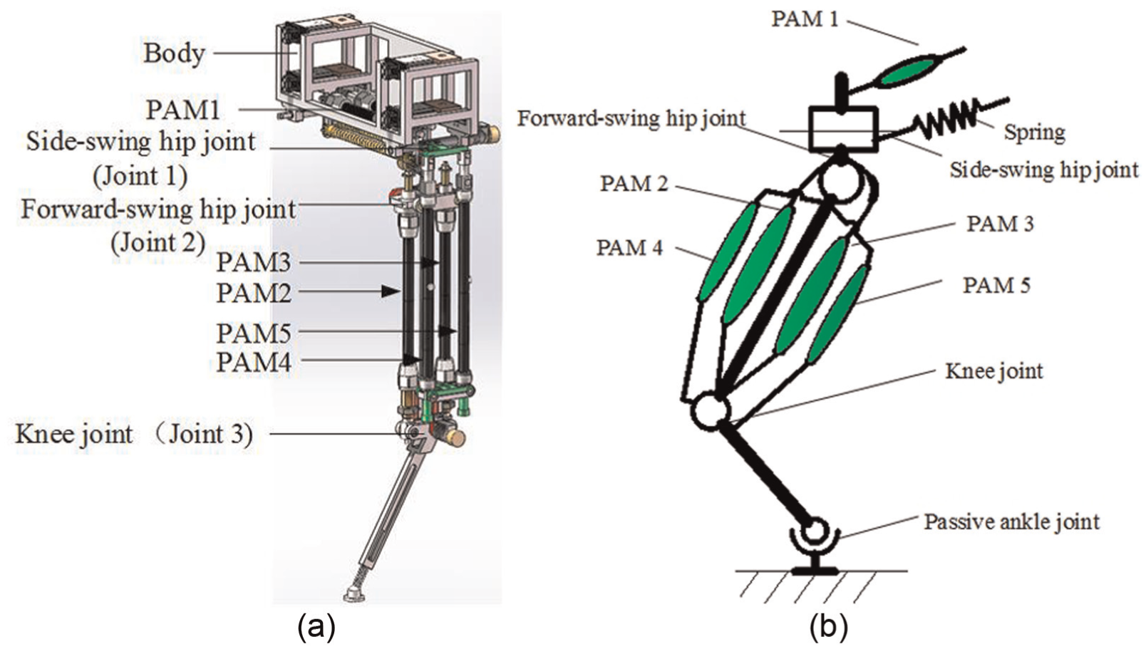
Musculoskeletal leg and the PAM arrangement: (a) bionic leg model and (b) PAM arrangement of bionic leg.
As the PAM can only provide the contraction force, PAM is generally arranged in pairs to reduce the antagonistic for the flexion and extension of the joint. The forward-swing hip joint and knee joint are designed as antagonistic bionic joint driven by two monoarticular PAMs, respectively. As the side-swing hip joint is mainly used to achieve the spinning gait or turning gait, which is not higher speed locomotion style, the side-swing hip joint is designed with one PAM and a spring, and this PAM is arranged along horizontal direction. The PAMs of the forward-swing hip joint and the knee joint are located in different planes, which is to obtain enough length of PAM to ensure the joint larger movement range. The rotating ranges of the side-swing hip joint, the forward-swing hip joint, and the knee joint are 23°, 60°, and 55°, respectively.
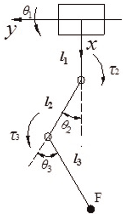
Jacobian matrix
The jumping kinematics of the bionic leg is to determine the relationship between the foot displacement and the joint angular displacement. The velocity Jacobian matrix can be determined by the kinematics. The kinematic analysis diagram of the bionic leg is shown in Figure 4.
Kinematic of bionic leg.
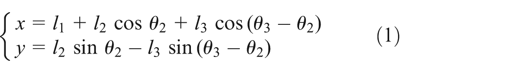
The foot displacement of the bionic leg is as follows
where
Then, the velocity Jacobian matrix of the leg is as follows


PAM force model
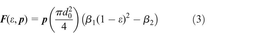
PAM force model has been studied by many researchers, which describes the relationship between PAM output force, inner gas pressure, and contraction ratio. For different types of the PAM, there are different expressions.23,24 According to the Chou model, the relationship between PAM force, inner pressure, and contraction ratio can be expressed as follows
where
Joint driving torque and angular stiffness
For the 3-DOF musculoskeletal bionic leg, the dynamics need to be analyzed only considering the forward-swing hip joint and the knee joint. The joint driving torque can be determined. Then, the joint angular stiffness can be derived by the joint torque, and the relationship between the joint angular stiffness and the PAM gas pressure can be obtained.
The inertial force caused by the acceleration is not considered. From Figure 5, the driving torque of the forward-swing hip joint and the knee joint are as follows

where

Joint force analysis: (a) forward-swing hip joint and (b) knee joint.
Then, the joint angular stiffness can be calculated as follows

where
Foot stiffness planning
There is a mapping relationship between the joint stiffness and the foot stiffness of the bionic leg. The desired foot stiffness model can be set for the bionic leg with higher speed locomotion. Then, the desired joint stiffness can be derived from the foot stiffness model by the Jacobian matrix.
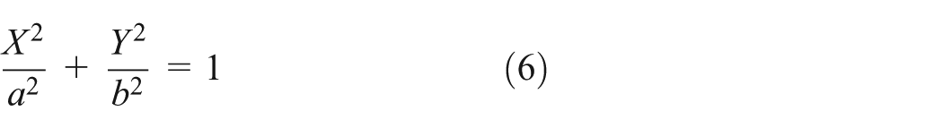
First of all, the foot stiffness needs to be planned. The foot elastic potential energy caused by the contact deformation is planned as an ellipse. The coordinates of any point on the stiffness ellipse indicate the deformation.
As an ellipse equation is equal to 1, that is, the elastic potential energy of foot expressed by an ellipse is an equal potential energy, and the value of the potential energy is 1. This equal potential energy line can be used to plan the foot stiffness.
A kind of ellipse stiffness model is presented as the desired foot stiffness, which can be only determined by three parameters: the length of the major axis length, the length of the minor axis, and rotation angle. The joint angular stiffness of the bionic leg can be derived by the foot ellipse stiffness model.
The stiffness ellipse represents the foot stiffness distribution in a two-dimensional (2D) plane. Three parameters express uniquely a stiffness ellipse, which are the major axis length 2a, the minor axis length 2b, and the rotating angle

Foot stiffness ellipse.
The foot elastic potential energy caused by the foot contact impact force is expressed by the ellipse shown in Figure 6. The ellipse equation is as follows

Then the ellipse can be expressed as follows
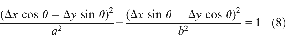
The equation (8) is simplified as follows

In the foot coordinate system, the foot elastic potential energy can be expressed as follows
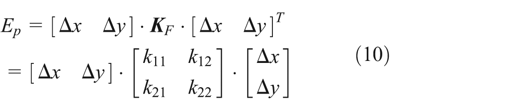
where
Let

Thus, the ellipse that expresses the foot elastic potential energy can reflect the foot stiffness changing. The distance from the ellipse central point to the point on the ellipse is set as
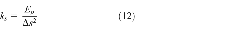
Then

Thus, the relationship between the equal elastic potential line and the foot stiffness ellipse is determined. A stiffness ellipse has three parameters: minor-axis a (N/m), major-axis b (N/m), and the angle of the stiffness ellipse θ (rad). These three parameters can be arbitrarily set. By determining these three parameters, the joint angular stiffness can be calculated.
Desired joint angular stiffness
As the forward-swing hip joint and the knee joint are related to the jumping movement of the quadruped robot, so the joint stiffness is only analyzed for the two joints. As the Jacobian matrix expresses the relationship between the foot force and the joint torque, the relationship between the joint angular stiffness and the foot stiffness of the bionic leg can be mapped by the Jacobian matrix. According to planned foot ellipse stiffness model and the foot stiffness matrix, we can establish the relationship between the foot stiffness matrix and joint stiffness matrix by the Jacobian matrix, and then the desired joint angular stiffness can be determined.
Joint stiffness matrix
As the PAMs used in the bionic leg are all the monoarticular muscle, the joint stiffness matrix can be expressed as follows

where
The side-swing hip joint of the bionic leg is not considered; for 2-DOF bionic leg mechanism, the relationship between the increment of the joint driving torque and the joint angular displacement is as follows

where
The relationship between the ground reaction force and the joint driving torque can be expressed by the force Jacobian matrix
where
According to equations (15) and (16)

where
where
Then the relationship between the ground reaction force and the deformation can be expressed as follows

Let
The relationship between the joint stiffness matrix and the foot stiffness matrix can be calculated by the Jacobian matrix

Then, the joint stiffness matrix can be derived by equations (2) and (21) as follows

where

Desired joint angular stiffness
According to equation (22), the desired joint angular stiffness can be obtained by the foot stiffness ellipse model

Parameters of the bionic leg.

PAM: pneumatic artificial muscle.
The shape and the orientation of the foot stiffness ellipse change with three parameters a, b, and
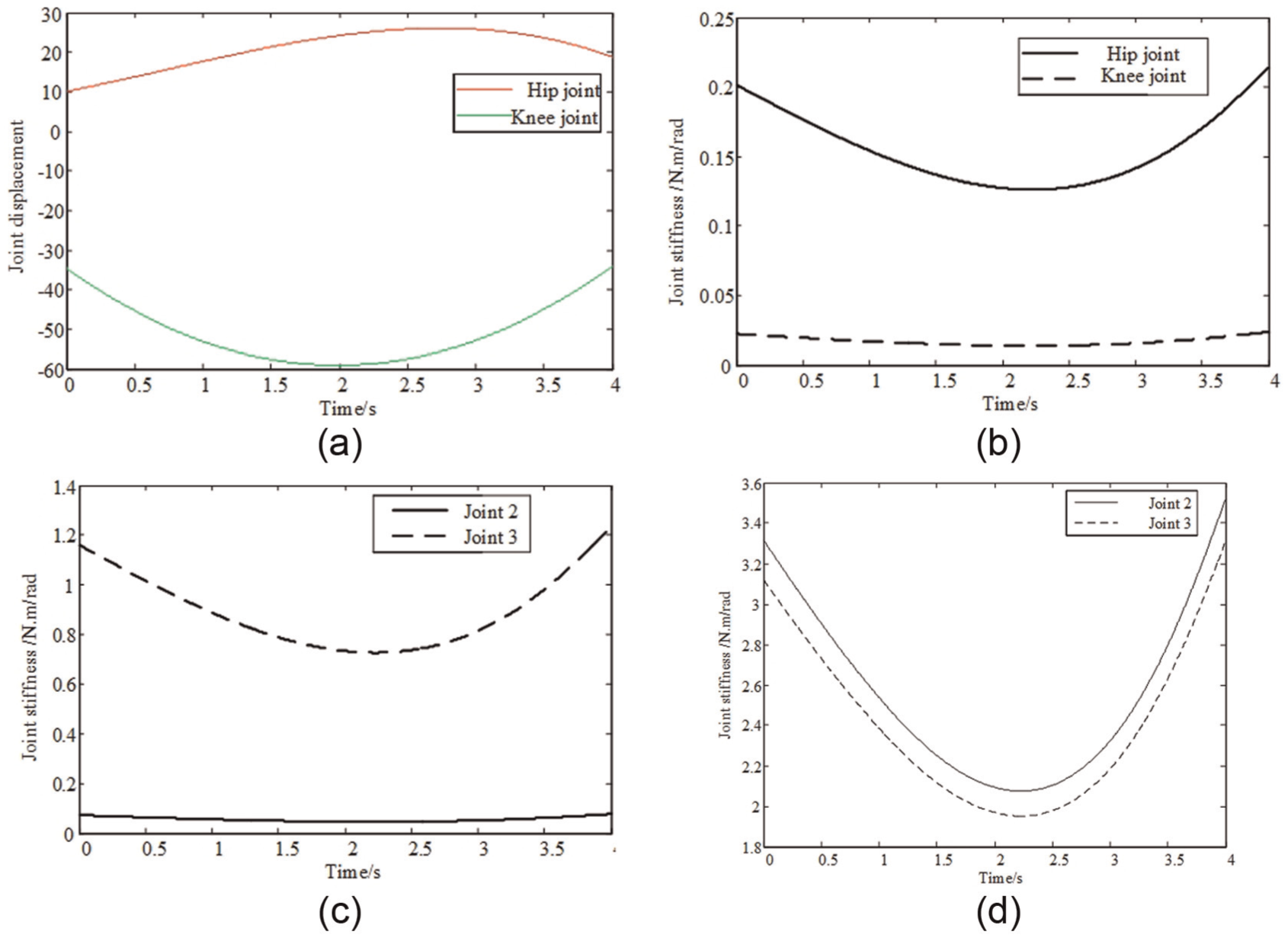
Joint angular displacement and joint angular stiffness: (a) joint angular displacement, (b) joint angular stiffness
The calculating results of the joint angular displacement are shown in Figure 7(a), and the calculating results of the joint angular stiffness by the foot stiffness planning are shown in Figure 7(b)–(d). The joint angular stiffness changes with different parameters of the foot stiffness ellipse.
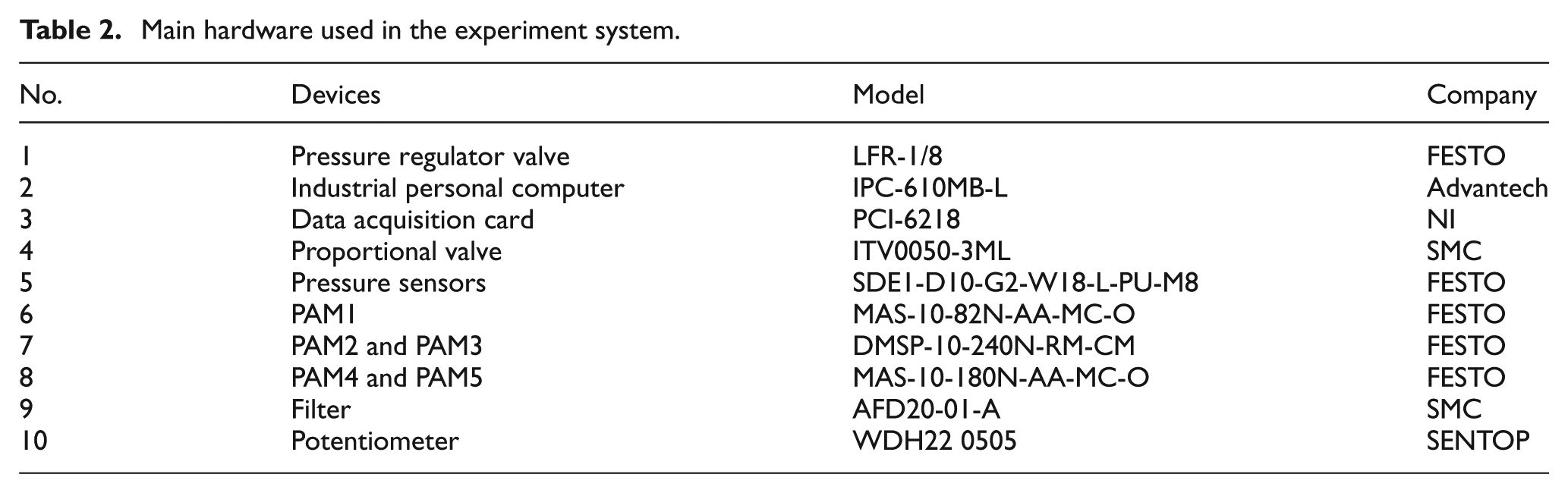
Main hardware used in the experiment system.
Experiment
The experiment is conducted to obtain the characteristic of the joint angular stiffness and gas pressure. For the musculoskeletal leg proposed in this article, the relationship between the actual joint stiffness and the PAM gas pressure changing with time can be measured. The experimental system of the musculoskeletal leg is shown in Figure 8. The control experiment on the joint angular stiffness is performed to analyze the tracking effects of the joint angular stiffness, and the joint angular stiffness pressure characteristics.
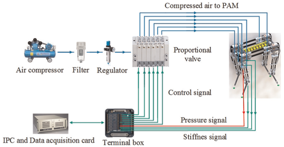
Experimental system.
The PID algorithm is adopted to study the joint angular stiffness tracking experiment. The desired joint angular stiffness is shown in Figure 7(d). The tracking results of the angular stiffness of the forward-swing joint and knee joint are presented.
The PAM axial output force is provided when contraction produces, so two PAMs are used in the forward-swing hip joint or the knee joint, which is called as the antagonistic bionic joint. The joint angular stiffness is determined by the internal gas pressure of two PAMs. The joint angular stiffness is tracked by controlling the PAMs gas pressure to meet the foot stiffness planning.
For the experiment, the initial gas pressure is 0. Gas pressure of corresponding PAMs is adjusted to appropriate value for tracking the joint angular stiffness. The tracking results of forward-swing hip joint are shown in Figure 9. The PID parameters are

Joint angular stiffness tracking results of joint 2: (a) comparison of desired value and experimental value of joint angular stiffness and (b) PAM gas pressure.
The tracking results of knee joint are shown in Figure 10. The PID parameters are

Joint angular stiffness tracking results of joint 3: (a) comparison of desired value and experimental value of joint angular stiffness and (b) PAM gas pressure.
The joint driving torque can be calculated by the Chou force model, as shown in Figure 11.

Joint driving torque.
Conclusion
In order to achieve the jumping or running locomotion and stable landing of quadruped robot, the joint angular stiffness of bionic leg needs to be planned and controlled. This study aims to determine the desired joint angular stiffness by the foot stiffness planning.
First, a musculoskeletal leg mechanism driven by PAMs for quadruped robot is presented. The kinematics modeling is analyzed, and the velocity Jacobian matrix is obtained. Based on the Chou force model of the PAM, the joint driving torque and the joint angular stiffness are derived by the joint force balance. Thus, the relationships between the joint angular stiffness of the bionic leg and the PAM gas pressure can be determined. Second, the relationship between the joint stiffness matrix and the foot stiffness matrix of the bionic leg can be mapped by the velocity Jacobian matrix. Based on foot elastic potential energy of the bionic leg, the foot stiffness elliptical model proposed can be mapped to the joint by the Jacobin matrix to obtain the desired angle joint stiffness. Finally, the experimental study on the joint variable stiffness control of the bionic leg is performed. The PAM gas pressure is regulated to track the desired joint angular stiffness; thus, the PAM gas pressure can be determined to meet the foot stiffness elliptical model. Experimental results show that the desired joint angular stiffness could be controlled by the foot stiffness model, and the better tracking effectiveness has been obtained.
The study in this article, the relationship between PAM pressure and foot stiffness model can be obtained by analyzing the joint driving torque, joint angular stiffness. Controlling the PAM pressure is to achieve the joint variable stiffness characteristics, which is benefit to achieve the leg locomotion with higher speed and soft landing. In the future, the decoupling method of the joint position and stiffness of the bionic leg will be studied.
Footnotes
Academic Editor: José Tenreiro Machado
Declaration of conflicting interests
The author(s) declared no potential conflicts of interest with respect to the research, authorship, and/or publication of this article.
Funding
The author(s) disclosed receipt of the following financial support for the research, authorship, and/or publication of this article: This study was supported by the National Natural Science Foundation of China (grant no. 51375289) and Natural Science Foundation of Shanghai (grant no. 13ZR1415500).