
Abstract
It is significant for the final goal of RoboCup to realize the recognition of generic balls for soccer robots. In this paper, a novel generic ball recognition algorithm based on omnidirectional vision is proposed by combining the modified Haar-like features and AdaBoost learning algorithm. The algorithm is divided into offline training and online recognition. During the phase of offline training, numerous sub-images are acquired from various panoramic images, including generic balls, and then the modified Haar-like features are extracted from them and used as the input of the AdaBoost learning algorithm to obtain a classifier. During the phase of online recognition, and according to the imaging characteristics of our omnidirectional vision system, rectangular windows are defined to search for the generic ball along the rotary and radial directions in the panoramic image, and the learned classifier is used to judge whether a ball is included in the window. After the ball has been recognized globally, ball tracking is realized by integrating a ball velocity estimation algorithm to reduce the computational cost. The experimental results show that good performance can be achieved using our algorithm, and that the generic ball can be recognized and tracked effectively.
1. Introduction
The ball is the chasing focus for soccer robots in the RoboCup Middle Size League (MSL) competition, so ball recognition is a research focus for MSL teams. Currently, almost all of the robots can recognize the colour-coded balls, like the orange or yellow ball, effectively. To foster research into robot vision and realize the final goal of RoboCup such that a team of fully autonomous humanoid robots could win against the human world soccer champion team by 2050, the colour-coded extent of the RoboCup MSL environment should be gradually reduced. One of the most important changes might be that the colour-coded ball will be replaced with a generic ball in the competition. So, soccer robots should be able to recognize the generic FIFA balls with arbitrary colours or textures like human beings. This has become a challenging issue in the research into robot vision for RoboCup MSL soccer robots, because the traditional ball recognition methods based on colour classification [1, 2] cannot be used any more.
In this paper, the AdaBoost learning algorithm - which has been both popular and successful in the pattern recognition community - is applied to solve this problem based on omnidirectional vision by combining the modified Haar-like features. As such, a novel generic ball recognition algorithm is proposed for our NuBot soccer robots. The following sections are organized as follows: the related research is introduced in Section 2; our omnidirectional vision system is introduced briefly in Section 3; our recognition algorithm is proposed in Section 4; thorough experiments are performed in Section 5 to validate the effectiveness of our algorithm; conclusions and future work are presented in Section 6.
2. Related research
A so-called ‘contracting curve density’ (CCD) algorithm [3–5] was proposed by Hanek et al. to recognize soccer balls without colour labelling. This algorithm fits parametric curve models with image data by using local criteria based on local image statistics to separate adjacent regions. The contour of the ball can be extracted even in cluttered environments under differing illumination, but the vague position of the ball needs to be known in advance. Therefore, global detection cannot be realized using this method. Treptow and Zell integrated the Adaboost feature learning algorithm into a condensation tracking framework [6] so that a ball without a special colour could be detected and tracked in real-time, even in cluttered environments. Mitri et al. presented a novel scheme [7] for fast colour invariant ball detection, in which the edged-filtered images serve as the input of an Adaboost learning procedure that constructs a cascade of classification and regression trees. Different soccer balls could be detected by this method in different environments, but the false positive rate was high when there were other round objects in the environment. As such, they combined a biologically-inspired attention system-VOCUS [8] with a cascade of classifiers. This combination made their ball recognition highly robust and eliminated false detection effectively. However, the computational load was quite high, especially in detecting regions of interest in VOCUS, even when the dimension of the image was only 320*240. Thus, the real-time requirement could not be met. Coath and Musumeci proposed an edge-based arc-fitting algorithm [9] to detect the ball for soccer robots. Bonarini et al. used a circular Hough transform on the edges extracted from a colour invariant transformation algorithm to detect the generic ball, and a Kalman Filter was also applied to track and predict the position of the ball in the next image to reduce the computational load [10]. An advanced version of the Hough transform was proposed to detect the ball without colour information by using the structure tensor technique in [11], but this method is time consuming and it cannot be run in real-time.
However, the algorithms mentioned above were only used in the perspective camera in which the field of view was far smaller and the image was also much less complex than that of an omnidirectional vision system. An omnidirectional vision system can provide a 360° view of the robot's surrounding environment in a single image, and they can use it to realize object recognition in the larger scale in comparison with a perspective camera with a limited field of view. So, it is more significant to realize the recognition of generic balls based on an omnidirectional vision in improving robots' ability as regards visual perception. However, the characteristic of a wider field of view also leads to the lower imaging resolution of the panoramic image, and the imaging of the ball itself is usually small on the image, which brings about a difficulty with ball recognition based on omnidirectional vision. Recently, some researchers have used omnidirectional vision systems to recognize arbitrary FIFA balls [12–14]. Because their panoramic mirrors are hyperbolic, the balls are imaged as circles in the panoramic images. Thus, Martins et al. used a canny operator to detect the edges, and then applied the circular Hough transform to detect all the candidate circles imaged by the balls [12, 13]. An effective validation process was proposed to discard the false positives. Zweigle et al. used a standard Hough transform to detect all the circles in the panoramic image and then extracted a colour histogram for each circle and compared it with a colour histogram learned in the offline calibration process to validate the real FIFA balls [14]. The offline calibration step was needed in this method. Experimental results showed that the correct detection rates were very high when using these two methods. However, the experiments were performed in very clean environments, and these two methods have not been tested fully in dynamic and complex competition environments.
We have also proposed an arbitrary ball recognition algorithm based on our omnidirectional vision [15, 16]. The conclusion was derived such that the ball on the field could be approximately imaged as an ellipse in panoramic images, so the ball could be recognized without colour classification by detecting the ellipse with an image processing algorithm. Once the ball has been detected globally, the ball can be tracked in real-time by integrating a ball speed estimating algorithm. The experimental results show that the arbitrary FIFA ball can be recognized and tracked effectively in real-time. This algorithm does not need any learning or training steps, and global recognition can be dealt with by it; however, it is parameter-dependent and empirical, and several thresholds should be determined in image processing for detecting the ellipse imaged by the ball through numerous experiments. To deal with this problem, in this paper, we try to apply the AdaBoost learning algorithm to solve generic ball recognition based on omnidirectional vision by combining the modified Haar-like features. The conclusion derived in [15, 16] that the ball on the field could be approximately imaged as an ellipse in panoramic images is important for the recognition algorithm of this paper. To our knowledge, this is the first time that AdaBoost learning is used for object recognition with omnidirectional vision.
3. The omnidirectional vision system
Our RoboCup MSL soccer robot is equipped with an omnidirectional vision system developed by ourselves [17], as shown in Figure 1. The new panoramic mirror used in our omnidirectional vision system consists of a hyperboloidal mirror, a horizontally isometric mirror and a vertically isometric mirror from the interior to the exterior [15, 16]. So, the omnidirectional vision system not only makes the imaging resolution of the objects near the robot on the field constant and the imaging distortion of the objects far from the robot small in the vertical direction, but it also enables the robot to acquire a very clear imaging of the scene that is very close to it, such as the robot itself. The camera that we use is a FireWire colour digital camera, EC 650C, made by Prosilica, and the resolution of the acquired image is 659*493 pixels. Of course, because of the imaging characteristics of omnidirectional vision, the resolution of the panoramic image that we acquire and process is less than 493*493 pixels in region of interest (ROI) mode. The typical panoramic images acquired by our omnidirectional vision system are demonstrated in Figure 2.
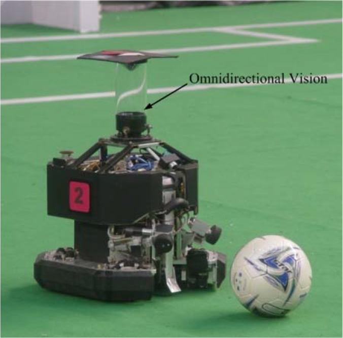
The NuBot soccer robot equipped with an omnidirectional vision system

The typical panoramic images acquired by our omnidirectional vision system
Our omnidirectional vision system is not a single viewpoint system; therefore, we use a model-free calibration method [18] proposed by Voigtländer et al. to calibrate it and to obtain the distance mapping from the image coordinate to the real world coordinate.
4. The proposed ball recognition algorithm based on omnidirectional vision
In this paper, Haar-like features [19, 20] and the AdaBoost learning algorithm [21, 22], which have been used successfully in many pattern recognition problems, are introduced to solve the generic ball recognition based on our omnidirectional vision. According to the imaging characteristics of our omnidirectional vision and the concrete requirement of ball recognition, the Haar-like features are modified. The proposed algorithm is divided into offline training and online recognition.
4.1 The offline training phase
In the offline training phase of our algorithm, the sub-windows including the ball (or not) are selected from the panoramic images to construct the training set of positive and negative images, and then the modified Haar-like features are extracted from the positive and negative images to construct the feature set. Finally, the training examples comprising the examples in the feature set and the corresponding labels (‘ball’ or ‘not-ball’) are used as the input to learn the classifier with the Gentle AdaBoost algorithm [22], which is an improved version of AdaBoost.
4.1.1 Constructing the example images
We acquire 26 panoramic images using our omnidirectional vision system, with some typical images shown in Figure 2. Each panoramic image includes about 10˜12 balls with different colours and textures, and the distances between the balls and the robot itself also vary.
The example images should be extracted from the acquired panoramic images. The sub-windows, including the ball (or not) can be selected manually through a human-machine interface. According to the imaging characteristics of our omnidirectional vision, the imaging of the ball is almost the same in the rotary direction of the panoramic image and the width of the rectangle including the just ball is about 20 pixels. However, the imaging of the ball varies greatly in the radial direction of the panoramic image, and the length of the rectangle just including the ball varies with the different distances of the ball to the robot itself. So, after selecting the sub-window rectangle with the width of 20 pixels including the ball, we rotate the sub-window to a fixed vertical direction, and then normalize it to become a new rectangle with a dimension of 20*20 pixels by zooming out the length of the sub-window rectangle to 20 pixels. The transformation process is demonstrated in Figure 3. During this process, the colour image is also transformed to become a grey image. The new rectangle with a fixed scale is used as the example image, and the modified Haar-like features can be extracted from it. All the rectangles containing a ball are used as the positive images. The rectangles without a ball but including all kinds of the typical background components, like the field, the robot, the white lines, etc., are extracted as negative images to improve the diversity of the example images.

Extracting the example image from the panoramic image by rotating and normalizing the sub-window
Figures 4(a) and (d) are the partial panoramic images and the green regions in Figures 4(b) and (e) are the sub-windows selected manually. Figures 4 (c) and (f) are the scaled-up positive and negative image, respectively, by rotating and normalizing the sub-windows. Finally, we obtain a positive set with 262 positive images and a negative set with 558 negative images. Some typical example images are shown in Figure 5.

(a) (d) The partial panoramic images. (b) (e) The sub-windows selected manually, shown as the green regions. (c) The scaled-up positive image. (f) The scaled-up negative image.
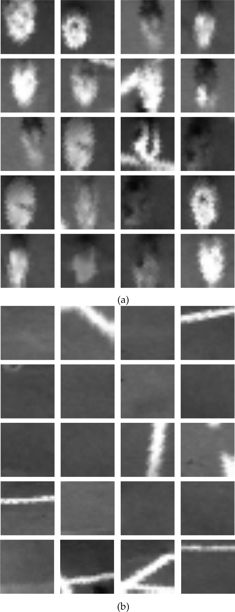
Some typical positive images (a) and negative images (b) from the positive and negative set for training
4.1.2 Extracting the modified Haar-like features
The Haar-like features were proposed and applied successfully in face detection by Viola and Jones [19]. A new image representation called the ‘integral image’ should be computed in advance, and then the Haar-like features can be calculated very quickly. To compute the value of the original Haar-like feature, the upright feature rectangle is divided into different combinations of the white sub-rectangle and the black sub-rectangle according to different feature types, as shown in Figure 6, and then the difference between the sum of the pixels within the white sub-rectangle and the black sub-rectangle area of the upright rectangle can be computed as the feature value. Lienhart and Maydt rotated the upright rectangle by 45° in the image, and then computed the feature value in the 45° rotated rectangle, so that the original set of the Haar-like features was extended by an efficient set of 45° rotated features [20].
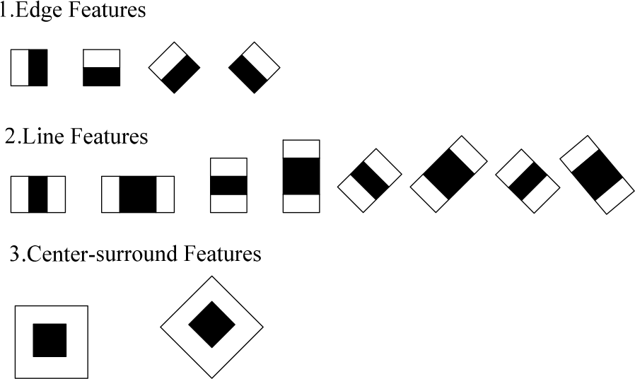
The feature rectangles used to compute the modified Haar-like features
In this paper, we also use the extended Haar-like features. Distinct from other application fields, like face recognition, the generic ball required to be recognized may have an arbitrary colour or texture, so the grey values of different balls can be very different after transforming the colour image into the grey image. When only using the difference between the sum of the pixels within the white sub-rectangle and the black sub-rectangle area of the feature rectangle as the feature value, the weak classifier is not robust enough for the balls with different colours, which results in that the number of the weak classifiers needed to construct the strong classifier increases. In the experiments, we also found that when we added another value as the feature value computed by using the division between the sum of the pixels within the white sub-rectangle and the black sub-rectangle part of the feature rectangle, the performance of the learned strong classifier could be enhanced for generic ball recognition, as shown in Section 5.1. So, the difference and the division between the sum of the pixels within the white sub-rectangle and the black sub-rectangle will be computed, respectively, as the values of our modified Haar-like features.
Three kinds of feature rectangles are used to compute the modified Haar-like features within each example image, which is the same as that in [20]. As shown in Figure 6, there are four edge feature rectangles, eight line feature rectangles and two centre-surround feature rectangles. After calculating the sum of the pixels within the white sub-rectangle and the black sub-rectangle for each feature rectangle, the subtraction and the division are performed between them to obtain two feature values. The dimension of the example image is 20*20 pixels. When setting the different dimensions of feature rectangles within the example image, the number of the modified Haar-like features extracted from an example image is shown in Table 1. In Table 1, b:w represents the ratio between the width of the black sub-rectangle and the width of the white sub-rectangle, and L and W represent the length and the width of the feature rectangle, respectively. Taking the upright feature rectangle as the example, when we calculate the edge feature, b:w is 1:1, L equals W, and we can set L and W as 2, 4, 6 and 8 pixels respectively. Furthermore, there are two kinds of upright edge features, namely horizontal and vertical, respectively (as shown in Figure 6), and the difference and the division between the sum of the pixels within the white sub-rectangle and the black sub-rectangle are computed as feature values respectively. So, the number of the upright edge features extracted from an example image is (19*19+17*17+15*15+13*13)*2*2=4176. From Table 1, 19,404 feature values can be computed from an example image, and then these values are concentrated to form a feature representing the example image. Because there are 262 positive images and 558 negative images, 820 features can be extracted. A part of these features and the corresponding labels (1 for ball, −1 for non-ball) will be used as the input of the AdaBoost learning algorithm to learn a classifier for ball recognition, and the rest of them will be used for testing after training.
The number of modified Haar-like features extracted from an example image

4.1.3 Learning the classifier for ball recognition
The AdaBoost learning algorithm is one of the most popular and successful algorithms to learn a classifier in the pattern recognition community [21]. It is based on the statistical learning theory, and its main idea is to obtain a strong classifier by integrating multiple weak classifiers so that the classification performance can be boosted. In this paper, we use an improved version of AdaBoost called the ‘gentle’ AdaBoost algorithm. After training with those features extracted in Section 4.1.2 and the corresponding labels as the input, a predefined number of the Haar-like features is selected, and the related weights and thresholds are also determined. As such, a classifier for generic ball recognition is learned. The detailed introduction about the gentle AdaBoost algorithm can be found in [22].
4.2 The online recognition phase
In the online recognition phase, the learned classifier is used to search and recognize the ball in the panoramic image acquired online by the robot. Firstly, the searching sub-window should be determined to judge whether there is a ball within it. According to the imaging characteristics of our omnidirectional vision system, the imaging of the ball varies along the radial direction of the panoramic image, and is almost the same along the rotary direction. So, the length of the searching sub-window should also vary along the radial direction of the panoramic image to guarantee that the whole ball can be included in the searching sub-window.
We assume that the ball is located on the ground field. The panoramic mirror can be considered as a point with height h above the ground field, since the mirror size is far smaller when compared to the ball size and the distance from the mirror to the ball. Therefore, the incident rays from the ball to the mirror can be said to form a cone tangent to the ball approximately. The sketch of the imaging of the ball is shown in Figure 7. We define a right-hand Cartesian coordinate with the centre of the robot on the plane as the origin O of the coordinate, and with the direction from the robot to the ball on the plane as the x axis. The radius of the ball is r and the distance between the ball and the robot itself in the robot-centred real world coordinate is xb. According to the characteristics of omnidirectional vision, the x axis will be imaged as the radial direction from the robot to the ball in the panoramic image.

A sketch of the imaging of the ball in our omnidirectional vision system
According to Figure 7, the following equations can be derived:


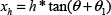
The height h of the mirror to the ground field and the radius r of the ball are known in advance. We assume that the distance between the centre of the ball and the centre of the robot is i in the panoramic image. According to the calibration results of the distance map for our omnidirectional vision system [16], we can calculate xb = f(i), where f(•) is the calibrated distance map function. According to equations (1)~(8), xl and xh can be computed, and then the length of the imaging of the ball can be approximated to be (xh − xl)·i/xb in the radial direction of the panoramic image.
Accordingly, we define a series of rectangular sub-windows to search for the ball in the panoramic image. If the distance between the centre of the sub-window and the robot itself is i, the length of the sub-window is (xh − xl)·i/xb along the radial direction and the width of the sub-window is 20, then the same applies as in Section 4.1. After rotating these sub-windows 360°, the whole panoramic image can be searched. With the ball's recognition, the sub-windows also need to be rotated to the fixed direction and then normalized to become new rectangles with a dimension of 20*20 pixels, which is the same as in the phase for the offline training. Finally, the modified Haar-like features selected in the offline training process are extracted from the new rectangles to be used as the input of the learned classifier.
The output of the classifier is a value H. If H > 0, a ball is detected in the sub-window. If H ≤ 0, there is no ball in the sub-window. Furthermore, the absolute value of H represents the reliability of the classification result. In the actual application there is only one ball on the field, so after searching the whole image, only the maximal value HMAX is considered. If HMAX > 0, the ball is detected in the related sub-window and the centre of the sub-window is the centre of the recognized ball. If HMAX < 0, there is no ball in the current panoramic image.
In the competition, there is no need to conduct the global recognition considered above by processing the whole image in every frame. Once the ball has been detected globally, we can track the ball by integrating a ball velocity estimating algorithm based on RANSAC and a Kalman filter proposed by ourselves [23]. In the algorithm, after acquiring several frames for the ball's positions, we use a Kalman filter to optimize the positions by reducing the effect of image noise. By assuming that the ball velocity is constant between frames, we calculate all the possible velocities between every two frames. Next, we randomly choose several possible velocities and calculate the average velocity as a possible velocity model. Finally, we apply the RANSAC algorithm to calculate the best velocity model as the final ball velocity from hundreds of models. Because the outliers can be eliminated effectively by using the RANSAC algorithm, the ball velocity can be estimated accurately even when the ball positions are not sufficiently accurate.
In the actual application, ball tracking is begun only when the same ball has been detected globally in three consecutive frames, as at least three frames of ball information are needed in estimating the ball velocity reliably. Moreover, some false positives caused by image noise can be eliminated from being tracked using this method, making the ball tracking more reliable. During the tracking process, the estimated ball velocity is used to predict the ball position of the next frame in the real world coordinate, and the position imaged by the predicted ball can be calculated according to the calibration results of the omnidirectional vision. Thus, we only need to process the nearby image region of the predicted ball position with the same recognition algorithm mentioned above, and the required running time can be greatly reduced. When the ball has been lost for several consecutive frames during the tracking process, the global recognition and the ball velocity estimation algorithm should be restarted.
Of course, during the current RoboCup MST competition the ball is often lifted by the robots' high kicks, but our algorithm can only deal with the situation in which the ball is on the ground. So, we have to develop a generic ball recognition method based on a stereo-vision system to solve this problem. The ball is also often occluded, either partially or totally. When the ball is temporarily occluded, the tracking algorithm will redetect the ball by using the ball velocity that was estimated in past frames to predict the ball position in the next frame. However, our algorithm only works well when the occlusion takes place for a short time (less then several frames), which will be validated in Section 5.3. So, we should integrate more effective tracking algorithms or other recognition methods to deal with the long-time occlusion of the ball.
5. Experimental results
In the experiment, we divided the set of example images into the training set and the testing set. There are 200 positive images and 400 negative images in the former, and 62 positive images and 158 negative images in the latter. We will first verify that the modified Haar-like features can improve the recognition performance, and then the recognition results will be presented and analysed. The real-time performance of our algorithm will also be tested and discussed.
5.1 The choice of different Haar-like features
In this experiment, we tested the recognition results when using different Haar-like features. We compared four different settings for the Haar-like features. The first is the original version, which computes the feature value only by the difference between the sum of the pixels within the white sub-rectangle and the black sub-rectangle area of the upright rectangle. The second computes the feature value by the difference and the division only in the upright rectangle. The third computes the feature value only by the difference in the upright and the rotated rectangles. The fourth is our modified Haar-like feature, which computes the feature value by the difference and the division in the upright and the rotated rectangles. We use “upright”, “upright + division”, “upright + rotated” and “modified Haar-like” to represent these four settings. In the training process, the number of the selected Haar-like features is an important factor affecting performance. The recognition rate will increase with the number in the general trend, but the increase will be very small when the number reaches a certain value. Furthermore, the real-time performance of the online recognition will decrease with the number. In the experiments, to allow for a compromise between the recognition rate and the real-time performance, we found that 300 is the best value. So, we set the number of the selected Haar-like features as 300. After learning a classifier with the training set, the recognition results are shown in Table 2 when using the testing set to test our algorithm. The average time to extract the Haar-like features from a panoramic image is also demonstrated in the table. From Table 2, we see that the recognition performance is greatly improved by using our modified Haar-like features, and the computation time needed to extract features from a panoramic image only increases by several milliseconds. In comparison with the use of “upright + division”, the increased time is used to compute the rotated Haar-like features when using our modified Haar-like features.
The recognition performance when using different Haar-like features

5.2 Recognition results
To test the recognition rate and false positive rate, we acquired ten typical panoramic images. There are 100 generic balls with different colours and textures included in these images, and the balls are not occluded by other objects. Several balls are near to - or even located on - the mark lines. Many other objects, like small cylinders and robots, are also included in the images. 98 balls were detected using our algorithm - so the recognition rate is 98%. The recognition results and some scaled-up results are shown in Figure 8 and Figure 9, respectively, where the red rectangles represent the sub-windows including a recognized ball. From Figure 8 and Figure 9, we can see that although the imaging sizes of the balls are small and quite different on the panoramic image, the generic balls can be recognized with a high successful rate by using our algorithm. However, because there are many balls in each panoramic image, and because a ball is considered to be detected if the output of the classifier H > 0 within a searching sub-window, there remain several non-ball areas that are detected incorrectly as balls. The scaled-up false positives are shown in Figure 10, where the red rectangles represent the sub-windows including a falsely-detected ball.

The recognition results using our algorithm: (left) the original panoramic images, and (right) the results

The scaled-up correct recognition results
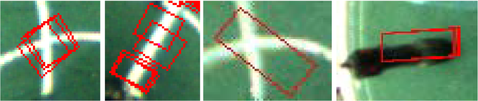
The scaled-up false positives
5.3 Ball tracking results
We also tested our algorithm after integrating the ball tracking proposed in Section 4.2. Several results in recognizing and tracking the ball in a test sequence of panoramic images are shown in Figure 11. Figures 11 (a) and (b) show the results of global recognition, and Figures 11 (c)˜(i) show the results of the tracking process. From Figure 11, we can see that the ball can be tracked effectively using our algorithm. Even when the ball was temporarily fully occluded, the tracking algorithm could redetect the ball by using the ball velocity that was estimated in the past frames to predict the ball position in the next frame.

The recognition results after integrating the ball tracking. (a) and (b) are the global recognition results, and (c)˜(i) are the recognition results during the tracking process.
5.4 Real-time performance
The RoboCup MSL competition is highly dynamic and the robot must process its sensor information as quickly as possible. We tested the running time of our recognition algorithm. The robot's computer is equipped with a 1.66 GHz CPU and 1.0 GB memory. It takes about 250˜350 ms to realize global recognition by searching a whole panoramic image. However, once the ball has been recognized globally, the running time can be reduced to be 15˜30 ms in the tracking process, as only a partial image near the predicted ball position is required to be searched. The computation time needed during a global recognition and tracking process is demonstrated in Figure 12. Because the ball tracking is run in most of the sensing cycles, our recognition algorithm meets the real-time requirement of the RoboCup MSL competition. What should be mentioned is that, in this experiment, the robot's other software modules are also working. like motion planning/control, communication, self-localization, etc.
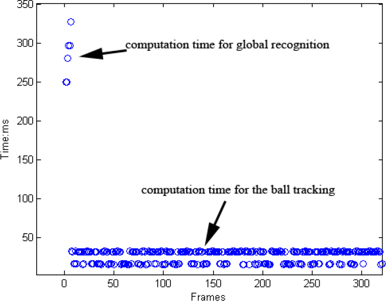
The computation time needed during a global recognition and tracking process
In our experiments, when the robot performs global recognition, it is moving at a low speed, like 1 m/s, according to the motion planning results, so that the robot can search for the generic ball around the competition field. Our robot software is realized by a multithreading programming technique, while motion control and visual perception are performed by different threads, so the high computational load in global recognition will not greatly affect the robot's other behaviours.
6. Conclusion and future work
In this paper, a generic ball recognition algorithm based on our omnidirectional vision system was proposed by combining Haar-like features and the AdaBoost learning algorithm. During the offline training phase, the traditional Haar-like features were modified, and then extracted from the sub-images for training and used as the input of the AdaBoost learning algorithm to acquire the classifier for recognizing generic balls. During the online recognition phase, a series of rectangular windows were defined to search for the generic ball along the rotary and radial directions in the panoramic image, and the learned classifier was used to judge whether a ball was included in the window. After integrating a ball velocity estimating algorithm to realize the ball tracking, the computational cost of our algorithm can be reduced greatly. The experimental results show that good performance can be achieved by using our algorithm, and the generic ball can be recognized and tracked effectively in real-time. We used the proposed algorithm to participate in the technical challenge, and achieved 3rd place in RoboCup 2010 Singapore, and 1st place in the 2010 and 2011 RoboCup ChinaOpen. In the technical challenge, the robot should search for the generic ball around the competition field and kick it into the goal, or else two robots should cooperate by passing and intercepting an arbitrary FIFA ball. Two typical processes that our team employed in participating in the technical challenge are shown in the two image sequences of Figure 13. The results also show that our algorithm works well when the robot and/or the ball are moving.
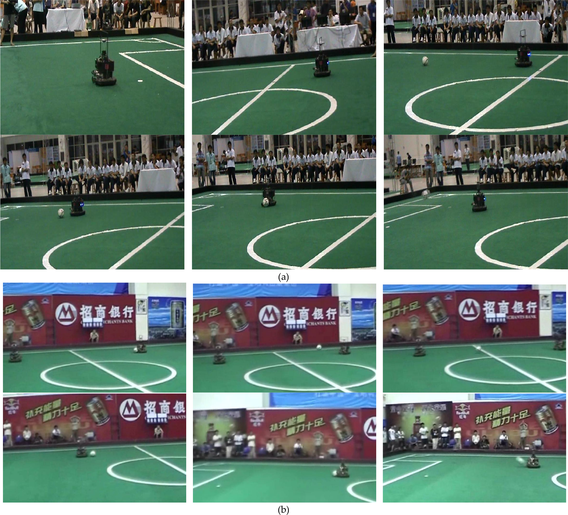
The application results of our generic ball recognition algorithm. (a) The robot searched the generic ball around the competition field and kicked it to the goal in the technical challenge of the 2010 RoboCup ChinaOpen. (b) One robot passed the generic ball, and another robot intercepted the ball, and then kicked it to the goal in the technical challenge of the 2011 RoboCup ChinaOpen.
In the next work, more effective tracking algorithms or other recognition methods should be integrated into our algorithm so that the robot can recognize and track the ball more effectively even when the ball is occluded more frequently or for a longer time, because our algorithm can work well only when the ball is not more than temporarily occluded. Furthermore, recognizing the generic FIFA ball in a three-dimensional space should be researched, because our algorithm can only deal with the situation where the ball is located on the ground of the field, yet the ball is often lifted up by the robots' high kicks during the current RoboCup MST competition.