
Abstract
A kinematics analysis of a biologically-inspired biped robot is carried out, and the trajectory of the robot foot is understood. For calculating the pressure distribution across a robot foot before touching the surface of water, the compression flow of air and the depression motion of the water surface are considered. The pressure model after touching the water surface has been built according to the theory of rigid body planar motion. The multi-material ALE algorithm is applied to emulate the course of the foot slapping water. The simulation results indicate that the model of the bionic robot can satisfy the water-running function. The real prototype of the robot is manufactured to test its function of running on water. When the biped robot is running on water, the average force generated by the propulsion mechanism is about 1.3N. The experimental results show that the propulsion system can satisfy the requirement of biped robot running on water.
1. Introduction
Work such as military surveillance, water quality monitoring, wetland detection, and searching and rescuing in complex environments need a robot with an amphibious function. The technologies of legged robots walking on hard land surfaces are relatively mature, so the study of mechanisms of legged robots walking on different kinds of material surfaces - such as water and soft sand – has become a research hotspot in robotics to extend their scope of motion.
When a basilisk lizard runs on water, its feet press the water to go down or spread out, and an air pocket will come into being above and around them, which produces the lift force overcoming their weight and the forward thrust for running on water. Compared with the movement method of a steamboat, the above method can greatly improve the driver's efficiency, since the viscous drag force of the water is decreased. A quadruped robot was designed to imitate a water-running function, and the parameters of the robot, such as feet size and the leg length, were calculated and optimized[1]–[3]. The robot will serve in martial reconnaissance, monitoring water quality, exploring marshes and rescuing lives in floods, and so on[4]. However, the robot feet move with a constant angle, which increases water resistance and reduces the robot's payload (50g).
A novel biped robot has been brought out to simulate the water-running function of basilisk lizards. The research results are helpful to develop amphibious biped robots[5]. When the robot feet slap water, the fluid-structure interaction between the feet and the fluid must be considered to obtain the lifting force of the biped robot.
In this paper, the fluid-structure interaction dynamics' analysis is carried out to get the reaction pressure of the water surface. A fluid-structure interaction theory model is built by taking account into the compression flow of the air and the depression motion of the water surface in cylindrical coordinates, where the deformation of the foot has been ignored.
2. Kinematic Analysis of The Biped Robot
Ref. 5 shows the virtual prototype of the biped robot running on the water surface, which is shown in Fig. 1. For imitating the trajectory and function of the lizard's foot, the propulsion mechanism of the robot is composed of a changed Watt-I linkage.
In Fig.1, the driving system is composed of a motor and a reducer fixed to the main frame, and the transmission agent includes a bevel gear pair and a transmission shaft. The bevel gear pair turns the driving motion perpendicular to the rotational motion around the shaft, and the driving torque is passed to the two lifting and propulsion mechanisms. A balance apparatus is fitted on the rear of the robot's frame, which can keep the robot balanced when it is walking on water.
The propulsion mechanism of the robot is designed as a controllable planar six-bar linkage with a single driver, which is shown as Fig. 2. The linkage is fixed on the point A and the point D on the ground; the World Coordinate System is shown as xAy, and the coordinate system x′Ay′ is built by taking the point A as the origin and the line AD as the x′-axis. The angle between the x′-axis and the x″-axis is θ. In the linkage, the double bar Assur Group EGF links the connecting rod BC and the output rod CD of the grounded four-bar linkage ABCD.

Virtual Prototype of a Biped Robot Running on Water

Skeleton of the Robot Propulsion Mechanism
The rods of AB, BC, CD and AD constitute the grounded four-bar linkage, whose lengths are represented by l1, l2, l3 and l4 respectively. Suppose that the angles between the rods AB, BC, CD and the x′-axis are φ1, φ2 and φ3 respectively. The rod AB is the driving rod with a constant angular velocity of ω. So, the angular displacements can be known as following, respectively [6]:

where M = l4 – l1 cos φ1, N = –l1 sin φ1 and
A new coordinate system x″Cy″ is built by setting the point C as the origin and the rod CF as the x″-axis, and the angle between the x′-axis and the x″-axis is determined as:

The rods of CE, EG, GF and FC constitute a four-bar linkage as well, and the lengths are represented as s2, l5, l6 and k3 respectively. The rod CE is looked as the driving rod. Moreover, suppose the angles between the rods EC, FG, EG and the x″-axis are φ5, φ6 and φ7 respectively, so the angular displacements can be determined as:

where H = k3 − s2 cosφ5, J = −S2 sin φ5 and
So, the trajectory of the point G in the coordinate system x″Cy″ can be deduced to be:

In addition, the trajectory of the point G in the coordinate system x′Ay′ can be determined according to the transformation formulas of the coordinates:
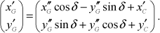
So, the trajectory of the point G in the World Coordinate System xAy can be determined as:

The trajectory of the point G is shown as Fig. 2.
3. Dynamic Analysis of the Fluid-Structure Interaction of The Robot
3.1 Equations and Press Distribution of the Air Layer before Touching Water
The flotage and driving force are produced in the stroke and slap phases as basilisk lizards run on water [5], and the air pocket comes into being during the two phases. The fluid-structure interaction for the robot running on water should be discussed to display the pressure distribution of the robot feet. Suppose that the robot feet are rigid bodies, and slap the water surface horizontally. The driving force and torque applied on Linkage BD by the running mechanism are:

where
To get the pressure distribution of a robot foot at any time, the compression flow of the air and the depression motion of the water surface are considered and the deformation of the circular feet is ignored; finally, every step length is solved by the numerical method in cylindrical coordinates.

Pressure Model before Touching Water
The cylindrical coordinates are built as in Fig. 5. The foot radius is R=l5/2, and the rotational angle of the foot can be ignored in the section of h/R<<1, and so the air flow is looked as one-dimensional movement. Suppose that the air velocity is u(r, t), then the air layer thickness from the foot to water surface is h(r, t), the height of free water surface is y′=η(r,t), the air pressure is P(r, t), the atmospheric pressure is P0, the air density is ρ(r, t), and the air density at normal atmospheric pressure is ρ0. The air viscosity is ignored, and the air is supposed to be in isentropic compression - that is, P/P0 = (ρ/ρ0)γ - so the movement equation and the continuity equation of the air are[9]:
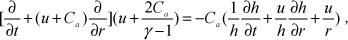
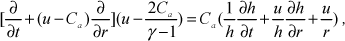
where γ is the temperature index and Ca is the local velocity of sound.
Suppose t=0 when the foot is parallel to the water surface:

where V(t) is the foot falling speed, V0 is the foot falling speed when t=0, and h0 is the air layer thickness when t=0. At this time:

So:


where:

is the water wave equation. In this equation, ρl is the density of water and J0 is a zero-order Bessel function.
Since the air flow speed under the foot is much less than the sound speed, it can be supposed that the air is uncompressible at this moment and the water surface is not disturbed. So, according to the continuity equation and the foot centre point condition u(0,t) = 0, the air flow speed can be determined as:

Based on the air motion equation and the foot edge condition P(R, t) = P0, the pressure distribution of the foot can be determined as:
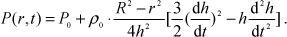
where


and:

where C0 is the sound velocity at normal atmospheric pressure.
Because the foot is not moving at a high speed, the flow speed of the air at the edge of the foot is not over the speed of sound where P(R, t)=P0. So:

where t' satisfies the equation u(R, t') =C0.
3.2 Basic Equations after Touching Water
Suppose that the edge of the foot will touch water when t=t1, and that:
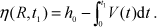
Pressure Model after Touching Water
The calculation model after touching the water surface is built as Fig. 8 by ignoring the air escaping from the bottom of the foot. According to the theory of the plane motion of a rigid body, the motion equations are as follows:

where v5y' is the y'-component of the centroid velocity of the foot in the cylindrical coordinates, which can be determined by the coordinate transformation of the ycomponent of v5, and vr is the r-component of the centroid velocity of the foot. So, the pressure distribution of the foot is:

In addition, the fluid motion equations under the foot are:

and

where:

3.3 Numerical Simulation and Prototype
The explicit dynamics' analysis has been applied for the dynamic emulation of a foot slapping water, in attempting to achieve a more exact result. Because two kinds of fluid media - water and air - are involved, the multi-material ALE algorithm has been taken to emulate the movement of the fluids, and the single-point Euler/ALE multi-material method has been applied as the unit algorithm. A multi-material unit means the flow among various materials is permitted in the mesh generated by this kind of unit, so various materials may be included in a mesh and the transport equations of various materials in the mesh should be solved in the algorithm. The foot is supposed as a rigid body, whose deformation has been ignored, and the Lagrange algorithm is applied for the emulation of the foot's structure dynamic.
The contour map of the fluid density at a certain time while running on the water's surface is shown in Fig. 5.

Contour Map of the Fluid Density
In Fig.5, the upper part is full of air and the lower part is full of water. The water surface fluctuation and the variety of the fluid density are shown in this figure.
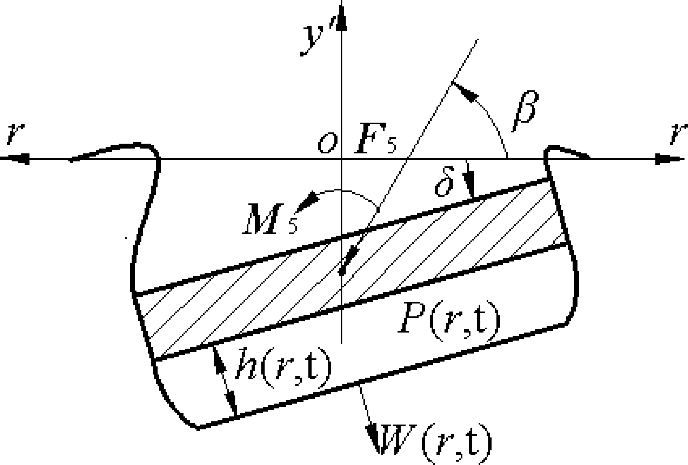
The contour map of the pressure distribution of water is shown as in Fig. 6.
The distribution of the pressure applied on the water's surface by the foot is shown as in Fig. 7.
It can be seen that the maximum pressure applied on the water's surface by the foot is at its edge.

Contour Map of the Pressure
Pressure Applied on the Water by the Foot

Force Curve during the Robot's Walking on the Water's Surface in the Simulation Environment
It can be seen from the above analysis that while the robot is running on water, the foot slaps the water's surface to pressurize the water to go down or spread out around them. At the same time, an air pocket comes into being above and around the foot. So, the slap action produces the lift force to overcome the robot weight and the forward thrust to achieve water walking, which is the same as with a basilisk lizard running on water.
The force curve in a stride can be determined according to the above simulation, which is shown as in Fig. 8.
4. Experiments and Discussions
4.1 Manufacture of the biped robot prototype
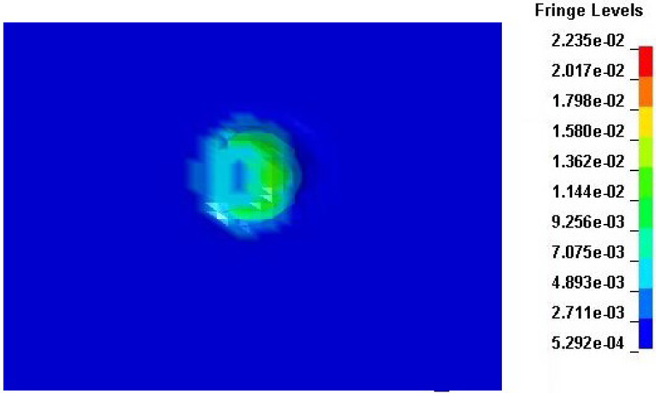
In consideration of the functional requirement of the biped robot running on water, the main body frame and propulsion mechanism must be sufficiently light. So, the aluminium alloy LY12 is taken as the material of the main body frame and the propulsion mechanism. The drive module MAXON 221011+134161 is chosen as the drive system of the robot, whose rated power is 5W and whose rated torque is 0.15 Nm. In addition, flexible rubber has been used to make the robot feet. The prototype of the biped robot is shown as in Fig. 9, whose total weight is 3.2N.
Prototype of the Biped Robot Walking on Water
The sequence diagrams of the robot walking on water are shown as in Fig. 10. The robot can walk on water due to the lifting and propulsion force produced by the legs slapping from 1 s to 4 s. The power supply is cut off as soon as the time is 4 s, and the robot stops slapping and begins to sink into the water. Ultimately, the robot will sink totally when the time is 6 s.

Sequence Diagrams of the Robot Running on Water

Force Curve Measured by the Strain Gauge
The propulsion force is the decisive factor of the robot's load capacity - that is, the force is larger and its load capacity is stronger. The lifting and propulsion force of the robot is tested. Strain gauges on both soles have been mounted on the feet, and the voltage variation of one of the strain gauges is shown by an oscillograph, from which the lifting and propulsion force can be determined. In addition, the curve of the lifting and propulsion force is shown as in Fig. 11.
The force curve in Fig. 11 is similar to the force curve in the simulation environment shown as in Fig. 8. The peak value of the lifting and propulsion force in Fig. 11 is 2.6 N, which is less than the force value of 4 N in the simulation environment. Furthermore, the valley value of the force in Fig. 11 is about 0.8 N, which is less than the value in Fig. 8 of 1.3 N as well. The simulation force values are bigger than the realistic ones because the transmission efficiency, the pressure of the atmosphere and the deformation of the soles are not considered in the simulating process.
5. Conclusion
The function of a biped robot walking on water is studied in this paper, offering the theoretical and design basis for developing a bionic amphibious biped robot. The next work will be as follows:
① The model of the amphibious biped robot will be built to promote the movement flexibility and environmental adaptability of the robot as with amphibians;
② The composite propulsion mechanism of the amphibious biped robot will be designed, and the propulsion movement on land and water will be implemented by using different modes of motion and the control of the mechanism;
③ The motion control method of the amphibious biped mechanism will be studied to implement the control method of the robot motion mode, such as going straight, turning and avoiding obstacles.
Footnotes
10. Acknowledgments
This work is supported by the National Natural Science Foundation of China (No. 50905175), and the National Programme on Key Basic Research Project of China (No. 2011CB302106).