
Abstract
Micropumps are the most important components of lab-on-a-chip devices, which are becoming popular recently due to their enormous advantages. Among the different designs of micropumps, the nozzle–diffuser valveless design is the most preferred one due to simplicity in manufacturing. For the simulation of these pumps, the local fluid–structure interaction modeling is important to get the performance accuracy. To capture fluid–structure interaction accurately, an appropriate selection of the fluid as well as the structural modeling approaches are very essential. It is well known that the polydimethylsiloxane materials behave as a viscoelastic material. However, most of the earlier studies on polydimethylsiloxane micropump modeling have considered polydimethylsiloxane as a linear elastic material. In this article, a nozzle–diffuser-based valveless micropump is modeled using a fluid–structure interaction approach along with a linear viscoelastic model for polydimethylsiloxane. The mechanical properties of the polydimethylsiloxane material are experimentally obtained using dynamic mechanical analysis for the range of micropump operating frequencies. These viscoelastic properties of polydimethylsiloxane, with varying proportionate of curing agent, are introduced in the fluid–structure interaction model of micropump using the Kelvin–Voigt model. The results are presented in the form of micropump performance parameters such as diaphragm deflection, von-Mises stresses, swept volume, and fluid flow rate.
Keywords
Introduction
Polymers comprising of elastomers, plastics, and fibers are nowadays being widely used in microelectromechanical system (MEMS) applications. Polymer materials provide many advantages regarding cost, mechanical properties, and ease of processing. Polymer materials, particularly the polydimethylsiloxane (PDMS), have advantages of fabrication simplicity, high compliance, low cost, and excellent biocompatibility when compared to silicon. 1 PDMS is considered to be the most suitable and adaptable material for soft lithography because of its optical transparency, biocompatibility, and flexibility. However, most of the research work on PDMS is focused on the development of the products and microfabrication. Therefore, there is a need for focusing on detailed modeling and simulation of these structures. The two major approaches used in the design of micropump are valve-type micropumps and valveless micropumps. Valveless pumps are the usually preferred due to their ease of manufacturing and consistency in performance. Therefore, there is a need for pumps with no moving parts. 2
Experimental characterization of PDMS was focused on the estimation of viscoelastic properties and study of nonlinear behavior. Kim et al. 3 measured the nonlinear mechanical properties of PDMS elastomer based on the mixing ratio of base polymer to curing agent. The findings of this study indicate that when PDMS is mixed with an excessive curing agent, stress softening occurs and residual strain exists in cyclic tension tests. Vanlandingham et al. 4 studied the use of instrumented indentation to characterize the mechanical response of PDMS material. The study indicates that the mechanical response of viscoelastic materials is highly dependent on the type and level of stresses and strains as well as the strain rates. White et al. 5 distinguished the dynamic mechanical response of PDMS polymeric materials with the response obtained with more traditional bulk techniques.
Numerical modeling of PDMS elastomer at micro-level is another area of interest. Lin et al. 6 modeled PDMS as a viscoelastic material for biological applications. They emphasized the importance of modeling of PDMS as a viscoelastic material. Furthermore, they have compared the performance of biological components with and without viscoelastic consideration.
Moravec and Letzelter 7 carried out a simulation to observe the viscoelastic behavior during quasi-static equilibrium processes using COMSOL Multiphysics software. The results obtained from these simulations are compared with experimental data for creep and relaxation tests performed on the samples of biological tissues.
Ouyang et al. 8 demonstrated the variation of PDMS properties for developing a tunable grating. The PDMS material properties were tuned by modifying the network structure to get good actuation of the polymer, including large relief depth and fast response speed. Similarly, Schneider et al. 9 systematically studied the mechanical and optical properties of the most commonly used PDMS materials.
Micropump studies have been carried out extensively over last decades focusing on design approaches, fabrication processes, and actuation mechanisms. 10 Olsson et al. 11 introduced a multiple chamber valveless micropump with planar structure (planar nozzle–diffuser type), which made it easier to incorporate in MEMS devices. Singhal et al. 12 investigated the flow characteristics of low Reynolds number laminar flow through gradually increasing planar and conical diffuser elements. These diffusers are used in valveless micropumps to obtain flow rectification, which leads to pumping action in preferred direction. Zhou and Amirouche 13 reported a PDMS-based electromagnetically actuated micropump, including a pair of microdiffuser and nozzle, elements used for rectifying the fluid flow, and an elastic magnetic membrane used to regulate the pressure in the enclosed fluid chamber. Cui et al. 14 studied the electric–fluid–solid coupling model to investigate the behavior of the micropump using ANSYS software. Yao et al. 15 carried out computational fluid dynamics (CFD) simulations for the flow in valveless micropumps. Fan et al. 16 presented numerical studies for a piezoelectric valveless micropump with consideration of the three-way electromechanical–fluid couplings.
The diaphragm used in the micropump application must have large deflection in order to reduce dead volume in pump chamber as well as for increasing the flow rate of micropump. To satisfy these requirements, the diaphragm must be fabricated with soft polymers and highly compliant biocompatible PDMS. The viscoelasticity and the related phenomenon are of great importance in the study of biological materials. Moreover, PDMS is a viscoelastic material, and its storage modulus and loss modulus change with the loading rate and the elapsed time. Neglecting these characteristics of PDMS can result in errors while evaluating the actual performance of micropump. Therefore, an accurate viscoelastic characterization of PDMS materials of different proportion is of vital importance to carry out performance analysis of a micropump. In order to deal with the above-mentioned need, the viscoelastic characterization of PDMS material and simulation of PDMS-based micropump are necessary. From the above literature review, it is clear that experimental investigations and numerical analysis of valveless micropumps including its fabrication have been reported by many researchers. However, the fabrication of diaphragm based on the varying proportion of PDMS base material and curing agent as well as a comprehensive study of viscoelastic properties of the PDMS diaphragm that influence micropump performance have not been addressed by researchers.
With the intension of studying the influence of viscoelasticity on micropump performance, the viscoelastic properties of PDMS materials with four configurations are estimated using dynamic mechanical analyzer (DMA). The valveless micropump is modeled using COMSOL Multiphysics software capable of modeling fluid–structure interaction (FSI) and viscoelastic material behavior. The viscoelastic material properties of PDMS material are introduced in micropump modeling using Kelvin–Voigt model. Performance of diaphragm in FSI and fluid flow performance of micropumps with and without consideration of viscoelastic effects are compared.
Theoretical background
The viscoelastic materials exhibit both viscous and elastic characteristics when during deformation. Long molecular chains in polymer materials like PDMS contribute to their unique viscoelastic properties, that is, a combination of the features of both elastic solids and Newtonian fluids. Stress, temperature, frequency, and other factors all play role in the viscoelastic properties of polymers.
Viscoelasticity
The phenomenon of exhibiting both elastic and viscous properties is known as viscoelasticity. For an elastic material, the relationship between stress and strain can be expressed in the following form 17

Equation (1) states that the normal stress (σ) is a function of the normal strain (ε) only. For a linear elastic material, stress is linearly proportional to strain. However, the relation between stress and strain in the viscoelastic material can be expressed as given below

Equation (2) states that stress (σ) is not only a function of strain (ε), but also a function of the strain rate;
Complex shear modulus
The relationship between the complex modulus and other properties is shown in Figure 1. The relation between complex shear modulus obtained from a dynamic mechanical test, storage modulus, and loss modulus can be expressed as follows

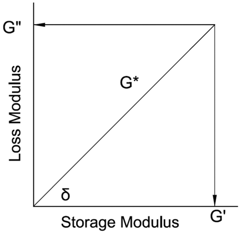
Complex shear modulus (G*), real (G′), and imaginary (G″) moduli and phase difference (δ).
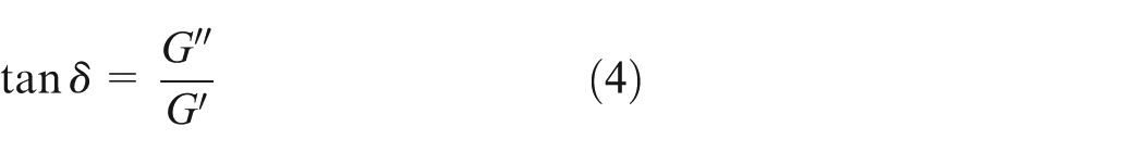
In addition, loss tangent (tan δ) related to loss and storage modulus is as follows 18
Viscoelasticity modeling
Empirical models are obtained by connecting a spring and a dashpot together in parallel and in series configurations. The schematic illustrations of the linear elastic model, which includes only spring and the Kelvin–Voigt viscoelastic model and which includes a parallel spring–dashpot element to account for the viscous behavior of material, are shown in Figure 2(a) and (b), respectively.
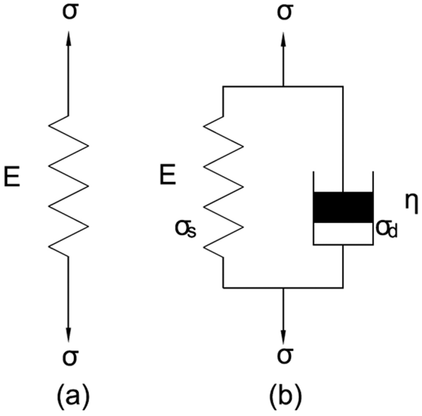
(a) Linear elastic model and (b) Kelvin–Voigt viscoelastic model. 17
The total stress (σ) in the system and the strain (ε) of the system can be expressed as follows
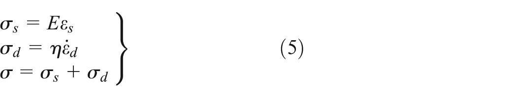

For a given stress (σ), the equation is then expressed as follows 17

Equation (7) represents stress–strain relationship and the strain rate for two parameters (E and η) of viscoelastic model. Dynamic viscosity (η) is used to describe the viscous behavior of the single dashpot in Kelvin–Voigt model. Hence, it can be used to describe viscous behavior of PDMS. The relationship between dynamic viscosity (η) and the loss modulus (G″) can be expressed by equation as follows 18

Dynamic viscosity (η) may only be used in ranges where the material exhibits the viscous behavior. Therefore, to describe the viscoelastic behavior of materials like PDMS, the dynamic viscosity (η) is an appropriate measure.
Dynamic viscosity for various configurations of PDMS
In the study, the dynamic viscoelastic properties of various configurations of PDMS are obtained using DMA, which is explained in following sections. Understanding the usage of the PDMS with different mixing ratios of the base polymer and curing agent is vital. The PDMS samples were prepared using Sylgard 184, with four mixing configurations of base polymer:curing agent as 6:1, 7:1, 9:1, and 10:1. The length, width, and thickness of the PDMS samples were 40, 40, and 2 mm, respectively. The fabricated PDMS samples are tested using DMA. For the characterization of the viscoelastic properties of PDMS, first an amplitude sweep is run in a shear deformation mode. According to the results of the amplitude sweep, a deformation of 0.01 is selected for the frequency sweep. A wide range of frequencies have been used starting at 50 Hz and going down up to 5 Hz. As micropump simulations are performed at moderate frequency range, heat generated due to friction is negligible. This heat will also get dissipated due to fluid flow during pumping cycle. Therefore, the influence of temperature on PDMS properties is not considered. DMA tests are performed at constant temperature of 25°C.
Storage and loss modulus of PDMS
The effect of the PDMS mixing ratio on the viscoelastic moduli as a function of oscillation frequency and the corresponding moduli with respect to oscillation frequency is shown in Figures 3 and 4 for four PDMS configurations. These viscoelastic characteristics are material specific, and their magnitude depends critically on the frequency as well as the measuring conditions. It could be seen from Figure 3 that the tested PDMS samples show a consistent trend with the oscillation frequency. The similar trend was observed for the loss modulus also as shown in Figure 4. The viscoelastic moduli increase as the mixing ratio increases. Thus, the viscoelastic moduli depend strongly on the mixing ratio and these moduli increase as the mixing ratio increases and reach a maximum value corresponding to a mixing ratio of 10:1.

Effect of the mixing ratio on the storage modulus.

Effect of mixing ratio on the loss modulus.
Dynamic viscosity and material constant
Dynamic viscosity (η) can be computed from the preceding DMA using equation (8) and is summarized in Table 1. It can be seen that the dynamic viscosity of PDMS samples decreases with an increase in the oscillation frequency. It is also observed that the dynamic viscosity shows a consistent trend with the oscillation frequency. The density of the PDMS material is 970 kg/m3.
Summary of computed dynamic viscosity.

Material constants obtained from DMA data are shown in Table 2. Another interesting point is that as the ratio of base polymer increased in PDMS, Young’s modulus and modulus of rigidity of PDMS increase. As modulus of elasticity is influenced by degree of crosslinking between base polymer and curing agent, these values increase with increase in base polymer. 19
Material constant obtained from DMA data.

PDMS: polydimethylsiloxane.
Numerical modeling of micropump
The numerical modeling of the micropump with viscoelastic properties of PDMS material obtained in previous section is performed using commercially available numerical software COMSOL Multiphysics 5.0 which is capable of performing fluid flow analysis, solid mechanics analysis, and coupling between both these analyses. This software is also capable of including the effect of viscoelasticity in the constitutive relation using Kelvin–Voigt model. The brief description about the background of numerical modeling, geometric details of micropump model, and boundary loading conditions is given in this section.
FSI modeling
In the FSI approach, fluid flow described using Navier–Stokes equations is combined with the solid mechanics at the interface of FSI boundaries. The physics interface uses an arbitrary Lagrangian–Eulerian (ALE) method to combine the fluid flow formulated using an Eulerian description and a spatial frame with solid mechanics formulated using a Lagrangian description and a material (reference) frame.
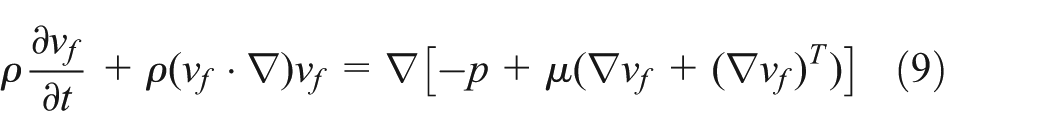
The single phase fluid flow physics interfaces in the absence of heat transfer are governed by two sets of equations 20

The predefined fluid–solid interface boundary condition includes these couplings for bidirectionally coupled FSI simulations:
Displacement boundary condition
Force boundary condition


The equation of motion for solid mechanics part is obtained using the first Piola-Kirchhoff stress tensor as

The tensor divergence operator ∇ is computed with respect to coordinates of material frame.
The Cauchy stress D can be calculated as follows

where strain–displacement relationship matrix B is given as follows


Similar to the analogy of introducing the viscoelastic part shown in equation (7), the stress matrix σ for three-dimensional (3D) model using elasticity matrix C and strain rate dε/dt can be given as follows

The spatial frame also deforms with a mesh deformation that is equal to the displacements u of the solid within the solid domains. The mesh is free to move inside the fluid domains, and it adjusts to the motion of the solid walls. This geometric change of the fluid domain is automatically accounted for in COMSOL Multiphysics by the ALE method. 20
Micropump structure and meshing
In general, nozzle–diffuser-based micropumps are constructed using a diaphragm, which oscillates periodically and thus generate periodic volume variation in the chamber. The diaphragm is used to generate a pressure difference across the nozzle–diffuser element at the inlet and outlet during supply and pumping modes. A schematic nozzle–diffuser-based valveless micropump model is presented in Figure 5. The details regarding dimensions of micropump are shown in Table 3.

Schematic of the valveless micropump.
Design parameters for the micropump.

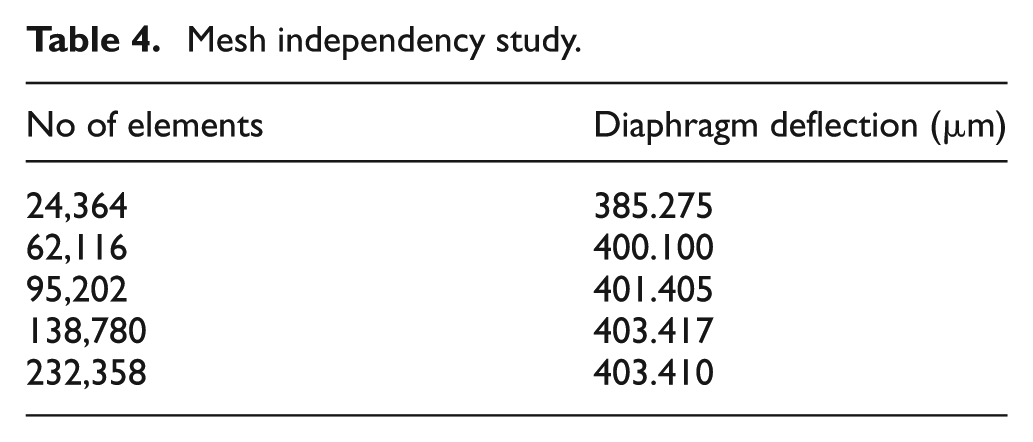
The model of the micropump is built in COMSOL Multiphysics 5.0. The whole micropump model consisting of the structure and fluid domains are meshed using tetrahedral, prism, pyramid, and triangular elements as shown in Figure 6. Mesh independency study has been carried out for the linear elastic model of PDMS 10:1 at 5 Hz actuation frequency and results for diaphragm deflection are shown in Table 4. The total number of mesh elements considered in the study is 138,780.
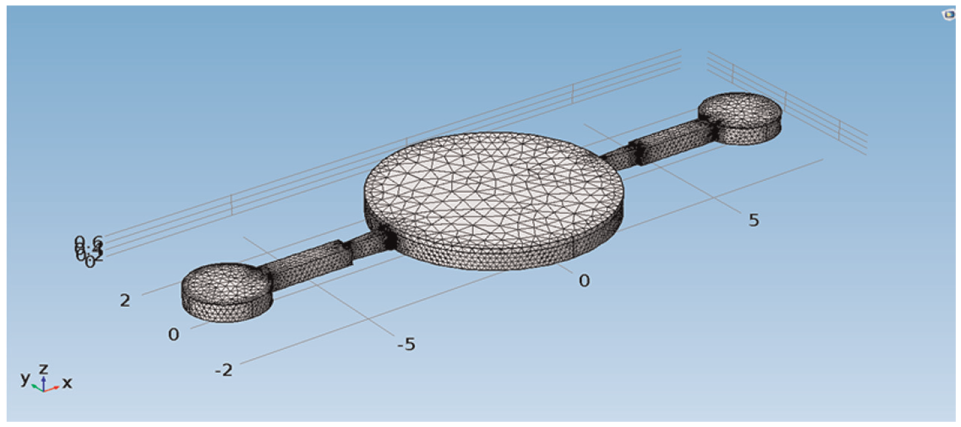
Model of the valveless micropump with meshes.
Mesh independency study.
Boundary conditions
PDMS diaphragm is fixed at its edges and considered as a zero displacement boundary condition. A sinusoidal pressure with amplitude of 1 kPa is applied to the PDMS diaphragm for actuation

The boundary conditions for fluid model are no-slip at the fluid–wall interface and FSI and pressure boundary conditions at both inlet and outlet of the micropump. The flow is considered to be incompressible.
Performance analysis of micropump
The linear elastic and linear viscoelastic micropump models are used for performing simulations. In the modeling of micropump with linear elastic constitutive relation, the strain rate term in equation (18) is not considered, whereas for modeling it with viscoelasticity, the complete equation is considered.
For all the simulations, the amplitude of actuating pressure is considered as 1 kPa and results are obtained by varying the actuating frequency. Figure 7 shows the deflection pattern of diaphragm, von-Mises stresses in diaphragm, streamline velocity field, and inlet–outlet flow rate of one cycle for 5 Hz excitation frequency for linear model. The deflections, stresses, and streamline patterns vary with respect to time, and Figure 7(a)–(c) shows the representative surface plot of particular time. These figures are shown as indicative of surface plots of responses at a particular time and all further results are presented as maximum values of these performance indicators. The simulation result shows that the deflection is the maximum at the center and zero at the edges, as expected theoretically as shown in Figure 7(a). During the supply mode, the diaphragm deflects upward creating a negative pressure inside the pump chamber. Due to this, the fluid enters the pump chamber through the inlet and outlet. While during the pump mode, the diaphragm deflects into the pump chamber, thus increasing the pressure of the fluid within the pump chamber. As a result, the fluid from the pump chamber exits through the inlet and outlet. However, a flow rectification occurs due to the pressure difference across the nozzle and diffuser element which are connected between pump chamber and inlet–outlet. 21 The net flow of the pump is resultant of the inlet and outlet flow of the flow rate plot with respect to time as shown in Figure 7(d).

(a) Deflection contours showing the variation of the magnitude of deflection, (b) von-Mises stress distribution in the diaphragm, (c) streamline velocity field inside the micropump, and (d) variation of the fluid flow through inlet and outlet.
Deflections of diaphragm
The deflection amplitudes of the diaphragm in the pumping process during FSI are shown in Figure 8. These figures show the influence of consideration of viscoelasticity on the deflection of diaphragm. The slight variation in the effect of viscoelasticity on the deflection performance is observed with respect to excitation frequency and material properties of PDMS. As Young’s modulus increases from PDMS of 6:1 mixing ratio to PDMS of 10:1 mixing ratio (Table 2), the diaphragm deflections are expected to show proportional decrease. However, as this deflection is not of the empty pump diaphragm, such proportional decrease in the diaphragm deflection amplitude may not be possible. This also gives an indication that the diaphragm deflection is mostly dominated by dynamic pressure imposed on the diaphragm by the fluid as a result of FSI.

Comparison of diaphragm deflection for proportion: (a) 6:1, (b) 7:1, (c) 9:1, and (d) 10:1.
von-Mises stress of diaphragm
In the design of any component, it is often important to characterize the effective stress developed in the critical components. The von-Mises stress is one of the failure criteria applicable for isotropic material. As the micropump operates under dynamic loading, the maximum values of von-Mises stresses at various excitation frequencies are plotted in Figure 9 for four different PDMS configurations. Similar to deflection response, the von-Mises stresses of diaphragm are also reduced slightly. Although the deflection amplitudes are dampened by internal fluid of the pump, the effect of increase in Young’s modulus due to increase in base polymer increases the von-Mises stresses.
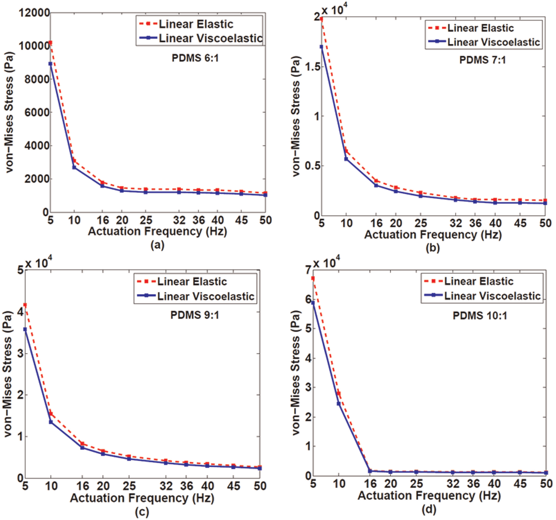
Comparison of von-Mises stress of PDMS diaphragm for proportion: (a) 6:1, (b) 7:1, (c) 9:1, and (d) 10:1.
Swept volume
The amplitude of swept volume of micropump for linear elastic and viscoelastic assumptions for various excitation frequencies are shown in Figure 10 for different configurations of PDMS. As compared with diaphragm deflection and von-Mises responses, the viscoelastic effect on swept volume is considerable.

Comparison of swept volume as a function of the actuation frequency for proportion: (a) 6:1, (b) 7:1, (c) 9:1, and (d) 10:1.
This increase in variation of the swept volume is influenced by the effect of viscoelasticity on the amplitude of diaphragm as well as the lag between inlet–outlet flow. It is also observed that the swept volume becomes the minimum for PDMS with mixing ratio of 10:1 and increases with a decrease in the amount of the base polymer.
Flow rate
The diaphragm used in the micropump application must have large deflection in order to reduce dead volume in pump chamber as well as for increasing the flow rate of micropump. Using fluidic diodicity (ηF), the pump frequency (f), and the swept volume (ΔV), the flow rate of the pump can be estimated as follows 2

The microfluidic diodicity is evaluated as the ratio of the flow rate in the forward and backward directions in the case of constant pressure drop over the rectifying structures. This diodicity is given by equations (21) and (22) 2


In the nozzle–diffuser micropump, the backward direction is the nozzle direction and the forward direction is diffuser direction. Additionally, when ηF > 1, the pumping action takes the diffuser direction; while when ηF < 1, the pumping action takes the nozzle direction.
The estimated fluidic diodicity of the nozzle–diffuser structure which characterizes the performance of the micropump is 1.128 which is within the range (i.e. from 1 to 5) specified in the literature. 22 With the known fluidic diodicity, the pump frequency, and the swept volume, the flow rate of the micropump is computed. Figure 11 represents the effect of viscoelastic behavior of PDMS diaphragm on the flow rate of the micropump for various mixing ratios of the base polymer and curing agent at different frequencies. Although the deflection response diaphragm is not influenced considerably with inclusion of viscoelastic effects, overall flow rate is influenced considerably by 8%–10%. As the natural frequency of the diaphragm depends on PDMS mixing ratio due to change in stiffness values, the nature of interaction with natural and excitation frequency changes. The first resonating modes for the flow rate are 16, 16, 20, and 20Hz for the four material configurations of 6:1, 7:1, 9:1, and 10:1, respectively. Although the first mode frequencies are same for first two materials and last two materials, the higher modes show variations in frequencies.

Comparison of flow rate as a function of the actuation frequency for proportion: (a) 6:1, (b) 7:1, (c) 9:1, and (d) 10:1.
Conclusion
This article demonstrates the numerical modeling of PDMS micropump behavior using the FSI along with viscoelastic material model which is the appropriate assumption for PDMS material. The literature survey indicates that this work is the first effort of considering the influence of viscoelasticity in numerical modeling of PDMS-based micropumps. This study demonstrates the efforts of inclusion of viscoelastic properties obtained from DMA testing into numerical analysis for getting more appropriate simulation results.
The effects of viscoelastic properties on diaphragm behavior and micropump flow rate for various mixing ratios of PDMS and excitation frequency are studied. The performances of micropumps with viscoelastic behavior are compared that of the linear material pump behavior. Although the consideration of viscoplasticity in the modeling does not show considerable influence on the diaphragm performances, namely deflection and stresses, the flow rate performance shows the considerable influence. The flow rate performance shows reduction of about 8%–10% due to an inclusion of viscoelastic effect. As the diaphragm deflection is dampened considerably due to the internal fluid during the FSI, the influence of viscoelasticity on the deflection is minimal. However, the inlet–outlet flow lag gets affected by the viscoelasticity consideration resulting into dampening of flow rate.
This study can be extended for the modeling of the micropump with smart actuators and including the effects of fluid properties, such as viscosity and temperature on the performance of micropumps. These simulations can also be extended for analysis of PDMS-based check-valve micropumps and other lab-on-a-chip devices under dynamic loading.
Footnotes
Appendix 1
Academic Editor: Moran Wang
Declaration of conflicting interests
The author(s) declared no potential conflicts of interest with respect to the research, authorship, and/or publication of this article.
Funding
The author(s) received no financial support for the research, authorship, and/or publication of this article.