
Abstract
Stabilization of a single wheel mobile robot attracted researcher attentions in robotic area. However, the budget requirements for building experimental setups capable in investigating isolated parameters and implementing others encouraged the development of new simulation methods and techniques that beat such limitations. In this work we have developed a simulation platform for testing different control tactics to stabilize a single wheel mobile robot. The graphic representation of the robot, the dynamic solution, and, the control scheme are all integrated on common computer platform using Visual Basic. Simulation indicates that we can control such robot without knowing the detail of it's internal structure or dynamics behaviour just by looking at it and using manual operation tactics. Twenty five rules are extracted and implemented using Takagi-Sugeno's fuzzy controller with significant achievement in controlling robot motion during the dynamic simulation. The resulted data from the successful implementation of the fuzzy model are used to utilize and train a neurofuzzy controller using ANFIS scheme to produce further improvement in robot performance
Introduction
Self-stabilization of a single rolling wheel using a gyroscopic actuation was under several explorations for its importance in robotic applications (Nandy, G. C. & Xu, Y. 1998) and (Xu, Y.; Brown, H. B. &, Au, K. W. 1999). The mechanical design consists basically of a gyro disk attached to internally suspended pendulum. Such arrangement provides a forward and reverse movement in which the reaction of the applied motor torque is counteracted by the moment of the hanging mass of the gyroscope and gimbals system as shown in Figures 1 and 2. The spinning gyro of the pendulum mechanism provides the turning, as well as the static and dynamic balance using the effect of gyroscopic precession induced by the applied torque.
Recent studies (Martynenko, Yu. G. & Formal'skii, A. M. 2005) developed methodolgy to control the longitudinal motion of a single wheel robot on an uneven surface. Yangsheng Xu & Samuel, K. W. Ou (2004) developed a linear state feedback approach to stabilize a robot at any desired lean angle. A prototype is developed by Ferreira, E.; Tsai, S.; Paredis, C.; & Brown, H. (2000) and Cavin, R. D. (2001) for a single-wheeled autonomous vehicle capable of righting itself from any position, spinning about its own axis, moving forward and backward, and avoiding obstacles in its path. The platform gained feedback from the environment using a tilt sensor and electronic compass for both balancing and heading. It also included speed detection and object avoidance by using sonar sensor and shaft encoder on the main drive motor. It is demonstrated experimentally that the wheel can automatically be controlled by using the learned human control input (Samuel, K. W. Au; Yangsheng Xu & Wilson W. K. Yu. 2001). Cost of such experimental setups might represent a burden for the investigators in this area. The present work is targeting simulation tools and techniques that might result in lowering such price tag by using virtual prototyping and real time simulation in controlling such system under different manoeuvring tasks using intelligent control scheme. Visual Basic is utilized as a medium for integrating all of these components. A neural network can approximate the response, but is not capable of interpreting the results in terms of natural language. Therefore, using the neural networks and fuzzy logic in the controller design via neurofuzzy would provide both learning and response readability.

The Basic Design for the Gyroscopic Wheel

The Graphical Model for the Robot
Virtual prototyping and real time simulation are carried out by integrating different computer programs under Windows environment using Visual Basic.
Robot graphical modelling
The graphical representation of the outside shells and the gyro-pendulum are shown in Figure 2. All generated parts for the single wheel robot are drafted in separate part files. The outside shells are considered as the basic parts in the generated assembly file. All other parts are externally referenced to this assembly file and appropriate constraints between parts and sub-assemblies are added to control the motion as required.
Real time motion simulation
After the check for possible interference in graphical modelling from previous step the graphical assembly file is exported to the motion simulation software However the motion simulator may mistakenly recognise some constraints Such constraints are then corrected and the system motion is appropriately verified All motion coordinates for the moving wheel and the gyro-pendulum suspension system in the simulation file are assigned in a way similar to that of the derived equations in this work to simplify the extraction of results The dynamic equations are programmed by using the visual basic to investigate the robot motion as a result of specific external effects (as clarified in Figure 3).

Solution and simulation steps for the Gyro-stabilizing Wheel
The motion and the stabilizing actions of the wheel are based on the gyroscopic precession principle Due to its angular momentums the wheel tends to precess at right angles with the externally applied torque The fundamental equation of the gyroscopic precession is:

where T is the torque acting on the gyroscope Iω is its angular momentum and Ω. is the precession rate.
When the robot wheel forward velocity is zero, the gyroscopic effect of the flywheel can stop the robot from falling over by using the balance motor-1 in figure 2 and simultaneously induces a positive rotation around the robot vertical axis. The tilt motor-2 can be used to steer the robot to the required direction, which cause the wheel to lean to one side. The formulations of the fundamental dynamic equations are based on Lagrangian constrained generalized principle (Xu, Y.; Brown, H. B. &, Au, K. W. 1999). Other methods can be applied without using Lagrange multipliers to reduce computation complexity (Nukulwuthiopas, W.; Laowattana, D. & Maneewarn, T. 2002). More details are available for modelling a dynamic system subjected to nonholonomic constraints (Bloch, A.M. 2003)
It is more convenient to formulate this problem by assigning four coordinate frames as shown in Figure 4. These frames are used to relate the values of the dynamic variables from all other coordinates to the absolute coordinates XYZ.

Reference frames and system variables
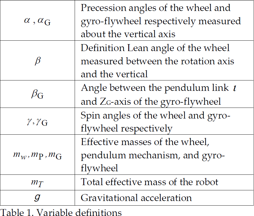
Table 1 describes the notation for the parameters that used in formulating the dynamic equations. The assigned four coordinates are the following: i) the absolute coordinates XYZ whose x-y plane is attached to the wheel surface; ii) the wheel centre body coordinate frame {xw, yw, zw} where the zw represents the wheel rotation axis; iii) the coordinate frame of the suspended pendulum mechanism is {xP, yP, zP} centred at the gyro-flywheel attachment; iv) the gyro-flywheel coordinate frame {xG, yG, zG} centred at the gyro-flywheel attachment and zG represents the gyro axis of rotation. The dynamic modelling of the robot is based on the assumptions that all of the components are rigid. Roll/slip condition for the wheel is checked continuously using a reasonable coefficient of friction between the wheel and the floor. Angular velocity of the gyro is kept constant and, both robot wheel and gyro-flywheel are modelled assuming axial symmetry. Interaction between surface irregularities and wheel surface is not incorporated in the modelling.
Variable definitions
Assuming that the vectors in the absolute and wheel body coordinates are having scalar components (X, Y, Z) and (xw, yw, Zw) respectively then,
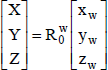
where 


If vw and ω
w
are respectively set to represent the linear and the angular velocity of the robot wheel centre of mass with respect to the absolute coordinates, then through the coordinate transformation matrices we can obtain a vector equation for ω
w
and from the no slip kinematics and equation (6) we can attain the set of Equations (3–5):

By integrating equation (5) we get,

The Lagrangian constrained generalized principle is one of the techniques used for analyzing the non-holonomic systems as in this work to derive the dynamic model for the gyroscopic wheel. Let us consider a non-holonomic system with n degrees of freedom, whose Lagrangian coordinates and velocities are qj, and, 
For nonholonomic system, the set of Lagrangian equations are then given by,
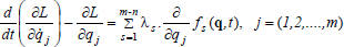
where, L = T−P is the Lagrangian function, T is the total kinetic energy of the system, P is the total potential energy of the system, and λ s is a Lagrangian multiplier that accounts for the system constraints.
The system can be divided into three parts namely robot wheel, pendulum mechanism, and, gyro-flywheel. The kinetic energy of the robot wheel is,

The potential energy of the robot wheel is

The translational and the rotational kinetic energy of the internal mechanism and the flywheel are derived by applying the transformation relation between the centre of robot wheel absolute coordinates to the gyro-flywheel centre (xG, yG, zG) described as,

The translational kinetic energy of the flywheel and the pendulum mechanism 
The internal mechanism swings slowly without a significant contribution to the system rotational kinetic energy and therefore the gyro-fly wheel would be the main provider for the rotational energy in the pendulum mechanism which is given by:

where, 
Finally the Lagrangian function of the system is

The dynamic equations for the entire system can be derived by substituting Equations (10–15) into Eq. (16). The general dynamic equation of the system is solved numerically using the Kutta-Merson integration. The solution is based on variable time step which automatically adjusts the time increment and monitor simulation errors of various types.
Because of the applied loadings, it may not be known if the robot wheel rolls without slipping or slides as it rolls. Such conditions are checked at each time increment during the robot simulation by investigating the dynamic balance between the resulted angular and linear inertia loads and the applied external torques and forces on the robot wheel using Newton's and Euler's Equations. The simulation detects collisions geometrically by finding the intersections between the bodies. When bodies collide, the simulation computes the forces and/or the impulses necessary to prevent interpenetration and applies these responses at the contact points. Based on the obtained values for these responses (forces and impulses) the program calculates the new accelerations and velocities of the bodies and continues the simulation process. The solution scheme is based on using appropriately small integration steps near collisions and employs an impulse momentum collision model with proper coefficient of restitution.
It is difficult to acquire a controller that ensures continuous trajectory tracking under stabilized condition for single wheel mobile robot under continuous exposal to an erratic real time inputs. The use of intelligent controller is generated by the random nature of system excitations which largely depends on unpredictable parameters such as friction, and other variable dynamic forces. A neural network can model the response of such system by means of a nonlinear regression in the discrete time domain. The result is a network, with adjustable weights, that might approximate the system dynamics. Though it is a problem since the knowledge is stored in an opaque fashion and the learning results in a large set of parameter values which almost impossible to be interpreted in words. Conversely using a fuzzy rule based controller that consists of readable if-then statements which is almost a natural language, cannot learn new rules alone. The neurofuzzy controller might be preferred over the others for such application since it combines the two and it has a learning architecture (Jang, J.-S. R.; Sun, C.-T. & Mizutani, E. 1997). To construct a neurofuzzy controller with ANFIS (Adaptive Neuro Fuzzy Inference System), we need a set of input-output data. In this work, two input signals are considered. The first input is the wheel orientation error (ɛβ, OrientError) which is defined as the angle of deviation between the vertical line that passes through the ground contact point and the line that connects the wheel mass centre and wheel contact point. The second input is the deviation angle between the actual wheel path and the tangent to the planned track (ɛα, DirectError). The output signals are the angular velocity of steering and balance motors as indicated in Figure 2. The gyro drive shaft is kept at constant angular velocity.
Control strategies under different design parameters that might be difficult to implement in a real experimental setup can be tested by using the dynamic simulation of ordinary Sugeno's Fuzzy controller. All problem components are integrated through visual basic as shown in Figures 3 and 5. Data set are collected for training and adapting the Neurofuzzy controller in the next stage. The cost effectiveness of such simulation is add to the important flexibility in exploring different dynamic parameters which might be difficult to introduce in actually built system.

Sugeno's Controller layout
The general Takagi-Sugeno rule structure is:
If g (e1 is A1, e2 is A2, …, ek is Ak) then
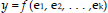
Here f is the logical function which connects the sentences that form the implemented conditions, y is the output, and, f is a function of the inputs e1, e2, …, and ek. The inputs in this work are the orientation and track errors, while the outputs are the angular velocity of steering motor and, balance motor.
The rules can be structured according to the importance of the actual parameters involved in the targeted application based on the simulated dynamic model. The Takagi and Sugeno's fuzzy model can be formulated as the following:

where, Li (i = 1,2,….n) denotes the i-th rule, n is the number of fuzzy rules, yi or fi is the output from the i-th rule (implication), 
where 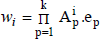
To facilitate the learning (or adaptation) of the Takagi-Sugeno fuzzy model, it is convenient to implement the fuzzy model into a framework of adaptive network that can compute gradient vectors systematically. The resultant network architecture called ANFIS (Adaptive Neuro-Fuzzy Inference System). ANFIS is described by a similar Takagi-Sugeno model with a single difference that in this case the inputs, e
1
(ɛβ-OrientError) and, e2(ɛα-DirectError) are range values. The fuzzy set for ɛβ being

ANFIS architecture
The square elements in Fig. 6 represent the adaptive nodes depending on the parameter set of the adaptive network. The circles represent fixed nodes, which are independent of the parameter set. The first layer is composed of adaptive nodes representing the triangular membership functions (Jang, J.-S. R.; Sun, C.-T. & Mizutani, E. 1997) associated with each linguistic value. The second layer implements the fuzzy rules. Each node in this layer calculates the firing strength of a rule by means of multiplication between the membership degrees of the two inputs. The third layer consists of adaptive nodes which include the output membership.
The other two layers consist of fixed nodes that implement the weighted average procedure to obtain one of the motors output y as shown in Fig. 6. As the size of the rule base of the Sugeno fuzzy inference system (SFIS) is 25, we will have to identify 75 consequent parameters
In our simulation, we investigated the robot control tactics when passing a platform of three segments namely I, II, and, III as shown in Fig. 7. Segment-I in Fig. 7 (a) is used to investigate the robot capability in climbing an uphill ground or passing obstacle with adjustable tilt angle ψ both friction and restitution coefficients between the wheel and the uphill ground can be investigated. The uphill ground represented by the segment-I is kept with zero angular twist around the pathway centreline during results extractions. Segment-II represents the middle section of the platform with adjustable level relative to segment-I to investigate the jumping behaviour of the robot. Finally segment-III is the last section of the platform and twisted with an angle λ around the pathway centreline and used to examine manoeuvrability of the robot when it is confronted with sudden slop change of ground. Throughout our simulation the following physical, geometrical and mass parameters are used as given in Table 1

Simulation platform
Parameter values as shown in Fig. 4

Throughout the simulation our interest is concentrated on the application of ANFIS as adaptive control scheme and the results are compared to the Takagi-Sugeno fuzzy model. Our attempt is to establish a strategy to stand up a single wheel robot under large orient error angle ɛβ. The trials failed either due to the high tilt rate requirement or the limited manoeuvring angle for the gyro.
Figs. 8 and 9 present the time variations in OrientError and DirectError angles for the single wheel robot under the Sugeno control.
The time variation in orient error angle for λ=10° and ψ=30° under Sugeno control

The time variation in direct error angle for λ=10° and ψ=30° under Sugeno control.
The locations S and E are indicated in Fig. 7 on the simulation platform and the angles λ and ψ are 100° and 300° respectively. Significant reductions for the variations of same angles under same simulation platform conditions are shown in Figs. 10 and 11 using the ANFIS control strategy.

The time variation in orient error angle for λ=10° and ψ=30° under ANFIS control

The time variation in direct error angle for λ=10° and ψ=30° under ANFIS control
By increasing the twist angle λ for segment-III to 30° the sugeno model couldn't keep the robot balance while the ANFIS controller proved a skilled performance in this aspect.

The time variation in orient error angle for λ=30° and ψ=30° under ANFIS control
The present work has proven the effectiveness of using the virtual prototyping and real time simulation in investigating the dynamic of a single wheel mobile robot under different manoeuvring tasks. Intelligent controller implementation has been shown to be effective in overcoming the difficulties raised from the unpredictable parameters such as friction, and other dynamic forces. The constructed neurofuzzy controller with ANFIS has indicated improvement over the Takagi-Sugeno fuzzy controller. The control tactics was tested with a robot passing a platform of three segments. The robot has shown capability in climbing an uphill ground or passing obstacle with different tilt angles where both friction and restitution coefficients between the wheel and the uphill ground can be implemented without any sophistications.