
Abstract
The fusion of the heterogeneous sensors can greatly improve the environmental perception ability of mobile robots. And that the primary difficulty of heterogeneous sensors fusion is the calibration of depth scan information and plane image information for a laser rangefinder and a camera. Firstly, a coordinate transformation method from a laser rangefinder coordinates system to an optical image plane is given, and then the calibration of the camera's intrinsic parameters is achieved by “Camera Calibration Toolbox‘. Secondly, the intrinsic and extrinsic parameters are separated for calibration are proposed and compared, in which the characteristic parameters' identification is according to some characteristic points on the intersection line. Then Gaussian elimination is utilized for the initial value. Furthermore, the parameters' optimization using the non-linear least square and non-linear Gauss-Newton methods is devised for different constraints. Finally, the simulated and real experimental results demonstrate the reliability and effectiveness of extrinsic and intrinsic parameters' separated calibration, meanwhile, the real-time analysis is achieved for robotic multi-sensor fusion.
Keywords
1. Introduction
The ability to perceive an unknown environment has been considered to be an important functionality for intelligent robots and autonomous navigation, with such an ability depending on its perception system to provide accurate data. Several diverse sensors of perception systems, including cameras, laser range finders, as well as GPS and IMU systems, are applied to the robot's understanding of workplaces, each compensating for the drawbacks of each other sensor. Thus, the description of the environment may be more reliable. Among such sensors, the camera has been the most popular sensor for recognizing objects, but there are certain drawbacks whereby it may be too sensitive to light and faces certain limits in acquiring depth information. In general, laser range finders can give a more accurate range measure; meanwhile, they are also used as the main sensor for autonomous navigation.
Some research groups have studied multi-sensor fusion technology for mobile robots. In 1989, Luo [1] summarized previous information fusion techniques for robotic applications. During recent decades, there has been significant progress in information fusion. Application instances of information fusion technology in mobile robots are listed in Table 1. From this table, we can conclude that the combined information from laser range finders and cameras for information fusion is viability.
Application instances of information fusion technology in mobile robots

Currently, laser range finders and cameras have different abilities to capture surrounding information, and combining the capabilities of the two can greatly improve the environmental perception of mobile robots. For example, Central South University [2] studied the MORCS-1 mobile robot based on laser rangefinder and camera information fusion. However, one of the major problems is to match the data provided by these different sensors. This difficulty can be reduced if the geometric transformations between the sensors are known.[3] At present, many scholars at home and abroad have proposed a variety of calibration methods [4–8] for a laser and camera that are widely used. The original non-linear calibration model of multiple LIDARs was reformulated as a second-order cone program (SOCP) on a mobile vehicle platform.[9] Meanwhile, the non-linear distortion of the camera was considered and the calibration parameters were determined with the least square error function in [10]. Furthermore, Zhang [11] proposed a flexible calibration technique that is based on observing a planar checkerboard pattern and solving for the constraints between a planar checkerboard calibration pattern from a camera and a laser range finder; it is one of the most successful and practical algorithms. As such, we utilize a part of Zhang's algorithm in this paper. At present, some algorithms do not consider the relevance between the camera's intrinsic parameters and its extrinsic parameters [6–7]. Instead, the intrinsic parameters and extrinsic parameters are mixed as a parameters matrix, which has led to the solution space becoming larger because of the occurrence of a worthless solution and increased errors for estimation and optimization. [12–13] separated the camera's intrinsic parameters and extrinsic parameters, but they only gave a close-form or optimization solution, without analysing the analytical process itself. Therefore, in this paper we propose a reliable and real-time method to calibrate the heterogeneous sensors of a laser rangefinder and a camera system for data fusion. According to the principle of heterogeneous calibration and the data characteristics of the laser and the camera, the mapping relationship between the world coordinate system, the camera coordinate system and the image plane is discussed. Meanwhile, the calibration algorithm takes into account the separated intrinsic parameters and extrinsic parameters to be estimated, in order to improve the calibration's accuracy and practicality. The non-linear least square and non-linear Gauss-Newton methods are utilized to optimize the parameters. Finally, the real-time experimental analysis is proved for the validity of the proposed method.
The rest of the paper is organized as follows: Section 2 describes the fusion platform of the laser rangefinder and the camera. In section 3, we introduce a coordinates mapping model from the laser rangefinder to the optical image plane. Section 4 shows how to calibrate the camera's intrinsic parameters. Section 5 designs the camera's intrinsic and extrinsic parameters separated estimation and optimization method, including an initial non-linear least square optimization for one constraint, and a non-linear Gauss-Newton optimization for the other constraint. Section 6 gives a comprehensive experimental analysis of a laser rangefinder and camera fusion calibration. Finally, Section 7 draws conclusions and makes prospective remarks.
2. Fusion Platform of a Laser Rangefinder and a Camera
The hardware of fusion platform mainly consists of a laser rangefinder and a camera; here the type of laser rangefinder is LMS291 [14], selecting a horizontal angle field of 180°, with a measuring interval angle of 1°and setting the transmission rate at 500Kbps. The data structure of the laser rangefinder is a kind of matrix array, so a median filter is utilized to remove the noise data [15]. Moreover, two kinds of cameras can be chosen. One of the cameras is FFMV-03MTC-CS, using a 1394 transmission mode and its resolution of 640*480. The other camera is TOPBEST, using a USB transmission mode and its resolution of 640*480. The camera for the USB bus transmission mode works only for the experiments, while the camera for the IEEE 1394 bus can satisfy the demand for real-time requirements. Meanwhile, the heterogeneous sensors' fusion platform's software structure includes real-time data processing and a display module, a data storage module, an offline simulation module, a camera intrinsic parameters calibration module, and a parameter estimation and optimization module, as depicted in Figure 1.
3. Coordinate Transformation from Laser Rangefinder to Optical image Plane
The objects captured by the laser rangefinder constitute distance information of a depth plane in the space, while the objects collected by the camera are optical information according to the optical propagation principle. Due to the discrepancy of data acquisition principles, the images of the camera and the datum of the laser rangefinder are heterogeneous information. Hence, it is important to integrate these heterogeneous data into the same coordinate system for information fusion. Therefore, there are two main steps to mapping laser rangefinder information onto the optical images plane through coordinate transformation. Firstly, we need to obtain a relatively accurate transformation matrix according to an ideal physical model, which can ensure each datum captured by laser rangefinder mapping into the optical image coordinate system. Secondly, since the image coordinates of each pixel are discrete, it is necessary to utilize the grey-scale interpolation method for each coordinate transformation after spatial coordinate mapping, which can place them on the exact pixel points even if the coordinates of the four surrounding points are not integers.

Fusion platform structure of the system
3.1 Spatial Coordinate Transformation
Here, the laser rangefinder coordinates system is f (xt, yt, zt), g(u, v) are the coordinates of the optical image plane, and the target object coordinates in the world coordinate system are h(xc, yc, zc). The most widely-used model of camera is the typical pinhole camera [16]. The equation of the model is as in (1):
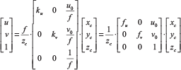
Where u,v represents the coordinates of the target point within the image plane, and where xc, yc, zc are the world coordinates of an object. Here, they are also considered as a point in the camera coordinate system. ku, kv are the scale factors along the axes of the pixel coordinates, which are defined as adjacent pixels' physical distance ratios of horizontally and vertically respectively in optical images. Moreover, uo, vo are the coordinates of the image centre in pixels, with f denoting the focal length. The orthonormal rotation matrix [ω] = f(θ1,θ2,θ3) and translation vector [
So, substituting formula (2) into formula (1), the laser-depth coordinates are transformed into the optical image coordinates, such that (3) is acquired:

According to Eq. (3), the world coordinates of the object are denoted by zc = w31 xt + w32yt + w33yt + w33zt + t3, so the points of the laser rangefinder mapping onto optical images are completed successfully.
3.2 Grey-scale interpolation
Since the coordinates of each pixel are discrete, it may fall on the non-integer pixel after the coordinate transformation. The interpolation method is needed to use after each coordinate transformation in order to fall on the exact pixel points. Hence, we use the neighbour interpolation method to realize grey-scale interpolation, as is depicted in Figure 2.

Flowchart of near interpolation method
Here, the four surrounding points are calculated while the coordinates are not integers, firstly, four pixels' coordinates surrounding the laser rangefinder mapping point after the spatial coordinate transformation are obtained. Secondly, the distance between the laser's mapping point and its four surrounding pixels is computed. Thirdly, the original laser rangefinder point coordinate is substituted by the minimum distance mapping pixel point coordinate.
4. The Calibration Pattern of the Camera's Intrinsic Parameters
The camera parameters are classified into intrinsic parameters and the extrinsic parameters. Generally, the camera's inherent characteristics and properties are determined by its intrinsic parameters, since they do not change relative to the pose and orientation of the camera. Furthermore, for a camera, if the focal length or the mechanical structures maintain invariability, its intrinsic parameters will remain fixed. However, the extrinsic parameters represent the pose and orientation information of the camera in the world coordinate system. Therefore, the extrinsic parameters can be denoted by the orthonormal rotation matrix and translation vector. As such, it is necessary to measure the intrinsic parameters and extrinsic parameters of the camera, especially the position and orientation of the target objects that are restored from the optical image to the spatial coordinate. This process is called ‘camera calibration’. Thus, the intrinsic and extrinsic parameters of the camera are indispensable to data fusion.[17]
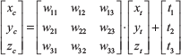
From Figure 3, (Xc,Yc,Zc) are the coordinates of Pc on the scene plane in the world system, the line between Pc and the camera interact with the optical plane on PA, which is an image ideal point, and its coordinate is called (XA,YA,fA). Meanwhile, (XD,YD,ZD) are the coordinates of an actual image point PD mapping PA in the camera image plane. The rotation matrix RD and the displacement translation vector TD are used to describe the coordinate transformation [18] as in (4):
Here,

Further, we can obtain the transformation relationship of the camera coordinate system mapping to the optical image coordinate system according to Eq. (5):


Calibration of a camera: spatial-physical model
Where MA represents the camera's intrinsic parameters matrix, which is determined by its inherent characteristics. Consequently, the relationship between the world coordinate system and the optical image coordinate system can be expressed as Eq. (7) according to Eq. (4) and Eq. (6):

Here,
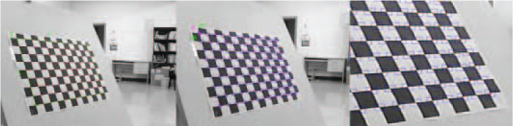
4.1 Calibration Checkerboard
The camera calibration board uses a planar checkerboard, as shown in Figure 4 (its grid side is 30mm).

Camera calibration board
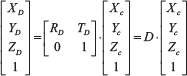
4.2 Select Calibration Images
Multiple angle samplings are adopted by the camera calibration. Here, it is unnecessary to fix the positions and orientations for the camera's intrinsic parameters' calibration. Thus, we obtain lots of sampling data, as in Figure 5.

Samplings of the calibration board
4.3 Corner Search
In a clockwise direction, starting from the top left corner, the initial values of each corner point are set through the ratio of the selection box, as shown in Figure 6. Additionally, the side length of each small grid should be given before the calculation (e.g., 30mm). The system supposes the corner search range to be five pixels, and the process of the search is shown in Figure 6.
Corner search
4.4 Camera Calibration
Inputting the corner point information into Zhang's parameter calibration tools, we can acquire the intrinsic parameters of the camera. Meanwhile, the Camera Calibration Toolbox for MatLab [17] is utilized; it can also output the extrinsic parameters of the camera in the three-dimensional coordinates, as shown in Figure 7.
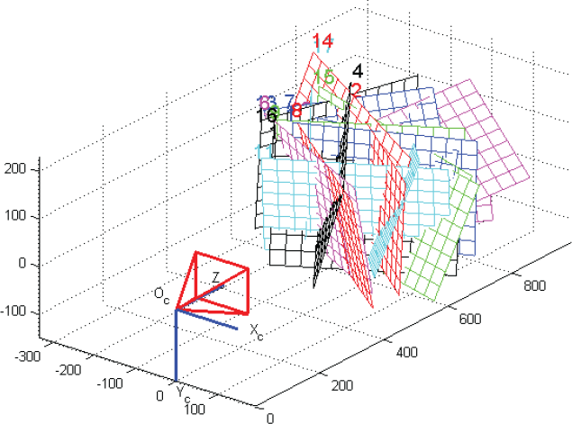
Output extrinsic parameters of the camera
4.5 Intrinsic Parameters of Camera
After calculation, we obtain the intrinsic parameters as (8):

4.6 The Errors Analysis of Camera Calibration
The parameters of the camera are substituted into Eq. (7) and then the errors of the camera calibration are analysed by the “Camera Calibration Toolbox for MatLab”. The output errors' distributions of the above camera calibration process are shown in Figure 8, with the different colours corresponding to different groups of the corner sets.

The error distributions of the camera calibration
The calibration of a camera is also considered to be an optimization problem, which is regarded as minimizing the distance between the features from the camera's measured objects and their actual position. After calibration, since for any point of the world coordinate system we can connect it with the optical centre by a straight line, then this line will intersect with the optical plane. Therefore, its precise coordinates on the optical image can be located by this intersection point. The above is significant and crucial for the data fusion of the laser rangefinder and camera, which affects the fusion precision and efficiency closely.
5. Calibration of the Laser Rangefinder and Camera for Data Fusion
5.1 Intrinsic and Extrinsic Parameters' Separated Estimation
Before the parameters' analysis, the coordinate transform formula (9) is gained according to (3):

Here, the laser rangefinder data are expressed in polar coordinates. As for the fusion platform, a camera is fixed to the top of the laser rangefinder, the laser rangefinder the Cartesian coordinates of a point are as in (10):

Here,
t
ρ is the measure distance of the laser rangefinder and θ is its scan angle. As such, the rotation matrix [
We can define the coordinate transform formula Eq. (9) in the form of Eq. (11):

In Eq. (11),

Here, A and B are the characteristic line parameters. However, the form of the traditional parameters' estimation considers intrinsic and extrinsic parameters as mixed parameters, which ignores the intrinsic relevance among them. Therefore, the intrinsic and extrinsic parameters of camera are mixed for estimation, as (13) is given according Eqs. (11) and (12):

The intrinsic and extrinsic parameters separate estimation is proposed in this paper, which considers all the camera's intrinsic and extrinsic parameters, and divides them to be dealt with. Furthermore, the separated estimation equation of the camera's intrinsic and extrinsic parameters is acquired as (14) according Eqs. (9) and (12):

According to Eq. (13), the nine undetermined parameters of a0,b0,c0,a1,b1,c1,a2,b2,c3 are calculated for the mixed estimation of the intrinsic and extrinsic parameters. Whereas the separated estimation of the intrinsic and extrinsic parameters requires to solve the 13 parameters of fu,fv,u0,v0, w11,w12,w13, w21, w22, w23, t1,t2,t3 according to Eq. (14). Here, w31= w32= w33 =0 according (10). Thus, the mixed parameters are simpler than the separated estimation for the estimation number of the undetermined parameters, because the mixed estimation method of intrinsic and extrinsic parameters ignores the interrelation among the parameters. In fact, (ai,bi,ci) are almost dependent parameters. For instance, c0 = fut1 + u0 t3 and c3=t3, so c0 can also represent fut1 + u0c3. Therefore, the parameters are not mutually independent. If a mutual relationship among these parameters is neglected, this will give rise to error increases. Meanwhile, for a certain range of parameters' optimization, selecting their initial values is relatively challenging, which may bring about an inability to converge or obtain an optimal solution. Thus, we choose the separated estimation method of intrinsic and extrinsic parameters.
5.2 The Characteristic Parameters' (A,B,xt,yt) Identification
Since the relative position-orientation of the laser rangefinder and camera in the space coordinate system is unchangeable, the intrinsic parameter matrix (fu,fv, u0, v0) of the camera can be calibrated as all known variables. Thus, only the rotation matrix [
Moreover, lots of experimental data are needed to substitute into formula (14) so as to complete the solving and estimating of the other parameters. These various experimental data are obtained by altering the relative pose between the objects and the camera under different experimental surroundings. For instance, by changing the inclination of the object, or by adjusting the distance between the object and the camera. Significantly, it must be guaranteed that the laser rangefinder and optical image data are collected synchronously, so at least 15 groups of effective data are needed to build the equations for the other parameters' estimation and solution.
5.3 The Optimization of the Calibration Parameters for Data Fusion
5.3.1 Initial Value
Gaussian elimination (also known as ‘row reduction’) is an algorithm for solving systems of linear equations. It is usually understood as a sequence of operations performed on an associated matrix of coefficients. This method can also be used to find the rank of a matrix, to calculate the determinant of a matrix, and to calculate the inverse of an invertible square matrix. In this paper, Gaussian elimination is utilized to choose proper initial values before the sub-optimization parameters. Its benefit to the optimization algorithm is to improve the parameters' optimization performance, because the algorithm can search for the optimization solution within a certain range of initial values. For the homogeneous linear equations of Gaussian elimination, solutions are non-zero if, and only if, the determinants are equal to zero. However, the error and noise of measurement obstructs the coefficient matrix in meeting this requirement. We add a random noise

The initial values of the optimized parameters are obtained via singular value decomposition (SVD), and so the parameters' matrix
We then take this parameters' matrix
5.3.2 The Parameters' Optimization
The non-linear least square and non-linear Gauss-Newton methods are utilized to optimize intrinsic and extrinsic parameters with certain constraints. In this paper, there are two constraints: one is a minimized sum of squared error, as shown in (16), where ε = Au + Bv −1:

The other is the minimized sum of distances from points to lines, and (17) is the other constraint:

Here:


Firstly, the initial values of
The parameters' matrix
Hence, the generated result
6. Data Fusion Experiment Analysis of the Laser Rangefinder and Camera
6.1 Data Import of Heterogeneous Sensors
6.1.1 Data Import of the Laser Rangefinder Text File
Since the data imported by the laser rangefinder are a sequence of distance values, the distance value sequence is reverted to the scanning plane of the laser rangefinder. Therefore, it is more intuitive in selecting the appropriate coordinate origin for the characteristic points' extraction and analysis. Additionally, assuming that the laser rangefinder coordinate is the origin point and setting the scanning plane as the coordinate system, we can obtain the planar graph through the coordinate's restoration, as is shown in Figure 9(b).

Import data
6.1.2 Data Import of the Camera Picture File
The resolution of the image is 640 × 320, saved as a 640×320×3 array, with each pixel point saved as three-channel values. Meanwhile, each channel is represented by 8-bit data, which means that each pixel is indicated by a 24-bit colour value. Here, the point in the upper left corner is defined as the coordinate origin of the image, as is shown in Figure 9(a).
6.2 Extraction of the Characteristic Parameters A, B of Au+Bv=1
According to the characteristic line Au+Bv=1 of the camera images - which is the intersection line of two calibration boards shown in Figure 10 - the characteristic line is able to be extracted by selecting any two points manually that are not coincident points on the image. In addition, those two points can determine the characteristic line. Finally, the characteristic parameters of A,B can be calculated.
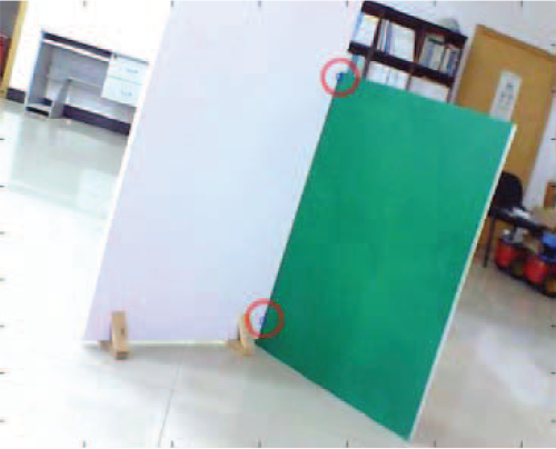
Extraction of feature line
6.3 Feature Point Pt (xt,yt)'s Extraction for the Laser Rangefinder
Before extracting feature point Pt(xt,yt), the observational data in the intersection line of the laser rangefinder scanning plane and calibration plate first need to be collected. Moreover, the laser rangefinder data of the calibration board should be displayed as an ‘arrow’ pattern, since the pattern can be set manually. Furthermore, the two edges of the straight lines of the arrow-shaped pattern are extracted, and then the intersection of the two straight lines can be calculated to obtain Pt(xt,yt). As is shown in Figure 11, the two-line intersection is the object feature point Pt(xt,yt).
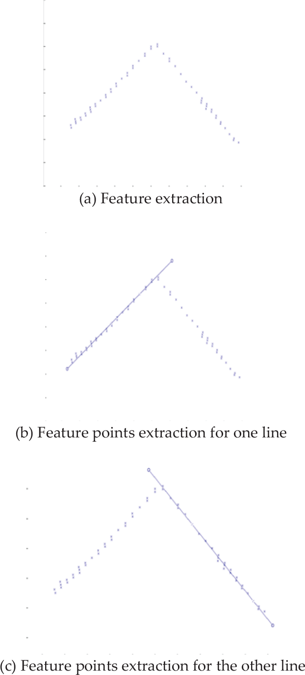
Feature extraction of the laser rangefinder
6.4 Comparison of the Performance of the Mixed and Separated Methods for Intrinsic and Extrinsic Parameters
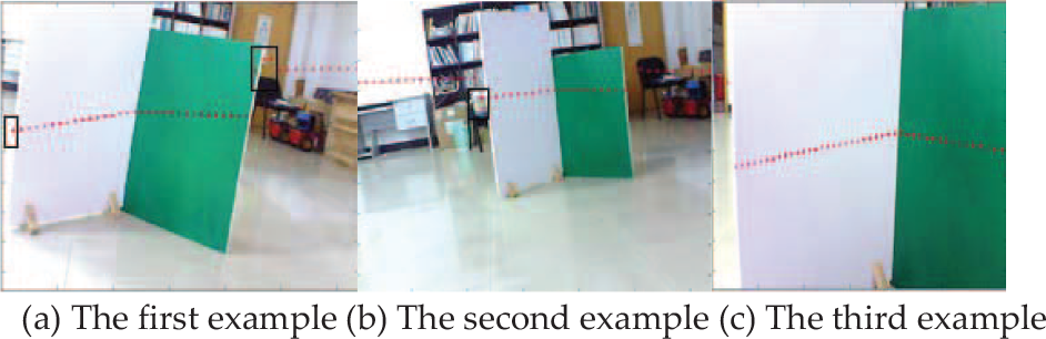
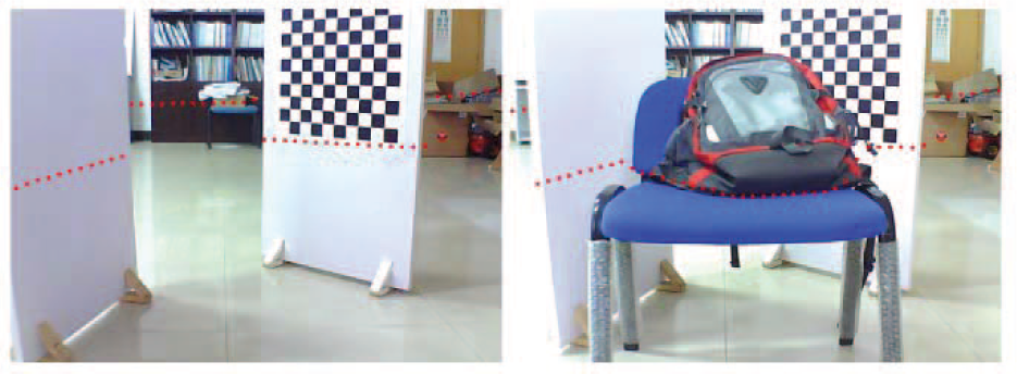
The mixed method and the separated method for intrinsic and extrinsic parameters are compared for the laser rangefinder and camera data fusion. Figure 12 shows three examples of the mixed method for intrinsic and extrinsic parameters, in which appear the apparent deviation errors in the black panes. However, the parameters' separated method leads to fewer errors, as shown in Figure 13. Meanwhile, the performances of laser rangefinder points onto the image are more similar with actual situation, according to Figure 13.
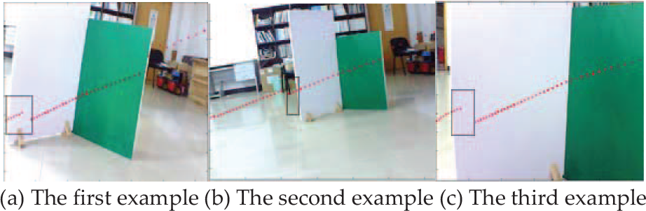
Performance of mixed intrinsic and extrinsic parameters fusion method
Performance of the separated intrinsic and extrinsic parameters' fusion method
Consequently, the performance of the parameters' separated method for data fusion works more effectively according to Figure 14, and the sum of the squared error - as shown in (16) - is selected for comparing the performance of the separated parameters' fusion method with the mixed parameters' fusion method, as the sum of the squared error can represent the errors between the estimative value and the real value of the rotation matrix and translation vector.
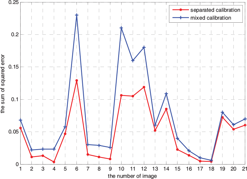
Comparison of the separated parameters' and mixed parameters' fusion methods
6.5 Synchronized Collection and Heterogeneous Data Fusion
The robotic data fusion depends mostly on the accuracy of the calibration parameters and the data's synchronized collection. If synchronized collection falls outside a certain time range, it will also lead to the fusion data being completely invalidated. Similarly, if the calibration parameters' errors are larger, this will result in the failure of data fusion.
6.5.1 Synchronized Data Collection
This system mainly employs timers and multi-threaded data buffers. The implementation process involves the following steps: (1) Establish a single thread for laser rangefinder data sampling and put the laser rangefinder data into a buffer; (2) Establish a separate thread for camera image capturing and also put the camera image data into another buffer; (3) Set a timer with a 100 ms timing cycle; (4) When the timing cycle overflows, the program the acquired data of two buffers and then mark them with a time stamp; (5) Process the data; (6) Return to Step 3.
6.5.2 Heterogeneous Data Fusion
After the parameters' optimization and synchronized data collection, the data fusion results can be displayed in the video output window, as shown in Figure 15.
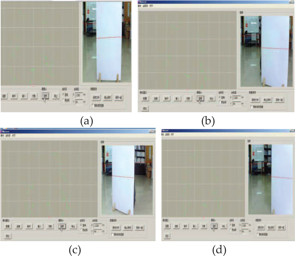
Real-time fusion results for some video scenes
Example of real-time fusion results
The pseudo-code of the data fusion
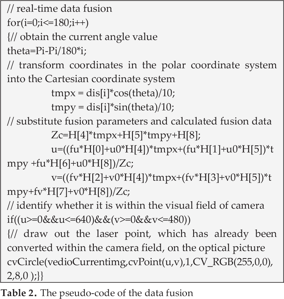
Other synchronized data fusion results are shown in Figure 16. Meanwhile the pseudo-code is as follows in Table 2.
6.6 Real-time Analysis of the Fusion Experiment
When the fusion parameters are precise enough, the performance of real time is another key factor of the information fusion for a heterogeneous sensor system, it is directly related to whether the fusion algorithm can be applied to the mobile robot platform. As is shown in Table 3, the real-time performance of the fusion algorithm is tested, and the statistics of running cycles include the data collection time, the fusion algorithm time and the display time (ms).
The average of running cycle is 109.35ms ta = 109.35ms, and its variance is S2 = 0.2394. The average time of data collection, fusion and display is only tc = ta - tT = 109.35 – 100 =9.35ms, where
Statistics of the running cycles for real-time analysis (ms)


Cycles distribution
7. Conclusion and Prospects
We have proposed a method for calibrating a heterogeneous multi-sensor system composed of a camera and a laser rangefinder. Zhang's algorithm is adopted to calibrate the camera's intrinsic parameters, and then the inherent properties of the camera are analysed. Moreover, the intrinsic and extrinsic parameters' separated calibration is proposed for accurate fusion. Meanwhile, we design an experimental method to obtain the extrinsic parameters' estimation by two intersecting calibration boards with a certain angles. Furthermore, we apply the non-linear least squares and Gauss-Newton methods to optimize the calibration parameters for different constraints. Lastly, the reliability of information fusion is ensured by the calibration parameters' being separated.
In order to take full advantage of the laser rangefinder and camera information, there should be further steps to explore the characteristics of data fusion. For example, due to the vibration of the moving mobile robot, the slight flexibility of the sensors, and other factors, the relative pose between the laser rangefinder and the camera are often prone to minor changes, which decreases the accuracy and stability of the system. Therefore, we can add the dynamic adjustment of fusion parameters to ameliorate the system. In summary, the proposed calibration method for data fusion in the paper is an improvement on the traditional mixed fusion of intrinsic and extrinsic parameters. The experimental results and analysis indicate that the proposed calibration method can ensure the real-time nature and reliability of the multi-sensor information fusion.
Footnotes
31. Acknowledgements
This paper was supported by the National Natural Science Foundation of China (61304253, 61104014), the Natural Science Foundation of Hunan (13JJ4018, 13JJ4093), the Fundamental Research Funds for the Central Universities (2012QNZT060), and the Youth Foundation of Education Bureau of Hunan province (11B070).