
Abstract
A safe interaction is crucial in wearable robotics in general, while in assistive and rehabilitation applications, robots may also be required to minimally perturb physiological movements, ideally acting as perfectly transparent machines. The actuation system plays a central role because the expected performance, in terms of torque, speed and control bandwidth, must not be achieved at the expense of lightness and compactness. Actuators embedding compliant elements, such as series elastic actuators, can be designed to meet the above-mentioned requirements in terms of high energy storing capacity and stability of torque control. A number of series elastic actuators have been proposed over the past 20 years in order to accommodate the needs arising from specific applications. This paper presents a novel series elastic actuator intended for the actuation system of a lower limb wearable robot, recently developed in our lab. The actuator is able to deliver 300 W and has a novel architecture making its centre of mass not co-located with its axis of rotation, for an easier integration into the robotic structure. A custom-made torsion spring with a stiffness of 272.25 N·m·rad–1 is directly connected to the load. The delivered torque is calculated from the measurement of the spring deflection, through two absolute encoders. Testing on torque measurement accuracy and torque/stiffness control are reported.
1. Introduction
In the development of robots intended as aids for daily living activities or as rehabilitation tools, the design factors enabling the adoption of effective interaction control schemes deserve great attention [1]. Moreover, the design of wearable robots (WRs) exhibiting a low perceived mechanical impedance can minimize the perturbations to physiological movements, as possibly needed in assistance and rehabilitation applications.
The authors have developed a lower limb WR for gait assistance and rehabilitation of hip and knee flexion/extension [2–4]. The kinematic structure of the robot is non-anthropomorphic in order to enhance the biomechanical compatibility with the human component. Macro- and micro-misalignments [5], which could cause discomfort or even pain [6, 7], are mechanically compensated, thus limiting the application to the human body of unwanted interaction forces, without resorting to control strategies based on specific sensors [8]. Furthermore, the elimination of the alignment problem between robotic and human joints improves the ergonomics of the system and eases the wearing procedure. From a design point of view, the relaxation of the anthropomorphism constraint significantly extends the field of possible technical solutions, which can be evaluated taking into account the dynamic properties (e.g., in terms of robot inertia and actuation torques) of the resulting system. For instance, the increased design freedom allows the optimization of robot dynamical properties and to properly place the actuators, e.g., close to the trunk, for reducing the inertial effects associated to their oscillations during walking and the resulting inertia perceived by the user. Conversely, if the actuators are not co-located with the human joints, the required torque profiles should be calculated taking into account the desired assistance level and the kinematic advantages/disadvantages of the robotic kinematic chain. It is therefore evident that if the kinematic design space is enlarged beyond the usual anthropomorphic solution, the problem of selecting one specific kinematic architecture is strictly interwoven with the problem of developing a suitable and specific actuation system. The actuation apparatus represents one of the most important “technological bottlenecks” in the design of robots for lower limb assistance, where the challenge is to simultaneously match power, accuracy and safety requirements [9]. To this end, compliant elements can be beneficial for the development of actuators with low intrinsic output impedance (high kinematic efficiency, low friction and reflected inertia). With regards to the specific WR developed by the authors, its kinematic structure, shown in Fig. 1, has been selected starting from a systematic exploration of the properties of the admissible topologies, as detailed in [2]. The optimized robotic structure and the related actuator torque profiles are shown in Fig. 1.
In particular, actuator torque and power requirements are derived considering data related to the normal walking of a 80 kg subject [9]. The required peak torques are 54 N·m for actuator 1 (solid black line in Fig. 1) and 46 N·m for actuator 2 (dashed black line in Fig. 1), while the RMS torques are about 29 N·m for actuator 1 and 18 N·m for actuator 2. The peak power values are 106 W (actuator 1) and 152 W (actuator 2). Since 90% of the power spectral density of torques exerted by lower limb joints is in the frequency range 0–4 Hz [9], a minimum torque control bandwidth of 4 Hz is desired.
Series Elastic Actuators (SEA) include an elastic element, e.g., a torsion spring, placed between the gearmotor and the load (Fig. 2). Passive compliance improves tolerance to mechanical shocks (e.g., resulting from foot-ground impacts) and facilitates control-based disturbances rejection [10].

(Top) Structure of the robot. M1 and M2 are the two actuators placed close to the trunk. (Bottom) Hip/knee torque profiles retrieved from the gait data-set [9] adapted to a subject's mass of 80 kg and torque required to the actuators.

General torque control scheme for a rotary SEA. τd represents the desired torque, ks the spring stiffness, Δθ the spring deflection, τ the output torque and θ the output angle.
Series elasticity also protects the motor and the gearbox in the case of unwanted collisions on the output links, and it can be used to increase actuator peak torque and power, if proper stiffness is selected according to the target task [11, 12]. The elastic component can be also used as a torque transducer, provided that its deflection is measured and its torque-angle characteristic is known. From a control point of view, the typical approach in physical human-robot interaction consists of implementing impedance or stiffness control laws based on low-level torque regulation [13]. Physical compliance allows increasing the gains of the torque controller still preserving stability margins [10]. On the other hand, high compliance lowers the controllable bandwidth, because of the saturation effects of motor speed and acceleration. This limitation can be overcome at the cost of an increased design complexity [14, 15].
In the pioneering studies on SEAs, linear prototypes were developed to be employed in bipedal walking and running robots [16]. Subsequently several rotary systems have also been proposed. Some implementations use compact frameless brushless DC motors in combination with Harmonic Drive (HD) gears, with different approaches for the inclusion of springs [17–21]. In [17], a SEA for a prosthetic elbow is developed with the torsion spring passed back through the central hole of the actuator. A similar approach is proposed in [18], with the HD used in differential mode: in this device the motor and the spring are functionally connected in series but topologically they are connected to the two input shafts of the differential mechanism (Differential Elastic Actuator, DEA). In [19], a prototype intended for a humanoid robot is presented; its compliant element is composed of a three-spoke shaft with six linear springs. In [21], a compact SEA with a flat DC motor, a HD and a custom lamellar spring, designed according to the method proposed in [22], is used to actuate an active knee orthosis. In the lower limb rehabilitation robot LOPES [23], SEAs are implemented using brushless DC motors, connected to the actuated joints through Bowden cables. Series elasticity is provided by linear springs arranged in agonistic/antagonistic configuration. The systems described in [24–26] use DC motors and planetary gears. In [24], a compliant mechanism with four linear springs is included, similar to the one in [19, 27]. In [25], a capstan drive is used and compliance is obtained by means of a leaf spring mechanism. The actuator in [26] comprises a simple commercial torsion spring. In [28], a SEA for an assistive active knee orthosis is designed. A torsion spring is mounted between a planetary gear and a worm gear. In this case the placement of a gear between the spring and the load may degrade the accuracy of torque estimation.
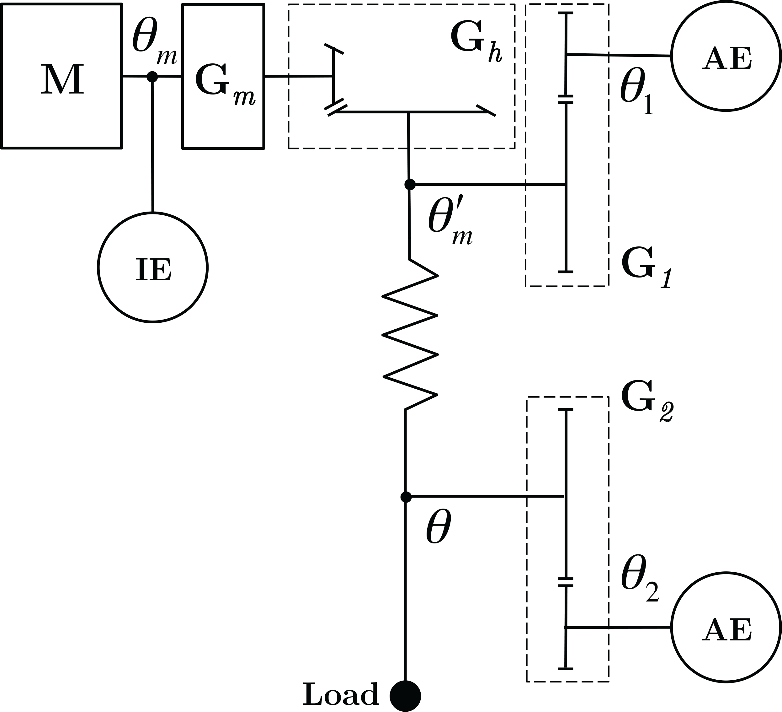
Schematic of the SEA architecture. M: motor; IE: incremental encoder measuring motor shaft rotation θm; Gm: motor reduction gear; Gh: hypoid reduction gear; G1 and G2 spur gears; AE: absolute encoders. Angles θ1 and θ2 are directly measured, and the corresponding angles θm' and θ on the input and the output shafts of the spring pack are calculated taking into account the multiplication ratio of the spur gears through a linear relation.
The described SEAs do not match the requirements of the non-anthropomorphic lower limb WR described above. In particular, the actuators described in [17–19, 21, 24–26] do not match the power/torque requirements; the cylindrical form factor of the systems described in [20, 23] does not allow the integration in the WR; in [28], the spring is not directly connected to the load thus causing non-linearities. In this paper we present a novel high-power rotary SEA overcoming the limitations of the existing SEAs with regards to the intended application. In summary, such limitations primarily regard: i) torque and power requirements; ii) encumbrance and integrability in the target WR; iii) direct connection of the spring to the load; iv) capability of accurate torque control; v) kinematic efficiency to assure the system backdrivability. This paper is structured as follows. Design choices are described in Section 2. Actuator control and experimental characterization are reported in Sections 3 and 4, respectively. Section 5 is dedicated to a discussion and conclusions.
2. Design
The developed rotary SEA has been conceived in order to displace its centre of mass apart from human joint axis, thus reducing the encumbrance in the coronal plane. A kinematic scheme of the actuator architecture is reported in Fig. 3.
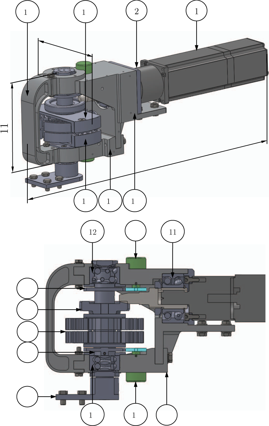
3D CAD view of SEA. 1: Motor equipped with the integrated incremental encoder, 2: planetary gear, 3: absolute encoder, 4: fork-shaped frame, 5: encoder spur gear, 6: hypoid gear, 7: spring pack, 8: encoder spur gear, 9: output link, 10: absolute encoder, 11, 12, 13: double row ball bearings, 14: gear shaft, 15: output shaft, 16: main frame, 17: bottom frame, 18: C-shaped reinforcement. Dimensions: 335 mm (axial length) × 94 mm (width) × 110 mm (thickness). Total mass is 3.5 kg.
The main components (Fig. 4) are: a fork-shaped closed frame (Fig. 4-4); a 300 W brushless DC motor (Fig. 4-1) with an integrated optical incremental encoder; a planetary gear 4.3:1 (Fig. 4-2); a hypoid gear 15:1 (Fig. 4–6); a custom torsion spring pack (Fig. 4–7); two absolute encoders to measure the deflection of the spring pack (Fig. 4-3,10); two couples of 1:2 spur gears for the non co-located measurement of spring pack deflection (Fig. 4–5,8).
The two absolute encoders are put in rotation through spurs gears. This solution introduces a three-fold advantage: i) the overall thickness of the actuator is kept small; ii) the output link is free to rotate continuously (no limitation to the angular ROM); iii) the accuracy in the reading of the spring deflection (i.e., the reduction of the quantization error) is improved by a factor 2, corresponding to the multiplication ratio 1:2 of the spur gears. The overall dimensions of the actuator are: 335 mm (axial length) × 94 mm (width) × 110 mm (thickness). The actuator mass is 3.5 kg. A picture of the SEA prototype is shown in Fig. 5.
2.1. Motor, transmission and frame
A brushless DC motor (Maxon EC-4pole 45, rated power: 300 W, Fig. 4-1) with a mass of 1.130 kg, and a maximum continuous torque of 0.635 N·m has been selected. A planetary gear (Maxon GP42C), with a reduction ratio 4.3:1 and an efficiency of 90% (Fig. 4-2), directly connected to the motor, represents a first reduction stage. A second stage, consisting of a hypoid transmission (KHK Gears Co., Japan), introduces a further reduction of 15:1 (Fig. 4-3), with a rated efficiency of 85%. The overall nominal kinematic efficiency of the actuator is therefore 76.5%, which guarantees its intrinsic backdrivability and a net power of 230W.
The pinion of the hypoid transmission is coaxial to the gearmotor output shaft, and is supported by a double-row ball bearing (NSK 3204, Fig. 4–11). The pinion engages the hypoid gear, which is in turn coaxially mounted, through a P3G polygon coupling, with the “gear shaft” (Fig. 4–14) engaging the input port of the spring pack (Fig. 4–7). The spring pack is coaxially mounted on the gear shaft on one side and with the “output shaft” (Fig. 4–15) on the other side by shape interference, which assures motion transmission with negligible backlash. The gear and the output shafts are fully constrained by double-row ball bearings (NSK 3202 bearing for gear shaft, Fig. 4–12; NSK 3203 for output shaft, Fig. 4–13). Both shafts are in stainless steel (AISI 420). The output shaft is connected to the output link (Fig. 4–9).
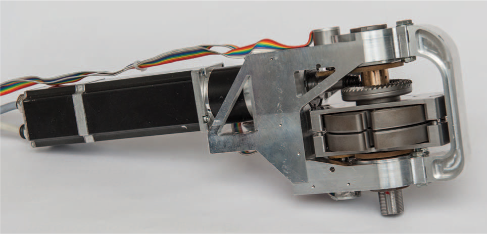
Picture of the SEA prototype.

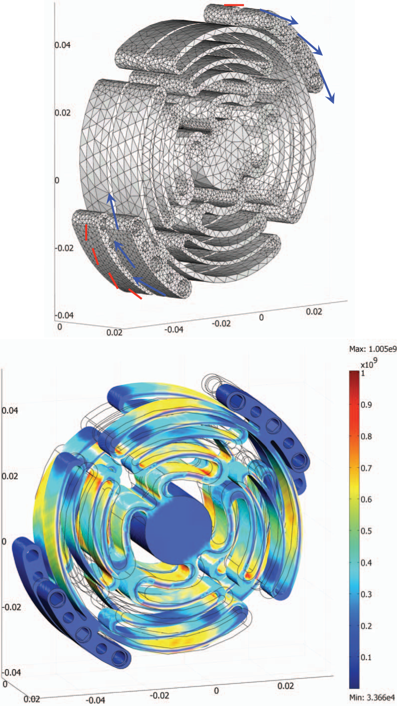
(Top) Boundary conditions, applied loads and tetrahedral mesh for FEM simulations. (Bottom) Displacement along the y-axis [mm]. Axes dimensions are [m].
The fork-shaped frame (Al 7000, Ergal), comprising the main frame, the bottom frame and the C-shaped reinforcement (Fig. 4–16, 17, 18), guarantees the overall stiffness of the structure, while providing references for the hypoid gear set. The bottom frame is connected through bolted joints to the main frame. The C-shaped reinforcement, between the main frame and the bottom frame, increases the stiffness. The design of the frame has been optimized using FEM analyses (COMSOL Multiphysics 3.5, Comsol AB) to achieve the stiffness needed to provide proper position references to the hypoid gear set. In particular, the design optimization aimed at achieving a maximum (i.e., for a torque of 60 N·m) vertical displacement less than 0.2 mm at the level of the ball bearings' housing. Such displacement is chosen as the maximum one compatible with the proper functioning of the hypoid set. The boundary conditions, the applied loads, the adopted tetrahedral mesh, and the y-axis displacement are shown in Fig. 6. The frame is fixed to the ground at the level of the four holes indicated by red lines in the figure; the applied forces (blue arrows) represent the radial and axial forces applied by the hypoid gears to the frame through the bearings. The maximum calculated displacement along the y-axis is 0.18 mm, compatible with the goal of the stiffness optimization problem.

3D view of the spring pack. Input/output connections and maximum deflection allowed by the mechanical hard stops are indicated. Dimensions of the spring pack: 90 mm (external diameter, not shown in figure) × 23.5 mm (total thickness).
2.2. Torsion spring
Based on the authors' previous work [22], a compact, monolithic, torsion spring was designed for the rotary SEA. The desirable physical stiffness of SEAs for locomotion assistance, as retrieved from a literature analysis, may range from 100 to 300 N·m·rad−1 [20, 21, 29–31]. Considering this assumption and the simulation studies reported in [32], on the basis of the velocity and current limitations of the selected DC motor, a stiffness value of 250 N·m·rad−1 was taken as a target specification for the torsion spring pack. Both the design requirements (i.e., 60 N·m peak torque; 250 N·m·rad−1 stiffness) are hardly met by a single compact elastic element. To solve this issue, a serial mounting of two identical custom torsion springs was used (Fig. 7). In this configuration, each spring has to withstand a peak torque of 60 N·m while exhibiting a torsion stiffness of 500 N·m·rad−1. Torque is transmitted between the external spring arcs acting as input and output ports, while the two internal cylinders of the springs are connected together (Fig. 7). Mechanical hard stops, mounted in parallel to the springs, prevent their over-deflection.
In order to minimize spring weight and dimensions, a monolithic disc-shaped design has been investigated. This shape implies that the transfer of the torque between the outer and the inner parts of the spring occurs through flexible elements. The shape and dimensions of such flexible elements are defined through an iterative FEM simulation-based design and optimization process, as described in [22]. Considering the stiffness and the torque requirements in safe conditions (safety factor ≥ 2), the target storable elastic energy is 7.5 J, above the maximum value of the spring described in [22]. To increase the level of storable elastic energy, a novel topology was investigated, which includes a symmetric structure with a radial replication of four elastic elements (worm-shaped lamellae). Figure 8 shows an arbitrary morphology based on the selected topology. Let's consider a single lamellar block (Fig. 8). The distance of the m lamellae (width: sj, j = 1, …, m) from the centre is Rj (j = 1, …, m). The width of the interconnections between lamellae is wj (j = 1, …, m – 1), while the width of the interconnections between lamellae and internal cylinder/external arcs is pj (j = 1, 2). The aperture angle of the lamellae blocks is α.

An arbitrary morphology based on the selected topology.
Constant design parameters include the diameter of the internal cylinder (c1 = 21 mm), the outer radius (R = 45 mm), the width (c2 = 6 mm) and the aperture (c3 = 48 deg) of the external arcs and the thickness (z = 11 mm). Table 1 summarizes the design variables, with definition of lower and upper bounds for variable parameters, minimum increment adopted in the iterative optimization process and optimized values.
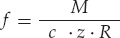
FEM analyses were performed (COMSOL Multiphysics 3.5, Comsol AB) with the external surfaces of the spring arcs fixed to the ground (red lines in Fig. 9). The external surfaces of the other spring arcs are loaded with a tangential distributed force (blue arrows in Fig. 9), equivalent to a pure torque (M):
A tetrahedral mesh, refined about lamellae and holes (higher curvature elements), is adopted (Fig. 9). A stationary non-linear solver (SPOOLES) with a relative tolerance of 10−6 is used to compute large deformations. The spring material is maraging steel 300 (Bohler W720, Young modulus: 193 GPa) selected for its high nominal yield stress (2.0 GPa) and ultimate tensile strength (2.1 GPa) after an ageing treatment of three hours at 500 °C. 1:1 spring deformation and von Mises stress under an applied torque of 60 N·m are shown in Fig. 9. The maximum von Mises stress is 1.01 GPa (safety factor: 2). The calculated arc rotation is 0.25 rad, corresponding to a torsion stiffness of 235.70 N·m·rad−1. The expected stored elastic energy is 7.64 J, while the specific energy, considering that the weight of the spring pack is 0.37 kg, is 20.58 J/kg.
The optimized spring pack, described by the design parameters in the fourth column of Table 1, was monolithically manufactured from a single metal block, thus avoiding any possible backlash issue in the shaft/hub couplings. The block was first radially grooved to create two cylindrical heads and then these two parts were machined through WEDM (Wire Electrical Discharging Machining) to obtain the internal lamellae. The spring pack is connected with the gear and output shafts through shaped flanges.
(Top) Boundary conditions, applied loads and tetrahedral mesh for FEM simulations on the elastic element. (Bottom) von Mises stress and 1:1 deformation for the maximum load. Axes dimensions are in [m].
2.3. Sensors
The sensing scheme used in the SEA is shown in Fig. 3. Motor shaft rotation (θm) is measured through an integrated Incremental Encoder (IE in Fig. 3, Maxon R35i, optical, resolution: 7.7·10−4 rad). Hall sensors are employed for commutation of motor winding current.
The estimate of the output angle (θ in Fig. 3) and, hence, of the interaction torque with the environment are provided by two Absolute Encoders (AE in Fig. 3, Gurley A19, optical, resolution: 1.9·10−4 rad). It is worth noting that the spring deflection measurement provided by these two sensors is not affected by gearmotor backlash. Moreover, absolute readings simplify the initialization procedure aimed at measuring the output position and the residual spring deflection. The Gurley A19 AEs have been selected for their good compromise between size (diameter: 19 mm; axial length: 29 mm) and resolution. Anyhow, their form factor does not allow co-axial mounting to the shaft, while keeping the total thickness low. To address this issue, precision spur gears (G1 and G2, module: 0.2) have been introduced between the shaft and the encoders. The spur gears, with a gear ratio: 1:2, introduce a 50% reduction of angular measurement quantization. The resulting quantization is 9.6·10−5 rad for both θ'm and θ. Considering the targeted torsion stiffness for the spring (250 N·m/rad), a torque quantization of 2.4·10−2 N·m is expected, as resulting from the quantized measurement of the deflection Δθ = θ'm – θ.
Search space for the optimization problem of the selected spring topology. For each parameter, the search space is defined, based on the upper and lower bound and minimum increment adopted in the optimization process. The final optimized value for each parameter is reported. Rj, sj, wj, pj are in [mm], α is in [rad].

3. Control
Torque regulation is based on the measurement of the spring deflection. Considering a linear torque-deflection relationship for the spring, the torque delivered by the actuator can be estimated as τ = ksΔθ, being ks the actual spring stiffness.
Different approaches to SEA torque control have been proposed. First solutions were based on the regulation of motor currents, with an additional feedforward compensation of motor inertia [33]. In [34], current regulation was replaced by position control. In [24], a velocity loop, nested in an external torque loop, was proposed. In this scheme the motor is considered as an ideal velocity generator; the analysis of control requirements to assure passivity was presented in [35]. In [36], differences between inner position and velocity control loops were investigated. In [37], a PD torque controller was coupled to a disturbance observer to compensate for modelling errors and plant variations. This approach has been modified in [38] where also the model of the actuator was taken into account.
The control scheme used in this paper follows a cascade approach with an inner PI velocity control loop and an outer PI torque control loop (Fig. 10) [24, 35]. A stiffness control loop generates the desired elastic torques in the form: τd = kv(θd –θ), being kv the desired virtual stiffness.
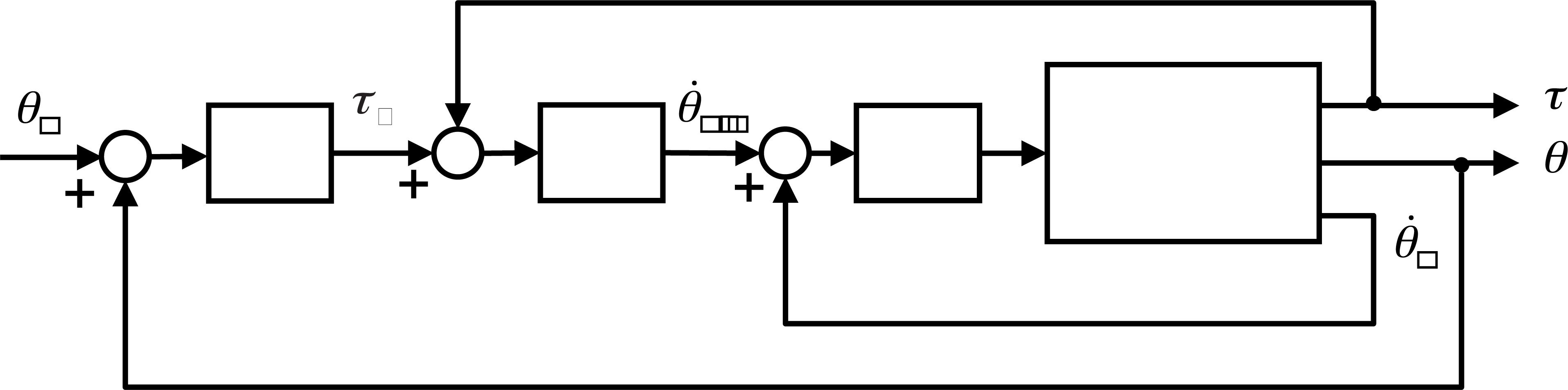
SEA control schematic. τ, θ are the output torque and angle respectively;

SEA control implementation. Velocity controller runs on the EPOS2 device while torque and stiffness controllers run on the RT level of the cRIO central control unit.
The control hardware (Fig. 11) includes: i) a Maxon EPOS2 70/10 control unit to drive the motor, capable of providing 48 V constant voltage and 10 A maximum continuous current (peak of 20 A for less than 1 s) and comprising interfaces with motor windings, Hall sensors and motor optical encoder; ii) a National Instruments (NI) compactRIO-9022 (cRIO) unit, which includes a reconfigurable Field-Programmable Gate Array (FPGA) module and an embedded controller running LabVIEW Real Time (RT) software. The device also comprises a NI 9403 high speed digital I/O and a NI 9853 high speed CAN module as interfaces with the absolute encoders and the EPOS2 driver, respectively. The FPGA module of the cRIO system is programmed to acquire absolute encoders signals (SSI communication) and to execute CAN bus low-level communication with the EPOS2 controller (transmission of motor commands and reading of data on current, position and velocity).
Torque and stiffness control loops run on the RT level (500 Hz) of the cRIO device; the torque controller generates the desired velocity commands transmitted via CANopen protocol to the velocity controller, running on the EPOS2 device (1 kHz). Feedback for torque and stiffness controllers are based on the measurement of the absolute encoders, filtered using second-order lowpass Butterworth filters, with a cut-off frequency of 40 Hz.
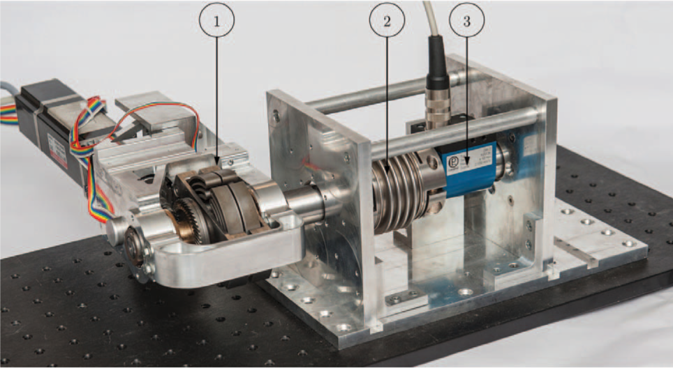
Dynamometric test-bed for the characterization of the spring stiffness. 1: SEA with the output connected to the flexible coupling; 2: flexible coupling connecting the SEA to the torque sensor; 3: torque sensor fixed to the test-bed frame.
4. Experimental tests
4.1. Torque measurement
The torque-deflection characteristic of the spring pack was obtained through a custom dynamometric test-bed (Fig. 12).
Possible inaccuracies in the measurement of absolute encoders, due to non-linearities and backlash in the spur gears (G1 and G2 in Fig. 3), were preliminarily assessed by using a calibration encoder.
An additional Gurley A19 was directly mounted onto the gear shaft to measure the angle θ'm (Fig. 3), and the motor was commanded to track position profiles with a slow, constant velocity (0.035 rad/s), reversing the direction of motion after a complete revolution of the gear shaft. During the experiments, both angles θ'm and θ1 were continuously measured at a 1 kHz sampling rate, and a linear correlation was used to estimate the error provided by a linear angle estimation, based on the direct measurement of the output angle θ1 to infer the shaft angle (θ'm). The combined effect of non-linearity and backlash provides a maximum error of 5·10−3 rad (0.3 deg), with a RMS Error of 1.7·10−3 rad (0.1 deg), for each measured angle, R2 regression coefficient of 1.0000, and a slope of 1.9998. The results of the experiment are reported in Fig. 13, showing the linear regression fit, and the corresponding residuals, obtained for a full rotation of the gear shaft.
For the spring pack characterization the SEA output shaft was connected to a torque sensor (Lorenz Messtechnik GmbH DR-2, Fig. 12-3) fixed to the test-bed frame. To avoid spurious forces deriving from radial misalignments between the SEA and the sensor shafts, a flexible coupling (Rodoflex ATMK60L77, Fig. 12-2) was interconnected. The SEA was commanded to track a deflection profile as a sequence of steps of amplitude 4.4·10−3 rad and duration 2 s. Torque delivered to produce the desired deflection was measured via the torque sensor. Experimental data and linear regression for a maximum torque of 30 N·m are reported in Fig. 14.
It is possible to observe the absence of any significant backlash (low torques region). Two linear regressions (positive and negative deflections) were performed, imposing null y-intercept. The regression coefficients differed by about 3% in the two directions. Hence a global stiffness of 272.25 N·m value was calculated as the average between tests on the two rotation verses. Based on the experimentally identified stiffness, the actual maximum stored elastic energy in the spring pack is 6.61 J when 60 N·m are applied. The torque measurement has a quantization, due to the digital measurements of the absolute encoders, of 2.6·10−2 N·m, slightly above the expected one (par. 2.3).

Accuracy of angle measurement based on precision spur gears and absolute encoders. The input angle θ'm is commanded a constant speed rotation (0.035 rad/s), reversed after a complete revolution (θ'm = 2π, ccw and cw labels). (Top) Linear regression calculated between the input angle θ1 and output angle θ'm (R2 = 1.0000, slope: 1.9998. The zoom area shows the effect of backlash in the inversion of motion, which is limited to 1.7·10−3 rad (0.1 deg). (Bottom) Residuals of the linear fit showing a maximum non-linearity error equal to 5·10−3 rad (0.3 deg), for the estimate of θ'm.

Spring pack torque-deflection characteristic. Linear regression has a correlation coefficient R2 = 0.998.
4.2. Torque control
Torque control performance (i.e., step response and closed-loop control bandwidth) of the SEA was identified with the output shaft of the actuator fixed (Locked Output, LO), so that torque regulation capability was evaluated only considering the deflection of the elastic element, without any external load disturbance. PI torque controller gains were regulated based on the system response to commanded step torques in order to have no overshoot and a rise time (actual torque spanning from 5% to 95% of the set-point) of about 50 ms. A representative response of the system to a commanded step with amplitude 10 N·m is shown in Fig. 15, demonstrating overshoot absence and a regime error of about 0.1 N·m. This torque regulation inaccuracy can be considered widely acceptable for human assistance applications.
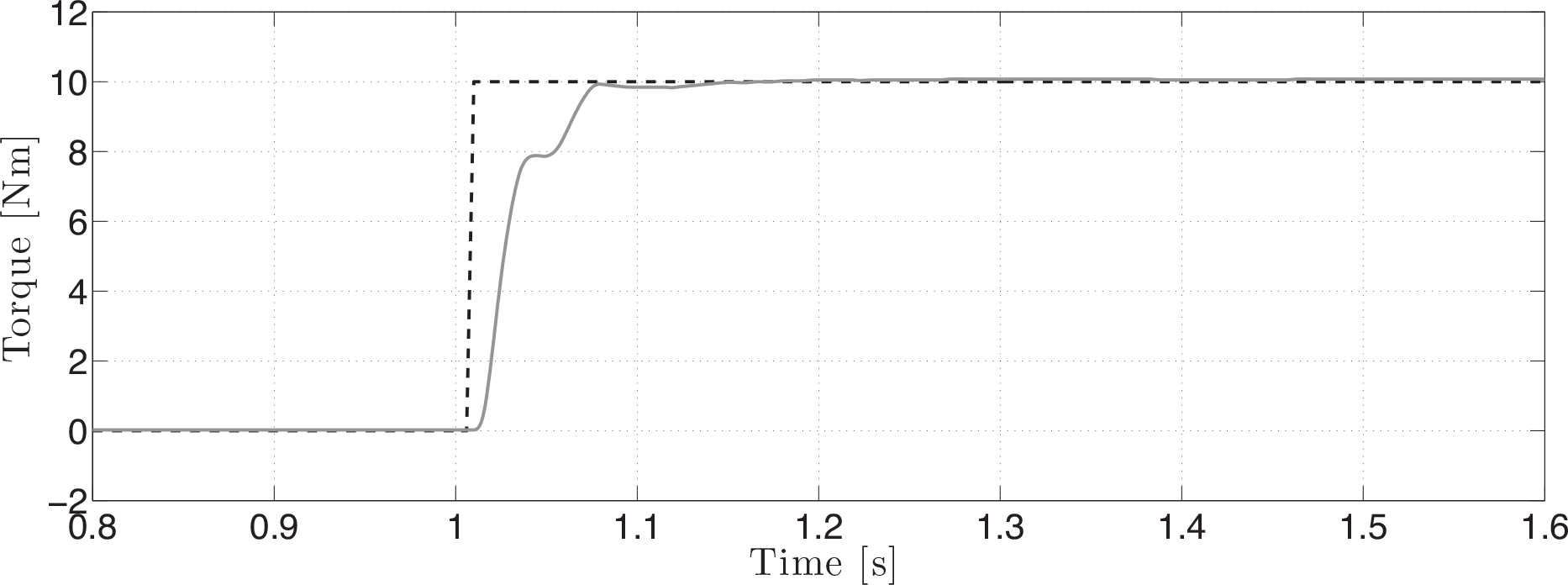
Response to a representative torque step command with amplitude 10 N·m. Dashed line: desired torque; solid line: actual torque.

Response to a Schroeder multisine desired torque profile with a peak value of 15 N·m (30 N·m peak to peak, RMS: 8.33 N·m) and frequency content of 0.1–10 Hz. Dashed line: desired torque; solid line: actual torque.
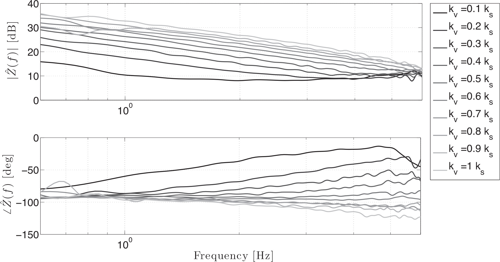
The transfer function between the desired torque τd and the actual torque τ delivered by the actuator in LO conditions in the frequency domain is:
being T(f) and Td(f) the Fourier transforms of τ and τd respectively.
To experimentally determine the transfer function Gtor(f), the SEA was commanded to track a torque profile defined as a Schroeder multisine signal [39]. A dynamic characterization experiment was conducted to determine the torque regulation performance of the developed system. A Schroeder multisine signal with a peak value of 15 N·m (RMS value of 8.33 N·m) and constant spectral power density in the range [0.1, 10] Hz (negligible power content elsewhere) was specified as the desired torque. Torque tracking performance in LO conditions is reported in Fig. 16. The transfer function Gtor(f) was estimated using non parametric system identification [40, 41] as follows:

with Pτdτ(f) representing the cross-spectral density of the input (desired) torque and the output (actual) torque, and Pτdτd(f) being the auto-spectral density of the input. The performance of the controller is shown in Fig. 17. The transfer function shows an attenuation of 3 dB at 6.5 Hz. To assess the estimation reliability, the squared coherence function was calculated as a measure (from 0 to 1) of the correlation between the input and output at each frequency:

in which Pττ is the auto-spectral density of the output. The coherence value was found to be around 0.9 in the tested frequency range.

Bode diagram of the estimated torque control transfer function Ĝtor(f). Desired signal is a Schroeder multisine (Fig. 16). The torque control bandwidth, calculated as the frequency corresponding to an attenuation of 3 dB, is 6.5 Hz.
4.3. Stiffness control
The stiffness control performance was evaluated with the actuator commanded so as to generate elastic torques with different values of the virtual stiffness kv, while keeping θd fixed. In these conditions the output shaft was manually perturbed with oscillatory movements.
Mechanical impedance is defined in the frequency domain as:

being Ω(f) the Fourier transform of

with
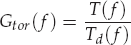
In order to assess SEA stiffness regulation capability, tests were carried out varying kv in the range [0.1 ks, ks], with step increases of 0.1 ks. The estimated transfer function (6) is reported in Fig. 18. Data are shown in the range 0.6 – 6 Hz, where the coherence between the imposed velocity and the interaction torque was found to be greater than 0.8 for all the tests. It can be seen that stiffness regulation quality increases with kv. The performance degradation in rendering a virtual stiffness (kv) much lower than that of the physical stiffness (ks) is in line with literature results [21, 29]. The phase of Ẑ(f) is slightly smaller than −90 deg for kv > 0.5 ks, hence the system becomes not passive. Anyhow, passivity represents a conservative condition for coupled stability since it allows stable interaction with any external arbitrary passive systems. In fact, the stiffness-controlled SEA remained stable in all experimental conditions involving the interaction with a human, for all values of kv ≤ ks.
Bode diagram of the estimated transfer function Ž(f) when rendering a pure elastic behaviour with different virtual stiffness values kv.
4.4. Backdrivability
Both intrinsic and active backdrivability were tested. In particular, the output link was manually perturbed in two conditions: with the motor switched off (Unpowered Mode, UM) and with a null commanded torque (Zero-torque Mode, ZM), i.e., with τd = 0. In both cases the imposed motion θ and the interaction torque τ were measured and the actuator output impedance was calculated. In particular, perceived inertia Î and viscous frictio b̂ were estimated by regressing the interaction torque with angular velocity and acceleration in the form:

This multivariable linear regression was calculated on four trials in both UM and ZM conditions. With the motor unpowered, the estimated impedance parameters, averaged over all the trials, were ÎUM = 0.1671 ± 0.0208 kg·m2 and b̂UM = 1.1746 ± 0.0571 N·m·s·rad−1. The reliability of this result is demonstrated by a mean R2 coefficient of 0.9160 and by a 8% discrepancy between the experimentally identified inertia and the value estimated from CAD and materials data. It is worth mentioning that the computed value also comprises the inertia of the aluminium output link connected to the actuator output shaft and employed to perturb it during the tests. In ZM conditions the estimated impedance parameters, averaged over the four trials, were ÎZM = 0.2536 ± 0.0009 kg·m2 and b̂ZM = 0.0958 ± 0.0038 N·m·s·rad−1. The mean R2 coefficient in this case was 0.9154. These results not only demonstrate the high intrinsic backdrivability of the system but also the possibility of further reducing perceived impedance using zero-torque control.
5. Discussion and Conclusions
This paper presents the design and the characterization of a novel rotary SEA suitable to be included in a WR for the assistance and rehabilitation of planar knee and hip movements (sagittal plane). The presented design was carried out with the aim of fulfilling a set of requirements defined on the basis of the chosen morphology of the developed active orthosis. The chosen application field poses significant challenges to the design of an actuator, in terms of amplitude, bandwidth and accuracy of torque regulation.
The problems of the encumbrance of the actuator and of the resulting increased apparent inertia are addressed with the adoption of a novel architecture where the gearmotor is placed alongside human limbs. This solution allows the non co-location of the actuator centre of mass with respect to the axis of the supported human joint, thus reducing the inertia perceived at the more proximal joint.
For example, in the hypothesis of integrating the presented actuator in a powered knee orthosis for gait assistance, the inertia of the knee actuator perceived at the hip joint is equal to 0.56 kg·m2.
Since the resulting moment of inertia in the sagittal axis of the WR structure, with respect to an axis collinear to the hip joint, can be approximated as mact · d2 (where mact is the mass of the actuator and d is the distance between the actuator centre of mass and the hip joint), the developed architecture allows the reduction the parameter d by 16%, thus resulting in a reduction of the moment of inertia by 26%. The developed solution is equivalent, from the standpoint of the intrinsic apparent inertia perceived at the hip joint, to an anthropomorphic orthosis powered by an actuator with a mass of 2.45 kg.
The custom torsion spring pack, connected to the output shaft in direct-drive configuration, minimizes transmission non-linearities and allows high-fidelity torque tracking.
One of the major novelty element of the pursued design is the monolithic torsion spring itself, which was purposively optimized and fabricated, since no commercial solution would have been able to provide the desired torque and stiffness properties with a single, compact and lightweight design.
The spring pack torque-angle characteristic was derived by correlating imposed deflections and measured torques. High linearity was found with a stiffness value differing only 15.5% from the one targeted in FEM analysis. Similar discrepancies were previously reported in other works using different FEM methods and/or different spring geometries [20, 22]. It is worth noticing that this discrepancy cannot be imputed to the series compliance of the characterization set-up. From test-bed component datasheets, it was determined that the equivalent series parasitic compliance introduced by the set-up was one order of magnitude (about 16 times) higher than the one to be measured.
Torque control performance of the developed SEA prototype was experimentally characterized based on non-parametric system identification techniques.
The estimated transfer function between a torque desired profile (flat frequency spectrum from 0.1 N·m to 10 N·m) and the actual delivered torque was found to have an attenuation of 3 dB at 6.5 Hz. Reduced regime errors in response to torque step commands (in the order of 0.1 N·m, less than 0.2% of the full scale of the actuator) were found. The achieved torque regulation bandwidth and accuracy are widely adequate for proper torque tracking in gait assistance applications.
Stiffness control was implemented and tested over a range of desired virtual stiffness values spanning 0.1–1.0 times the value of the physical elastic element. The capability of the SEA of rendering the desired pure elasticity was tested by manually perturbing the actuator output shaft and by evaluating the transfer function between the imposed velocity and the actuator delivered torque. The desired stiffness was correctly displayed for all the frequencies of the manual stimulations (up to about 6 Hz). A degradation of control capability for stiffness values far below that of the physical spring was found, in agreement to similar studies [21, 29]. Despite passivity being lost for high virtual stiffness values, no stability issues were experienced in any interaction tests.
Actuator transparency was evaluated by identifying output inertia and viscous friction when the actuator was switched off (UM condition) and when it was commanded with a null torque set-point (ZM condition).
The actuator was found to be intrinsically backdrivable and zero-torque control was able to further reduce the viscous friction by one order of magnitude (from 1.1746 N·m·s·rad−1 to 0.0958 N·m·s·rad−1), still allowing stability. It is worth noticing that the perceived inertia in ZM condition slightly increased due to the selected velocity-source control approach. Indeed, starting from the results in [35], it can be demonstrated that impedance transfer function of the closed-loop system, when a nulltorque is demanded, is:

with

which shows that the system reduces to a pure inertia, whose value is inversely proportional to the torque control integral gain. It thus appears clear that the value of Kt i should be selected after considering the trade-off between the contrasting requirements of improving accuracy of torque control and of minimizing apparent inertia and viscous friction in zero-torque control mode.
Four replications of the presented SEA are now successfully integrated in a lower limb non-anthropomorphic WR for gait rehabilitation recently developed by the authors [4]. The current version of the robot is treadmill-based and wired to remote power supply units. In the development of an assistive (autonomous) version of the WR, the design of the actuators should take into account the residual motor capabilities of the target users. This will expectedly lower power requirements, thus limiting the portability issues associated to the use of battery packs.
Footnotes
13. Acknowledgement
This work was partially supported by the FP7 FET Proactive Initiative “Embodied Intelligence” of the European Commission, project no. ICT-2007.8.5-231451 - EVRYON (EVolving morphologies for human-Robot sYmbiotic interactiON). The authors are greatly thankful to Mr. Simone Galzerano and to Mr. Michelangelo Di Palo for their contribution on the fabrication of the device.