
Abstract
Understanding the radio signal transmission characteristics in the environment where the telerobotic application is sought is a key part of achieving a reliable wireless communication link between a telerobot and a control station. In this paper, wireless communication requirements and a case study of a typical telerobotic application in an underground facility at CERN are presented. Then, the theoretical and experimental characteristics of radio propagation are investigated with respect to time, distance, location and surrounding objects. Based on analysis of the experimental findings, we show how a commercial wireless system, such as Wi-Fi, can be made suitable for a case study application at CERN.
Keywords
1. Introduction
CERN (European Organization for Nuclear Research) and other similar scientific facilities have a need for remotely operated vehicles (mobile robots) to carry out remote inspections and radiation surveys in different areas, e.g., the Large Hadron Collider (LHC), to avoid or minimize the need for personnel to go inside the radiation areas and perform these tasks. Another similar situation is the use of help, search and rescue robots during disaster conditions [1] where humans cannot enter dangerous or harmful environments.
As the operations in hostile or radioactive environments are difficult to fully automate, the robots are equipped with teleoperation capabilities and some autonomy (intelligence) features may be added to ease the operator overload [2]. For these applications, the main wireless communication challenges to be considered are that the robot should be able to travel long distances in hostile or tunnel-like environments, and should be able to quickly transmit large amounts of data. Having a reliable communication link with the robot is essential to avoid the need for personnel access to recover the robot in the event of communication failure [3].
Using umbilical cables rather than a wireless system for the communication has some drawbacks. For instance, the Quince robot [1], which used an umbilical for communicating with the operator, became immobilized because of a communication failure on the third floor on its way back out after measuring radiation levels in the Fukushima nuclear reactor building [4].
Wireless communication avoids the cable disconnection problem typical of wired communication, which occurs when a cable is broken as a result of physical damage during operation. Therefore, wireless communication is preferable for remotely operating mobile robots in such environments.
However, underground tunnels are generally very challenging environments for radio communications [5, 6]. It is observed in [5] that the behaviour of radio signals is very different in underground mines compared to that in outdoor and Line of Sight (LOS) environments. In addition, the first step in increasing a wireless network performance is understanding the environment. Hence, there is a need to investigate how radio signals behave in scientific facilities such as at CERN, so as to properly design the wireless communication system and ensure reliability.
The contributions of this paper are two-fold:
Description of major wireless communication link requirements for typical telerobotic applications at CERN.
Experimental results giving temporal, spatial and environmental characteristics of radio signal propagation in an underground scientific facility.
The organization of the paper is as follows:
First, the wireless network requirements for typical telerobotic applications related to CERN is presented and a case study application is considered.
Then, current available wireless systems are compared and a specific wireless technology is selected for the case study application described in section 2.2.
Following some theoretical background on radio signal propagation, the scope of the experiments to be conducted is defined.
Then, during the experimental testbed, measurement parameters are described and signal propagation characteristics are analysed.
Lastly, the results of the experimental tests are discussed in relation to commercially available wireless technology (Wi-Fi).
2. Wireless communication requirements
2.1. Wireless link requirements for telerobotic applications
According to the systems engineering approach [7], the user needs are studied first before identifying a solution. Therefore, the first goal is to obtain the requirements of the wireless communication system for various possible applications at CERN from the people who need these applications. Each application has different requirements for establishing a point-to-point wireless network between the telerobot and the teleoperator. The three main parameters which define these requirements are:
Maximum admissible system latency (in milliseconds),
Minimum data transfer rate (in Megabits/second),
Maximum distance to be covered (in metres).
The system latency is a critical parameter in a real-time application. It is the amount of time taken by a data packet to travel from a source to a destination (host processing latency + network latency). It depends on the number of buffers between communication ends [8]. Network topology and coverage distance requirements (which are relevant to latency) are decided by the type of the application. Hence, these values were obtained by interviewing people requiring such applications.

ISOLDE experimental facility at CERN
The data transfer rate is defined as the speed with which the data can be transmitted and is decided by the amount of data to be transmitted. For video transmission, one can refer to [9] to find a relation between the quality of the video and the data-rate required. It is recommended that at least two live video transmissions are necessary for a vision system used for remote handling [10].
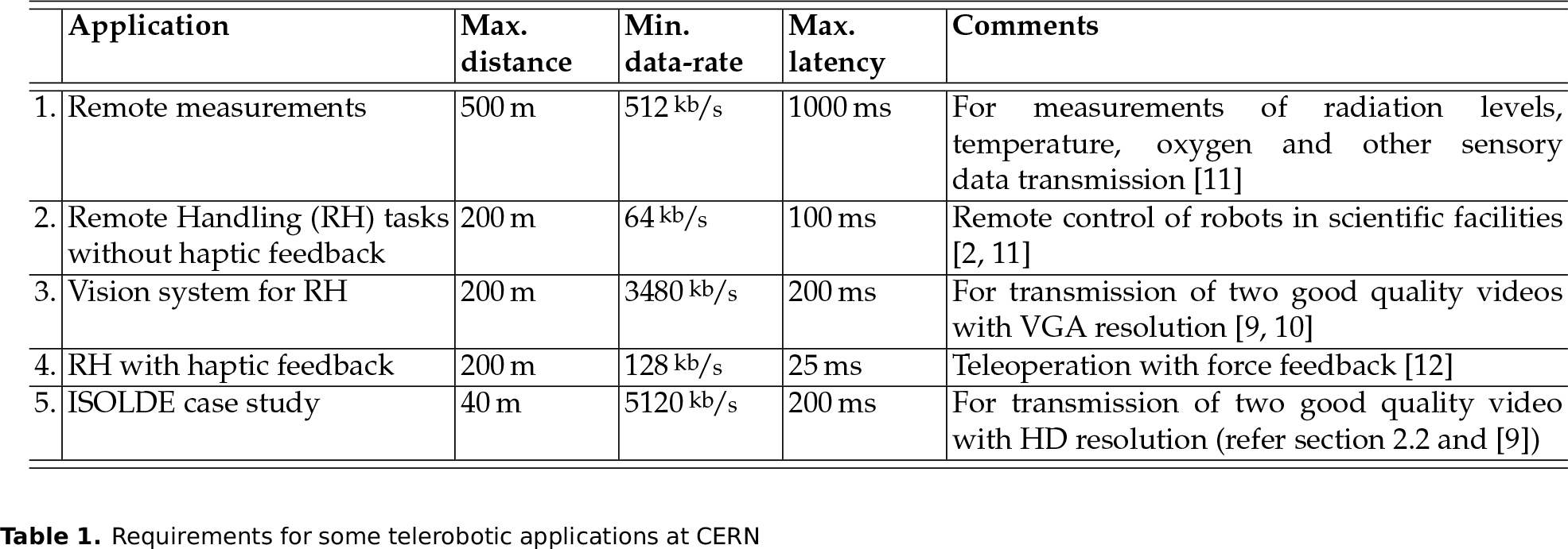
Therefore, considering the need for having two good VGA quality videos and using H.264 coding at 30frame/s, the data-rate required will be 1.7Mb/s [9] per video. Similarly, for other applications, the appropriate data-rate is calculated assuming typical data requirements. Table 1 summarizes the wireless communication requirements for various mobile robot applications at CERN.
2.2. ISOLDE vision system for remote handling
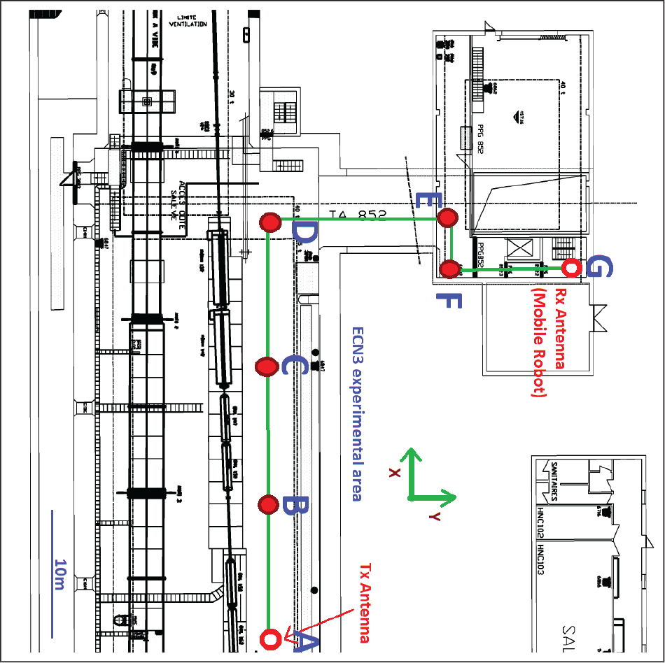
The ISOLDE (the Isotope Separator On-Line facility at CERN) experimental area is one of the high radiation areas at CERN with a radiation dose-rate of 100 mSv/h at 50 cm from the radioactive target after 1 hour of decay [13]. Figure 1 shows the floor plan of the ISOLDE area.
Two industrial STAUBLI RX 170 robots are used to transfer the used targets [14] from the target irradiation supports (C,D) to the target storage area (G) and pick up new targets from (B), a target interchange point. These robots are preprogrammed and the operator selects the sequence of operations from a dedicated control room (A) outside the ISOLDE facility.
However, in some situations such as robot teaching, the operator has the need to visually monitor the robot's movements. For such real-time monitoring, it is desirable that a reliable wireless video transmission system mounted on a small mobile robotic vehicle, such as the KUKA Youbot [15], is used to transmit the live camera feeds monitoring the industrial robots. In Figure 1, the red portions indicate the area where this application is needed.
Requirements for some telerobotic applications at CERN
The communication requirements for this application (given in Table 1) are based on the HD transmission of two good quality videos so that the operator can observe the environment in more detail, including any small sparks in the Faraday cages inside the ISOLDE facility. In this paper, the vision system application at ISOLDE is used as a case study.
3. Comparison of various wireless technologies
Comparison of different wireless technologies is discussed in [16–20]. Table 2 shows a brief summary of specifications of some wireless technologies with the advantages and disadvantages with respect to the ISOLDE case study requirements.
Out of these available systems, a Wi-Fi-based system had been selected for first trials as it was readily available, widely studied and well used technology. Coded Orthogonal Frequency Division Multiplexing (COFDM)-based Wi-Fi technology can be well suited for tunnel environments [21] because it is specifically designed to combat the effects of multi-path interference (see section 4.1). However, owing to availability and cost limitations, a normal Wi-Fi system has been chosen for the experiments.
It appears from Table 2 that a Wi-Fi system meets the requirements for the ISOLDE application, however, the specifications in Table 2 are given for a normal indoor environment, whereas the CERN application will be in a tunnel environment including large metallic objects. As a result, experimental analysis is needed to verify the suitability of a Wi-Fi-based vision system in the ISOLDE area.
4. Radio signal propagation
4.1. Radio signal propagation theory
According to Shannon's capacity theorem [23], in a wireless system, the communication channel capacity C is related to the signal's received power PR as follows:
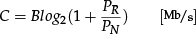
where, B is the bandwidth of the channel and PN is the power of the noise in the channel. This indicates that the data-rate of the wireless network (which is a measure of the channel capacity C) depends on the received signal strength.
When a radio signal travels from a transmitter to a receiver through multiple paths subjected to reflections, diffractions and refractions in the surrounding environment, a phenomenon called multi-path propagation occurs. This leads to multi-path fading and constructive or destructive interference [24]. The multi-path fading can be either long-scale fading due to the shadowing effects caused by the obstacles or small-scale fading due to interferences of the multi-path components [25].
The attenuation in the power of the radio signal is defined as the path loss PL and is caused by many factors such as distance (free space loss), penetration losses through walls and floors, and multi-path propagation [26]. In particular, all walls, ceilings and other objects that affect the propagation of radio waves will directly impact the signal strength and the directions from which radio signals are received. The path loss can be modelled as a log-normal distribution [24]:
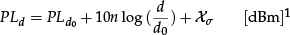
where, PLd is the path loss at a distance d, PLd0 is the path loss at a reference distance d0, n is the environment specific propagation constant, and σx is the variance of a zero mean Gaussian distribution χσ. The n and σx together define the environment and the χσ represents the large-scale fading because of shadowing effects [25].
The received signal power PR is equal to the difference in the transmitted power PT and the path loss PLd over a distance d,

The path loss is a major component in the analysis and design of the telecommunication system [27].
Performance characteristics of commercially available communication systems with reference to CERN requirements

4.2. Radio signal propagation in tunnel environments
Much literature exists for radio signal propagation in tunnel environments [5, 6, 28–30]. Experimental studies on radio propagation characteristics in tunnel-like environments date back to 1975; Emslie et al. [31], focus on the path loss of radio signal at frequencies in the range of 0.2 to 4GHz along a tunnel, and from one tunnel to another around a corner. Reference [5] provides a detailed analysis of wired and radio communication systems in underground mines or tunnel facilities where the tunnels are not straight leading to different forms of turns (e.g., U turn, angle turn). In [6], the authors investigate the communication considerations from the perspective of in-mine and mine to surface communications separately, and provide a detailed overview of all types of possible communication systems.
In [30], the authors recommend a wireless system operating at a frequency greater that 2GHz in underground tunnel facilities because the transmission loss becomes very small over a frequency of 2GHz in a coal mine tunnel of width 4m and height 3m. Therefore, a Wi-Fi system operating at 2.4GHz should be a reasonable choice for underground scientific facilities.
Scientific facilities such as those at CERN, exhibit the characteristics of underground tunnel structures and complete non-Line of Sight (NLOS) conditions with special properties such as heavy metal objects in the surroundings. The presence of thick concrete blocks (for shielding gamma rays, which also makes it difficult for the radio waves to penetrate) and large objects with metallic surfaces such as the dipole or quadrupole magnets, contributes to the characteristics of these environments. All these characteristics have different effects on radio signals [5]. For the facilities having obstructed indoor environments, multi-path effects have to be taken into account in the propagation of radio waves [25].
Boutin et al. [29] analyse the NLOS propagation in tunnels and compare the characteristics of path amplitude and delay spread in a received signal from multiple paths. They suggest that further narrow-band and wide-band measurement campaigns should also be undertaken in galleries with different configurations as the wireless propagation in underground mine tunnels can be a challenge to model accurately in view of the complexity of the environment. Signal propagation simulation tools such as WISE [32], predict the received signal in an indoor RF channel. However, such tools rely on many parameters and are limited to outdoor and LOS situations.
One of the observations by Chou et al. [33] suggests that for a wireless link there is a trade-off between the maximum achievable data-rate and the packet delivery latency. The latency of radio propagation in scientific facilities was not studied in the literature.
The two main motivations for conducting the experimental analysis are:
According to [29], using the theories and analysis available in the literature, it is not very simple to quickly predict the signal propagation behaviour in underground environments because the characteristics for each environment are very different.
No study was found that analyses the effects on radio signal latency in scientific and tunnel facilities.
Therefore, experiments have been conducted to investigate the spatial, temporal and environmental characteristics of radio signal strength and latency in a scientific facility at CERN.
4.3. Communication quality measurement parameters
The quality of communication links is a function of many variables including location, distance, direction and time [34]. To estimate the distance coverage of radio signal propagation, we must analyse the Received Signal Strength Indicator (RSSI) and Link Quality Indicator (LQI) at the receiver end. The latency of the communication network can be measured by using the Round Trip Time (RTT) metric. The definitions of the three metrics to be measured are given below.
RSSI: Corresponds to the received strength of the signal. The signal strength mainly depends on the antenna output power and the distance between the transmitter and the receiver.
LQI: Shows the quality of wireless connection. There are several definitions for LQI and it usually refers to the percentage of packets transmitted successfully.
RTT: Round trip time for a packet to travel from the transmitter to the receiver.
Both the RSSI and LQI are nonlinear with respect to distance as there are many other factors affecting link quality such as reflections and interference. If there are too many wireless stations in a wireless network, interferences may occur resulting in loss of messages. Reference [35] explains why RSSI alone is not enough as a measurement parameter as the interference experienced on a link cannot be inferred via RSSI measurements, but can be measured by the LQI. Therefore, both RSSI and LQI are needed for link quality assessment, and RTT is needed for latency measurement.
5. Experimental setup
Since there is relatively little propagation measurement data available for underground environments, it is important to take into account the impact of various environmental characteristics so that several simulations of link qualities using empirical values can be performed [29]. Conducting experiments at ISOLDE was not allowed during its operation as it is a highly radioactive area [13]. Therefore, experiments are conducted in a tunnel area called ECN3 (shown in the figs. 2 and 3) which was not in operation and hence was available for tests.

ECN3 tunnel area at CERN - location of the transmitter (Point A in Figure 6)

ECN3 tunnel area at CERN - view from the tunnel entrance
Even though the ISOLDE and ECN3 facility areas are different, using ECN3 as the test facility allowed experimented and analytical techniques to be developed, and will provide information on how well results obtained in one facility (ECN3) can be applied to another one (the ISOLDE area).
5.1. Methods and materials
In these experiments one static wireless transmitter (ProSafe Dual Band Wireless-N Access Point WNDAP350 [36]) and five compact Wi-Fi receiver stations are used (Zyxel NWD2105 [37]). The transmitter [36] uses IEEE 802.11n 2.4GHz standards with maximum transmit power PT = 20dBm and a maximum data-rate of 144.44 Mb/s. The receiver [37] had a receive sensitivity threshold RS of −64dBm at Mb/s and −82dBm at 11 Mb/s.
The transmitter was fixed at point A in Figure 6 and the receiver stations were mounted at different positions on a KUKA Youbot mobile robot as shown in Figure 4. The omni-directional capability in Youbot [15] made it the best choice for the experiments because of space and size restrictions in the environment. As for the CPU, a computer running on Ubuntu in the Youbot is used.
The values of RSSI and LQI were obtained by using the iwcon fig command in Linux. Each RSSI and LQI sample is measured at 100 Hz sampling rate for 1s, and then averaged to diminish statistical temporal fluctuations.
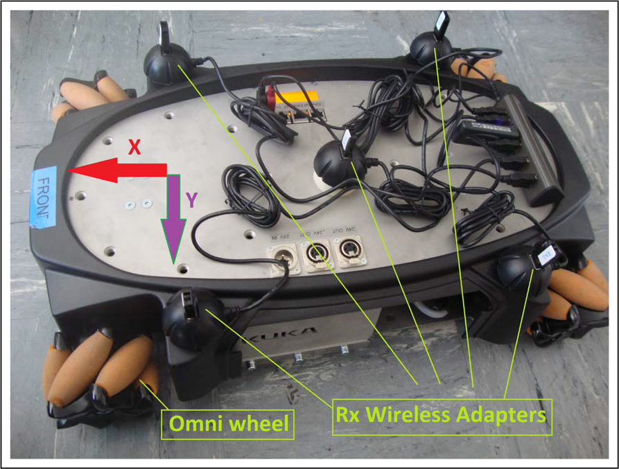
The Youbot mobile robot used in the tests

The ping command provides the RTT values for the respective receivers. The maximum number of bytes able to transfer at a time using ping is 65527 bytes (512 kilobits). The RTT reading for each receiver is the average of 10 samples. The average of the results from all receivers has been obtained, so that the results were not device-dependent.
5.2. Experiments carried out
The variations of signal strength, link quality and the latency in the wireless channel were investigated for temporal, spatial and environment-based characteristics. The three types of experiments conducted were:
Temporal characteristics: Time variation of RSSI and LQI was measured for around 90 minutes at various distances in the ECN3 tunnel. The RTT variation with the amount of data transmitted was also observed.
Spatial characteristics: The mobile robot was moved from one point to another point over a distance of around 50m through variations in space, such as LOS and NLOS situations, passing nearby metallic objects. The robot was moving at a speed of 0.2m/s.
Environmental characteristics: The mobile robot was moved under a reinforced concrete block and near to large metal objects and the RSSI variations were noted.
Figure 6 shows the floor plan of the ECN3 tunnel area and the location of the transmitter and the receiver (Youbot) indicating the path the mobile robot used to travel a distance of 37m in X direction (LOS) and 28m in Y direction (NLOS). Each experiment was conducted twice and the readings were averaged.
6. Results and discussions
Changes in RSSI and LQI with respect to time, distance and environment variations are detected. The RTT variations were measured with respect to the distance and the quantity of the data transferred. The results of these experiments are described in the following sections.

RSSI variations with time at various distances
6.1. Temporal characteristics
In [34], the authors say that it is highly possible to conserve the quality of a wireless link within an hour and they observed RSSI variation within 5 – 6dBm in a day, however this was in an indoor environment. With the measurements shown in Figure 8, the RSSI variation over a period of 90 minutes at point B in the ECN3 tunnel had a mean of 23.22dBm and a variance 8.75 dBm.
Figure 5 shows the temporal variation of RSSI at different distances from the transmitter. It can be observed that as the receiver was farther from the transmitter, the frequency of RSSI variations with time got smaller but the magnitude of variation became larger.
The variation of RTT with distance and quantity of data transmitted (at a distance of 40m) can be observed in Figure 7 and a linear fit for this variation is given by the equation:

This result correlates well with the observations in [10] where the RTT was observed as 1s for transmission of five good quality video images at 2 Mb/s each over a distance of 50m.
6.2. Spatial characteristics
The received signal power RSSI and the link quality LQI with respect to the distance have been analysed in order to understand the spatial characteristics of the radio signals in underground CERN facilities. It can be observed in Figure 9 that the decay of RSSI with distance followed the log-normal distribution as expected [24].
The points in the Figure 9 correspond to the physical location points in Figure 6. As soon as the robot entered the NLOS region (point D), the decay became more rapid with distance compared to the LOS region. As the receiver moved further into the deep NLOS region (point F to point G), the wireless network became unreliable because the RSSI values reached very near to the sensitivity threshold of the receiver (–82 dBm).
The linear regression method described in [24] was used to derive the empirical path loss constants. The n value was obtained by equating the derivative of mean square error estimate Jn of the path loss constant to zero,

The σx value was calculated by substituting the estimated n value in the following equation:

Floor plan of ECN3 tunnel
The reference distance used in calculations was d0 = 5m and the received power at the reference distance was Pd0 = −32 dBm. The path loss constant n and the variance of the Gaussian distribution σx calculated using the experimental data from Figure 9, are shown in Table 3. The obtained path loss constants for the LOS, NLOS and deep-NLOS regions in ECN3 correspond to the outdoor region, obstructed factories region and obstructed in building regions in [24].
These empirical values which correspond the environmental characteristics of ECN3 tunnel can be useful in predicting the distance range of the wireless network in tunnel areas similar to ECN3. It is assumed that the propagation characteristics of ISOLDE experimental area are similar to ECN3 area, therefore the derived log-normal fit can be used in the analysis of the case study application.
Experimental values of path loss constants


RTT variation with quantity of data at various distances
Figure 10 shows the behaviour of LQI versus distance. When the robot entered the deep NLOS region (point F), the link became unstable with very poor connectivity and the LQI decreased linearly with distance d. The linear-fit equation for LQI variation with distance greater than 38m was:

According to [38], the Packet Reception Ratio PRR which is equivalent to LQI, should be at least 85% to consider the link as being of a good quality. Applying the threshold of 85% LQI for a good connection, the distance range for a good quality wireless link in the ECN3 tunnel was 48m from the point A.
6.3. Environmental characteristics
Radio signals suffer significant attenuation near some metallic surfaces due to reflections [5]. According to [24], the expected path loss for radio waves obstructed by a 4m metal object is 10 – 12 dBm. To analyse the characteristics of metallic reflections and obstructions, the robot was made to pass a metre wide metallic obstruction as shown in Figure 11. Figure 12 shows the observed changes in RSSI caused by the reflections and obstructions due to metal objects. The end-to-end variance in RSSI was 8.2 dBm, which is consistent with the values in the literature [24].
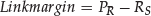
Obstructions by reinforced concrete walls can also deteriorate the radio signal strength as the radio waves find it difficult to penetrate through walls and reinforced concrete materials. The expected path loss because of obstruction by a 0.6m square reinforced concrete pillar is 12–14dBm [24]. Figure 13 shows a half metre thick concrete block used for the experiments. The mobile robot was driven between two concrete blocks and the changes in RSSI due to the obstruction by these blocks were noted as shown in Figure 14. The RSSI variance observed was 17.2dBm which compares to the 13–20dBm path loss due to a concrete block wall in [24].
7. Implications for the case study application
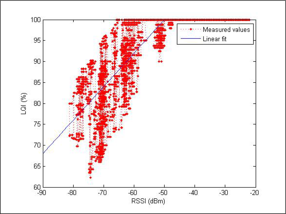
In this section, the question of whether a Wi-Fi system can be suitable for the case study application at ISOLDE is discussed. As defined in [27]: “If the estimated received power is sufficiently large (relative to the receiver sensitivity), the link budget is said to be sufficient for sending data under ideal conditions”. The amount by which the received power exceeds receiver sensitivity is called the link margin.

RSSI and LQI variations with time

RSSI versus distance in ECN3

LQI versus distance in ECN3

Metallic objects used for tests

RSSI variation because of metallic objects

Thick reinforced concrete block used for tests
The wireless communication range and link quality can be improved by one or more of the following approaches [27]:
Increase the “transmit power PT” of the transmitter.
Have enough link margin considering the path loss of the environment.
Relocating or repositioning the antennas.
Among these possibilities, reference [27] recommends that an adequate link margin is factored into the link budget to overcome the multi-path fading when designing a wireless system.
RSSI variation because of concrete block
7.1. Distance range prediction
Let us assume that for the case study application the transmitter antenna is located at a point which ensures LOS connectivity to all the points where the receiver robot can be placed. A link margin of 18dBm is required to ensure 99% link availability (as a percentage of time) in LOS conditions [27].
For the ISOLDE area, a link margin that corresponds to the inevitable RSSI fluctuations due to temporal variations and objects within the LOS has to be considered. This means that for the receiver used in tests with sensitivity threshold RS = −82 dBm, a strong wireless connection 99% of time with an RSSI stronger than −64dBm is maintained in LOS situations.
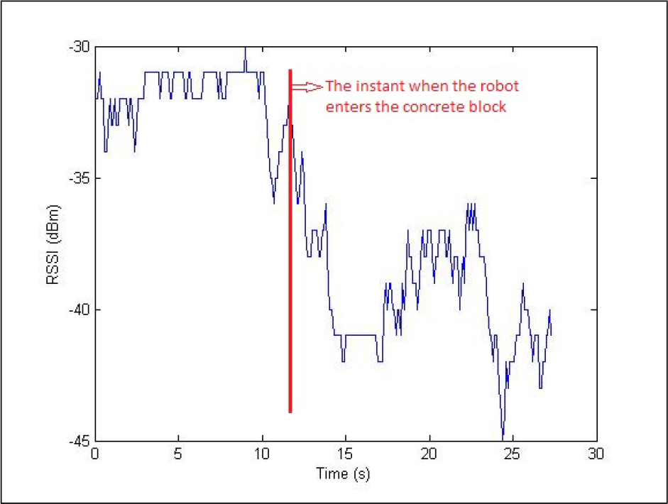
The variation of LQI with respect to the RSSI in the ECN3 tunnel is shown in Figure 15. A linear fit for LQI with respect to the RSSI was applied for RSSI values less than −40 dBm.

It is evident from Figure 15 that to achieve a completely stable and reliable connection where LQI = 100%, the RSSI should be greater than −57dBm in a 95% confidence interval. This RSSI value corresponds to a distance of 35m in Figure 9.
To satisfy the distance requirement of the case study application, an RSSI value of −57dBm is required at 40m distance. In Figure 9, at 40 m, the RSSI value is −60 dBm. Therefore, the need for having an additional 3dBm in the link budget can be solved by increasing the transmitter power from 20dBm to 23 dBm, the legal limit of maximum transmitter power (equivalent to 200 mW) in Europe for the 2.4GHz ISM band. Therefore, a more powerful transmitter or a receiver with better sensitivity threshold, according to theory, can be used to solve the problem of meeting the distance range requirements of the ISOLDE vision system application.
7.2. Data-rate and latency prediction
For the ISOLDE application, a data-rate of 5 Mb/s is required to transmit two HD quality video images. This means that within one second 5120 kbits should have been transmitted. Applying the data requirement at 40m distance in Equation 5, the RTT value is obtained as 514ms, which can lead to two inferences.
LQI with RSSI
5120 kbits of data can be transmitted within one second, therefore, this system will satisfy the data-rate requirement.
Since the RTT = 2 * Latency, the system latency is 257 ms at 5120 kb/s, therefore, a latency requirement of 200 ms is not achieved.
However, when transmitting multiple packets with less data in each packet, the latency requirement can be met. Assuming that data are sent at 4Mb/s, the system latency will be 200ms which meets the latency requirements for the case study application but not the data-rate requirement. Therefore, there is a trade-off between the latency and data-rate requirement in a wireless application.
Table 4 summarizes the requirement and the observed possibilities for the case study application at ISOLDE.
ISOLDE case study application: Needs and calculated requirements

8. Conclusions and further work
This study attempted to characterize radio signal propagation in a typical underground scientific facility for a telerobotic application. Initially, the wireless communication requirements for typical telerobotic applications at CERN and similar scientific facilities are discussed. Considering the requirements for the application of wireless video transmission, we attempted to answer the question of whether readily available wireless technologies such as Wi-Fi, offer adequate performance and can be used for the case study application. Experiments have been performed to analyse the temporal, spatial and environmental characteristics of the radio signal propagation in the ECN3 tunnel area at CERN using link quality measurement parameters such as RSSI, LQI and RTT.
The data-rate requirement for the ISOLDE case study application can be met with the present Wi-Fi-based system used for the experiments. The distance requirement can be met only under LOS conditions, whereas the latency requirement can be met only if the quality of the transmitted videos is reduced. With all the observations, the conclusion is that the Wi-Fi devices used in the experiments can be used for the ISOLDE vision system application only if there is a trade-off between the latency and data-rate requirements, or if a powerful wireless transmitter and receiver (with better transmit power and receive sensitivity) should be required.
The HD video is needed because the video quality is sufficient enough to inspect small cracks in the target or the beam dump in the ISOLDE area. As inspecting a crack with a delay is acceptable, for such inspection, the latency requirement does not need to be met strictly, but the data-rate has to be strictly met. On the other hand, for teleoperation of the robot, the HD video may not be strictly required and so the video quality can be reduced to meet the strict latency requirements but with a trade-off to the data-rate.
Even though the experiments were conducted in the ECN3 tunnel area, the results have given intuitive meaning with regard to how to design a better wireless system in the ISOLDE facility. The ISOLDE area will be available for tests during the long shut down period (May 2013 - March 2014). For further studies, the use of directional antennas (on both the transmitter and the receiver robot) will be examined so that the radio signals from the transmitter are concentrated only to the receiver, thereby increasing the received signal strength.
Footnotes
21. Acknowledgements
This research project has been supported by the Marie Curie Fellowship of the European Community's Seventh Framework Programme under contract number (PITN-GA-2010-264336-PURESAFE) and the Telescale (DPI2012-32509) grant funded by the Spanish government.
The authors would like to thank the Handling Technologies section (EN-HE-HT) at CERN for their cooperation and guidance in this work.
1
dBm (dBmW) is the power ratio in decibels (dB) of the measured power referenced to one milliwatt (mW).