
Abstract
This work addresses the problem of traction control in mobile wheeled robots in the particular case of the RoboCup Middle Size League (MSL). The slip control problem is formulated using simple friction models for ISePorto Team Robots with a differential wheel configuration. Traction was also characterized experimentally in the MSL scenario for relevant game events. This work proposes a hierarchical traction control architecture which relies on local slip detection and control at each wheel, with relevant information being relayed to a higher level responsible for global robot motion control. A dedicated one axis control embedded hardware subsystem allowing complex local control, high frequency current sensing and odometric information procession was developed. This local axis control board is integrated in a distributed system using CAN bus communications. The slipping observer was implemented in the axis control hardware nodes integrated in the ISePorto Robots and was used to control and detect loss of traction. An external vision system was used to perform a qualitative analysis of the slip detection and observer performance results are presented.
1. Introduction
Traction control is becoming a relevant problem in RoboCup Middle Size League (MSL) competitions. In this robotic competition a team of autonomous land robots without external sensors or human intervention must play soccer in a semi-structured environment.
With the increasing size of the fields in the RoboCup MSL, the empty space increases as well(robot number and dimensions are constant). This causes both the players and the ball to cover wider distances. This factor, along with advances in perception and robot mechanics, has lead to a substantial increase in game dynamics and hence in having higher accelerations and decelerations from the robots to play the game effectively.
Therefore, traction optimization is becoming a relevant issue since traction forces at the wheel-ground interface are critical for the robot to achieve a highly dynamic performance. In addition, a decrease in slippage also leads to higher energy efficiency and improves odometry information.
Traction optimization is also relevant to detect game events that cause changes in the wheel-ground interface. These can be, for instance, pushing or being pushed by another robot, collisions with players or fixed structures, or ground unevenness. If undetected and if they are not considered in the decision and control process, these events can lead to: excessive motor currents (stall) frequently exceeding battery and power system maximum values, mechanical degradation, game rule violations (such as faults) or unnecessary energy loss and localization problems due to odometry errors [1].
This work intends to contribute to the development of a distributed active traction system addressing the problems referred to previously.
Early studies on autonomous vehicle motion control relied only on kinematic models [2]. With the development of new sensors allowing a better world perception, it was possible to improve motion [3]. However, part of this work focused on the study of motion dynamics for path tracking. Other lines of research have relied on computing suitable trajectories in the face of road holding constraints and varying terrain topography [4].
Terrain (irregularity) poses additional problems in autonomous vehicles which are subjected to dynamic conditions. This can occur due to trajectory dynamics (induced moments and forces) or by variations in surface-wheel contact properties (due to terrain unevenness) [5]. Stringent performance requirements, combined with the traction problems mentioned above, introduce motion degradation and slippage. Therefore, avoiding slippage conditions while preserving motion as much as possible within the required performance is a necessary step. When traction loss cannot be avoided, it must be dealt with appropriately either by relaxing motion requirements or using a motion planning strategy [6][2].
To the majority of the authors in the literature the objective of traction is to reduce the slip rate between the surface and the wheels. This makes it possible to minimize power consumption, improve motion control performance (trajectory tracking) and overall vehicle safety (reducing the vehicle's effective braking distance). Many technologies have been developed in order to reduce the slip and improve the adhesion performance for any wheels or surface conditions. Such technologies include: optimal slip ratio control [6], Model Following Control (MFC) [6], current disturbance observer [7], sliding mode measurement feedback control [8], slip ratio fuzzy control [9], slip controllers based on disturbance observers [10], back-EMF motor control [11] and road conditions estimators [12][13][14]. In all control algorithms presented, the wheel speed and vehicle speed are required, with the exception of the back-EMF, which requires the motor's intrinsic parameters.
Considering the present state of the art, this work proposes two major lines for improvement:
Extensive slip characterization in an aggressive (highly dynamic) scenario, such as the Middle Size League (presented in section 4). Slip occurrence in the context of the MSL is just starting to be addressed [15]. This will have great relevance in the forthcoming change imposed by the RoboCup where the carpet surface will be replaced by artificial grass. These issues are not specific to the MSL scenario and are common in applications with wheeled mobile robotic systems in a wider range of scenarios.
Developing the necessary skills in prio-preceptive motion control. These are required for high performance motion in highly dynamic situations. Research on the prio-perceptive characteristics of robot control is still required. In a similar approach to bio-inspired control, this work is part of a larger framework where this prio-perceptive motion control plays a relevant role in the application of mobile robotics in extreme environments and for high motion performance situations. To support this approach, and contrary to the approaches mentioned above, the solution provided does not require prior knowledge and modelling of the wheel-ground interaction. This approach presents a more “reactive” system using low-level information available in the control of each wheel, namely odometric and electrical current information. This system should monitor and detect relevant variations in these parameters and react, at wheel level (see section 3), both in a timely fashion and according to the detected event.
In order to validate this approach, several typical MSL events in terms of traction were experimentally characterized (presented in section 4). Multiple events are perceived from the qualitative and visual analysis of electrical current and wheel velocities. This characterization motivates and provides insight on the phenomenon analysis, along with the analysis of simple friction models (see section 2), to develop a slippage observer and to elaborate a traction control system architecture. The slippage observer is developed using information at motor (wheel) level. Therefore, it has a wide range of applications (it is not tied to a particular wheel or robot configuration). This work proposes a distributed hierarchical architecture for motion and traction control. At wheel level, a high frequency loop in the control hardware makes it possible to detect events quickly and to immediately react to control those events. This leads to slip minimization in adherence situations and reducing over-currents in wheel blocking. In addition, information on adherence and events is relayed to higher levels of control. This information is used in the active guidance and control laws, and can determine transitions for the active manoeuvres leading to adequate responses to events. The experimental characterization, the tests and the validation were performed using the ISePorto Team Robots in the RoboCup MSL scenario. These robots have conventional wheels in a differential wheel configuration powered by electrical DC motors. The traction study for this wheel configuration, used in the ISePorto Robots, is more suitable in comparison to the more popular omni-directional wheel MSL robots, as it can be applied more easily to other outdoor land-based robots. Although the MSL scenario will be the scenario used, similar problems arise in other mobile robotic applications, not only in land robots, but also in other scenarios such as marine surface robots. It is important to highlight that the work can be extended to Autonomous Surface Vehicles (ASV) [16]. These vehicles have multiple applications, including patrols, underwater mine hunting, harbour security and defence, oceanographic and environmental monitoring, bathymetry mapping, pollution control, and rescue missions. All scenarios where the operator is absent and the vehicle is remotely operated, or where control and monitoring missions are performed autonomously, are important [17].

Autonomous Surface Vehicle ROAZ I with embedded hardware DATCOS
The traction control architecture and the embedded hardware (DATCOS) presented in section 3 were applied to the ROAZ I (see Figure 1) [16] in order to prevent effects such as cavitation by controlling active thrust. To minimize the thrust reduction propeller axial flow and propeller blocking in fishing nets. They were also used to minimize Wagner's effects occurring in the presence of waves and periodic loss of propeller immersion. These phenomena in water propulsion are similar to slip occurrence (section 4.1), blocking (section 4.2) and wheels not touching the floor (section 4.7) in wheeled traction.
The paper is organized as follows: section 2 focuses on the traction concepts that are required to solve the traction problem characterization presented in section 4. Section 3 introduces the traction system architecture implemented in the Middle Size League robots focusing on hardware issues. Section 5 presents the observer state algorithm used to determine the slipping condition. Section 6 presents the validation of slipping occurrence in the robot motion with an external measuring source.
The paper concludes with a short discussion on the results obtained and outlines topics that may be studied in the future.
2. Problem Formulation
In general, the dynamics of a robot depends on the dynamics of the terrain where it moves. For instance, outdoor locomotion must typically account for loose soil conditions, for instance, when moving on sand. These conditions cause the robot to slip. In such cases, it is necessary to identify suitable models for the contact between robot and terrain surface. However, in a fair number of applications, namely indoors, the terrain is often rigid, with time invariant dynamics. This is the case for the RoboCup MSL competition which motivated the work presented in this paper. Nevertheless, the robots must perform harsh manoeuvres when playing, requiring high accelerations. That may cause the wheels to slip, reducing the traction. The control systems are then required to compensate for the disturbance introduced by the wheel slippage. Moreover, prior knowledge on the characteristics of the contact between the robot's wheels and the terrain surface is in general difficult to identify, which makes it hard to include these features when designing motion controllers. For a mission to be properly executed, it is desirable that traction is maximal in order to maximize the conversion of energy from the motors into motion. Therefore, the wheel slippage must be kept to a minimum, which also improves the quality of the odometric information. Multiple wheel slippage detection strategies are described in the literature. Whenever there are unactuated wheels connected to encoders, slippage can be detected by comparing their velocities with those of the actuated wheels (see for instance [18]). A high level strategy may come from combining information from the IMU (Inertial Measurement Unit) and the GPS (Global Positioning System) with information from the encoders and the robot's model, see for instance [19], for a strategy using Extended Kalman Filtering.

Forces applied to the ISePorto Player
Figure 2 illustrates the main forces acting on each actuated wheel of the ISePorto Robots. Mw, Fd, N, Fm, and Vw stand, respectively, for the torque applied by the wheel actuator, the friction force at the point of contact between the wheel and terrain surface, the weight supported by the wheel, the propulsion force at the contact point generated by the torque applied by the wheel actuator, and the angular velocity of the wheel. For the sake of simplicity, for the slippage analysis, the wheels are assumed to be rigid. Furthermore, the dimensions and physical properties of the wheels and of the rest of the robot are assumed to be time invariant. As such, masses and inertia do not vary. The effect of the castor passive wheels in the overall dynamics is also assumed to be negligible, their purpose being only to maintain the necessary static stability. It is worth highlighting that the model can easily be extended to account for the castors, namely by considering the weight transfer that occurs when braking and accelerating between the actuated wheels and the castors. However, the general principles developed below still apply. This is identical for more complex dynamic conditions, for instance, when the inertia of each wheel varies along the trajectory, when the vehicle is requested to perform a tight curved trajectory that deforms the wheels or the structure of the robot, or when the type of contact between the wheels and the floor varies along the trajectory. A single wheel model was used in order to design a slippage detector/observer. Note that there is no lack of generality with this approach. In fact, each wheel of a generic robot can be equipped with a slippage detector. If the detector depends on configuration parameters, it is possible to use high level learning strategies to adjust the performance of the global detector to different terrain conditions.
The friction force Fd is assumed to be of Coulomb type,

where N and µ respectively stand for the contact force between the robot and the ground (normally to the surface at the contact point), and the static friction coefficient, and V is the linear velocity of the wheel written in its own frame. More complex friction models could be used, such as the one developed by Dahl and LuGre [20]. Although both models require parameters such as shape-stress curve and stiffness coefficients, information will only be available if several tests are performed. As such, this is not coherent with the proposed approach. The force balance equation (absolute values) yields
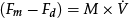
The force driving the wheel, Fm, is generated by an electrical actuator as
with Km, Imotor, and r representing, respectively, the intrinsic parameters of the motor, the electrical current, and the wheel radius. Using (3) in (2) yields

Assuming that the friction properties are constant during the movement, slippage is characterized by a sudden decrease in the friction force. Differentiating (4), with Km and M assumed constant, provides the basic way to detect slippage

When İmotor < 0 and V̈ > 0, slippage occurs for certain as the wheel's linear velocity increases when the motor requires less power. If İmotor < 0 and V̈ < 0, there may also be slippage, depending on the relative values of the terms in (5). However, such a case is of no practical interest to the purpose of this study. This means that the linear velocity of the wheel increases at a decreasing rate when the power required by the motor is reduced. The pratical result for such a situation amounts to a wheel slipping slowly, which in fact is in accordance with Fd, which tends to have a smaller absolute value than when İmotor < 0 and V̈ > 0.
This seldom occurs in the MSL robot competitions as the robots have a relatively low weight. To detect slippage, we are interested mainly in the sign of the terms in (5) (though a threshold on Ḟd must also be used to avoid disturbances leading to erroneous detections).
However, differentiating the observed velocity twice, V, may increase noise effects. Therefore, a strategy is proposed below to estimate the sign of V̈ without differentiating V̇. Assuming that the control system of the robot specifies a linear reference velocity for the wheel, Vref, which can be positive/negative without losing generality if the wheel is moving forwards/backwards. In the RoboCup MSL competition, slippage is more likely to occur when velocity reference commands are sent for the wheel to change its velocity as this implies sudden accelerations/decelerations.
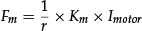
The current reference velocity, Vref and its variations, ΔVref, define eight conditions of interest for the observed wheel velocity, listed in Table 1.
Conditions on the reference velocity Vref
Conditions 1a and 4b represent fast accelerations, whereas conditions 2b and 3a represent fast decelerations. Conditions 1b and 4a represent slow accelerations, whereas conditions 2a and 3b represent slow decelerations. Fast accelerations and decelerations represent the conditions where the probability for slippage is higher. This is visible in sgn(V̇). In a sense this provides an optimistic form of detecting slippage and provides the foundations for the slippage test described in the following section.
3. Traction Control Architecture
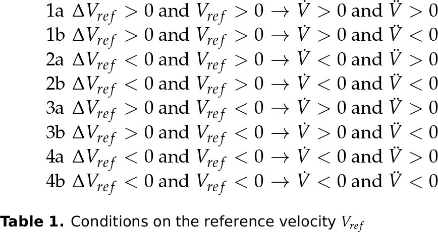
The traction control architecture is characterized by two hierarchical levels of action (see Figure 3). The lower level is implemented in a dedicated hardware solution in each wheel. It implements local axis control allowing force, velocity or position feedback. It is responsible for reducing the occurrence of slip, optimizing the torque applied to the motor and sending all relevant information, both continuous values and discrete events, to the higher level via CAN. This allows the high level control manoeuvres to deal with and adapt to the detected event. Global motion control is performed at a high level. At this level there is knowledge on the robot's wheel configuration and the appropriate velocity or force references, which are sent to each traction axis in order to perform a specific motion manoeuvre. In the higher control level it is possible to use information regarding loss of adherence or other characterizing events from the lower level so as to select the appropriate manoeuvre or tune parameters accordingly. The high level control manoeuvres are usually implemented in a central processing system and can also use additional information from other sensors, such as accelerometers or navigation subsystems, to further characterize robot motion.
Detecting motion problems makes it possible to correct and adapt the path[21] or the control manoeuvres. The architecture is also distributed in the sense that it implies the lower level axis control to be implemented at each wheel, possibly in separate controllers with some level of local slip control. This separation of physical implementations allows flexibility in terms of robot applicability.
Traction System Architecture
3.1. Traction Control Hardware
New motion controllers and power drives were developed not only to improve traction control, but also the overall robot reliability. The new axis control node DATCOS (Distributed Active Traction Control System), which is based on a hybrid DSP (Digital Signal Processor) with a CAN (Controller Area Network) interface (see Figure 4), makes it possible to reduce the number of cables, providing torque measurements for traction control. The DATCOS is small-sized (4cm × 4cm), low-powered and provides computational capabilities supporting relatively sophisticated control algorithms, such as slip, velocity and traction/force with a high rate at 1KHz.
3.2. ISePorto Robot
The slipping detection observer described in section 5 was implemented in the distributed embedded system motion control (DATCOS) in the ISePorto soccer robots (see figures 4 and 5).
The robots have conventional wheels in a differential traction arrangement powered by electrical DC motors. The traction control study for this traction configuration applied in the ISePorto Robots has the advantage over the more popular omni-directional wheeled MSL robots being used in many other land-based robots with conventional wheels. This is even more relevant in outdoor terrains where the presented observer will improve the navigation quality. Each driving wheel has a motion control unit performing the slipping estimation, implementing a wheel motion control loop and connected by a CAN bus [22]. In addition, this embedded controller also integrates the motor power driver. The main robot CPU controls the global motion issuing references to the control nodes and reading relevant information. The current ISePorto main computer is based on a single-board computer running a RT-Linux operating system and high level navigation and coordination software.

Axis control node DATCOS developed by the ISePorto MSL Team
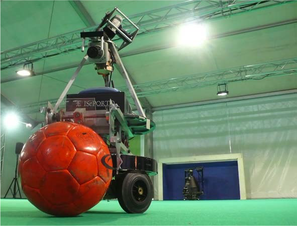
ISePorto Robotic soccer player
4. Traction Issues in the Middle Size League
In a middle size game the robots are exposed to dynamic variations in adherence [20] values between the surface of the field and the wheels. This is caused by events such as pushing, blocks, collisions and crossing of the field lines. All these disturbances can be observed in the current and velocity values at each wheel. A set of tests were realized using an ISePorto Team Robot in order to characterize the referred slip affecting events occurring in a soccer game. The tests where conducted in a middle size field and all the motor control nodes (DATCOS) were connected to a CAN bus with a baud rate of 1Mbit. The DATCOS performed the current and odometry acquisition with a sample time of 1kHz. The electrical current acquisition was made with a 12bit A/D converter and odometry with a quadrature decoder, giving 5000 ticks per wheel turn. The current and the odometry were filtered using an Equiripple FIR filter of order 4. The values applied to the filter were calculated using the Remez Exchange algorithm [23]. In all tests step voltage references were applied to the traction motors in open loop in order reduce the controller-induced disturbances in the detection analysis.
4.1. Acceleration
In this test, robot acceleration is presented for an initial stopped position in response to a step motor reference. This corresponds to a typical robot motion event leading to potential slippage. In Figure 6, it is possible to observe the instant when the slip occurred, as well as its period, during an acceleration process. Some loosing/recovering traction cycles can also be observed during a period of 0.25s.
The slip is characterized by an abnormal low current and high velocity.
4.2. Blocking
This test corresponds to the situation where the robot collides with another robot and is capable of pushing it. Blocking occurrence is characterized by an increase in load.

Slip occurrence in acceleration

Blocking caused by robot or obstacle
This phenomenon requires higher traction and therefore has higher probability of reaching adherence limits causing slipping (see Figure 7).
4.3. Pushing
This experiment corresponds to the robot being pushed by another robot when moving.
Pushing presents a measured velocity value greater than the reference used by the application and low current in relation to the expected velocity (see Figure 8).

Pushing by another robot

Reverse the goalkeeper motion
4.4. Motion Reversal
Motion reversal occurs when a robot suddenly reverses its veleocity and is a frequent goalkeeper movement, as it moves mainly in both directions in a small area.
Without traction control, it is possible to observe that it takes almost 1s to reverse the motion and recover traction again (see Figure 9). This delay makes the goalkeeper vulnerable to the possibility of a goal.
4.5. Braking Process
In this experiment, a reference command was applied from maximum value to zero. The braking process in the ISePorto Robot can be observed in Figure 10.

Braking process in ISePorto Robot
The robot takes 600ms to stop without the traction control system. This is caused by the robot's low adherence between the field surface and the wheels. With the traction control system, it is possible to reduce the slipping period, improving not only actuation, but also the quality of the localization and navigation.

Left-side collision with handspike occurrence
4.6. Collision
Lateral Collision with a Moving Robot
Lateral collision presents two different behaviours. The robot can either present a lateral force that will influence the motion, or a handspike occurrence that will cause one wheel to lose contact with the field. This will cause an increase in friction force (see Figure 11).
Collision with Fixed Landmark
In the collision with a fixed landmark the robot will present low or zero velocity depending the its position in relation to the landmark (see Figure 12). The current increases and maintains a higher value.

Collision with a landmark
In the previous experiments a fixed landmark was used and after the collision the robot turned left. This can be observed in Figure 12 because the right wheel maintains a low velocity and the left wheel is stuck.
Collision with Still Robot
A collision with a still robot is different from a collision with a landmark as the robot can overcome the inertia imposed by the other robot. A slower velocity increase and a slower current decrease will occur. This does not occur if the robots collides with a fixed obstacle (see Figure 13). The test presented in Figure 13 was performed using two robots with different weights. The still robot with 40kg and the collision causing robot with 20kg.

Collision with a still robot
4.7. Wheel without Contact with the Field
During a middle size game it is usual for the ISePorto Robot and an opponent to become stuck and one or both wheels to lose contact with the ground (see Figure 14).

Left wheel loses contact with the field
The loss of contact of one or two wheels with the ground, if undetected, usually introduces relevant errors in the navigation system when odometry is used. This occurs as a result of the inherent shortcomings of the odometric process even when integrated with other localization sensors. Since higher level control keeps the wheel reference signals, when the wheel regains traction the robot suffers a sudden unexpected movement. This will cause degradation in the localization of the robot in the field, mainly in short-term heading estimation errors.
4.8. Slip Over the Field Line Marks
Due to the fact that field line marks are implemented with plastic strips laid over the carpet ground, robot motion over them can be affected.
It is only possible to observe a slip over a field line mark when the robot is in an acceleration/braking process. If the robot is moving at constant velocity, the disturbance caused by the lines is not detected (see Figure 15).
4.9. Unevenness of the Ground Field
During the MSL games field degradation occurs and Figure 16 expresses the instant when the left wheel encounters uneven ground.
This disturbance will cause motion degradation which in turn will influence the path defined by the higher level control application.
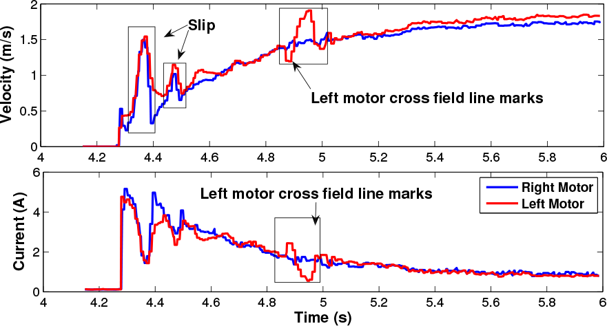
Left motor cross the field line mark
4.10. Wheel Characteristics
A comparison between two types of wheels with different adherence properties is presented in Figure 17. On the left figure, it is possible to observe a higher adherence comparatively to the one on the right for a test with an accelerating step followed by a motion stop. Adherence is higher (Figure 17 left) as the current for lower velocities increases as the robot starts moving.

Ground unevenness field only in the left wheel

Relation between velocity and current with two different type of wheels.
This leads to a higher friction force and thus to a higher torque load on the motor. On the right, it is possible to observe periods of slippage as “cycles” on the current/velocity “descent phase”. Traction loss is represented by a sudden increase in wheel velocity and decrease in current (a friction force). When the wheel regains adherence the velocity decreases and the friction force condition is resumed.
4.11. Remarks
In the analysis performed, normal motion events such as acceleration, braking or motion reversal can lead to slippage when friction limits are reached. This is characterized by a sudden increase in wheel velocity and consequent decrease in current. These cases will be addressed at the wheel level by reducing motor reference command in order to regain adherence. When detected, the reaction should be quick and should take place on the local control loop. Other events occurring in the MSL scenario are changes in friction properties between the wheels and the ground, either due to surface changes such as crossing lines or terrain unevenness. In these cases, the slip should also be addressed at low level control as slips are transient motion disturbances.
Another different situation occurs when one or more wheels lose contact with the ground. Here, the slip behavior occurs for a potentially long period of time and it must be dealt with at the global robot motion control level. Therefore, it is necessary to convey this information to the central processing system. The event will then be considered in the localization process to reduce energy loss and also to avoid sudden mechanical loads caused by the wheel regaining contact. This can be performed by stopping the motor.
The blocking situation is caused by a robot colliding with an obstacle. This obstacle can be either a fixed landmark or another player. Collision with an opponent player in the MSL can be translated as a game fault when the charge is prolonged or violent. In the case of collision with another player, depending on the adherence conditions, the player may be pushed. In these cases, slippage can initially be dealt with at a wheel low level, and if it is persistent, this corresponds to the robot being stuck either by colliding with a fixed landmark or with another robot with higher traction. Persistence slippage must be dealt at the higher level of robot motion control. Persistent load increase can lead to mechanical or electrical damage and should be prevented at robot level by changing the current motion manoeuvre.
A similar situation occurs when another player pushes the robot. In this case, the cause for the disturbances is wheel velocity and motor torque load and thus in current lead to the slip phenomenon. This must be dealt with by the high level robot control since it is not a transient event and cannot be solved at wheel level.
5. Slippage Observer
For highly dynamic robot scenarios such as the robotic soccer environment, the terrain surface characteristics and robot dynamic conditions restrict the use of standard literature models for quantitative friction force description. These scenarios are not as complex and therefore cannot represent the richness of the robot dynamics. Furthermore, they are also more costly in relation to the information provided. However, the models provide qualitative information which makes it possible to interpret the evolution of robot dynamics. Therefore, using Equation 4 and a state defined by the motor current Imotor and wheel velocity V, an algorithm (observer) is presented to determine the slipping condition. The algorithm observes the evolution of the variable and their transitions occurring in a topological frame (hierarchical information), detecting the different phases expressed in the friction force.
The information process hierarchy leads to four discrete states which determine the wheel friction condition: adherence, slipping, acceleration and braking.
Slipping process - Slipping process - characterized by a significant decrease in motor current Imotor and by a drastic increase in wheel velocity V. When the robot enters this state, friction force is reduced, which leads to a loss of adherence areas and to an increase in velocity.
Adherence process - characterized adherence areas on the surface. In order to regain adherence, an increase in friction force is required. In these cases, there is an increase in current Imotor and a reduction of wheel velocity V.
Acceleration process - characterized by an increase in current Imotor and wheel velocity V. This state occurs when there is a transition from a static friction force condition to a dynamic friction force condition. When the wheel is accelerating it can go from an adherence to a slipping condition depending on the friction capability of the wheel/surface.
Breaking process - characterized by a decrease in current Imotor and an increase in wheel velocity V. When the wheel brakes it goes from a dynamic friction force condition to a static force condition. The ability to regain the connection points depends on the physics of the wheel/surface.
The observer provides an index (DATCOSTCS) characterizing the friction condition and this was implemented in the embedded distributed motion control system for the ISePorto Robots [22].
A set of thresholds configured at the initialization stage are used to determine when a CAN bus message is sent to the robot global motion controller containing the corresponding friction state and index value (see Figure 3).
The performance of the algorithm implemented in the DATCOS embedded system can be observed in section 6.2. The qualitative analysis with an external vision system on the developed slippage observer is visible in section 6.4.
6. Results Using an Exogenous Slipping Condition Observer
In the experimental work described above 4 the slip occurrence in differential drive DC electricity-powered mobile robots was studied. This made it possible to understand the phenomenon associated with the traction process and provided insights on the traction control architecture and on the development of a traction control system. Nevertheless, the identification and validation of slipping in the robot motion required an external motion measuring source. An experimental setup was implemented combining an external computer vision process to obtain the required information, as depicted in Figure 18, and the data on the axis control node DATCOS.
An ISePorto Robot was used in the tests. The computer vision system provides information on the robot's position. This made it possible to determine the velocity and orientation of the robot. Simultaneously, information on the motor current and encoder odometry is recorded for each traction motor/wheel. The synchronization between the two CPUs, robot and an external computer, used in the experimental setup was achieved using the Network Time Protocol (NTP) [24]. The NTP was a requirement to achieve time accuracy and reliability in the experimental scenario.

Experimental setup
The robot's position and orientation was determined using two circle markers (orange and blue) with a fixed distance detected in the overhead image (see Figure 21). In order to achieve good vision based on the robot's position accuracy, it was necessary to determine the geometric and optical characteristics of the internal camera (intrinsic parameters) [25], as well as the 3D position and orientation of the camera frame relatively to a certain world coordination system (extrinsic parameters) [26] and precise colour segmentation. The image processing steps are summarized in Figure 19.
6.1. Physical Setup
The experimental physical setup consists of one USB Philips camera at 15 FPS with 640×480 resolution, blue and orange 15cm diameter circular markers, an Intel Pentium Dual Core PC with 2GHz and 2GB memory for image acquisition and processing, and a RT Linux operating system. The ISePorto experimental robot setup is the hardware presented in section 4 plus the triaxial MicroStrain 3DM-GX1 accelerometer. A test target was used in order to verify the external vision system image acquisition quality, with particular emphasis on the colour segmentation precision. This target had the following characteristics:
Full 30cm circle markers
Inter marker distances is 25cm in x and in y 33.5cm
Target to camera distance 2.78m

Image processing

Know target for accuracy test

Circular markers image segmentation
By analysing the identification of markers (Figure 20), it was possible to find a medium error of 20mm. This error validates the external vision tracking system as a suitable measurement setup for the intended purpose.
6.2. Embedded Control System Slipping Observer
The following section will describe the state observer performance implemented in the embedded system DATCOS motion for wheel state detection. In Figure 22 on the left it is possible to observe velocity and current graphs for each wheel, while on the right it is possible to see the observer performance.
Having analysed the graphic, it was possible to observe the occurrence of slipping on the right wheel, with the corresponding identification by the observer at instant 4.19s. Information from the observer implemented in the local motion control board (DATCOS) is transmitted via CAN bus to the higher robot motion control level with the message Event Status (see Figure 3). In Figure 23, it is possible to observe the behaviour of the embedded algorithm system detection transitions related to Figure 22. The four regions represented in the Figure 23 are the possible states identified by the implemented algorithm. High dispersion is observed in two regions, traction and slipping. A movement without disturbances in terms of adherence loss implies a lower dispersion in the figure presented with a highly concentrated set of points around the origin. The observer performance was measured for a different set of wheels with higher adherence capability. The data are presented in Figure 24. In Figure 24, slipping and traction instants are identifiable by the observer at 4.2/4.4s and 4.3s respectively.

Slipping observer performance
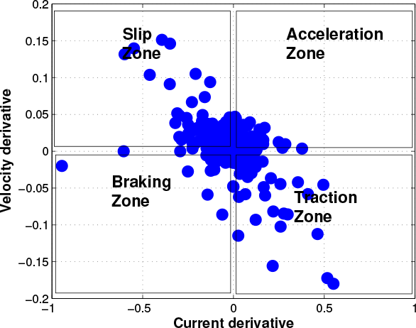
Region transitions detected by the observer algorithm implemented in the DATCOS embedded system
This analysis made it possible to determine the “quality” of the robot's movement, verifying absence of significant slippage, as having low dispersion in the points presented in the previous figure. The non existence of slipping instants (as detected in Figure 24) would imply a further reduction of dispersion with a high concentration around the origin.
6.3. Traction Tests Using an External Vision System
This section presents the results obtained with the external vision system, the triaxial MicroStrain 3DM-GX1 accelerometer and the embedded motion system data. Comparing vision data with velocity measurements, it was possible to obtain highly coherent results, validating the embedded system that gathered the information.
In Figure 26 slipping occurs with higher incidence on the right traction wheel, which causes disturbances in the robot's motion at 0.8m. In the braking process, friction force and wheel velocity variations are detected. Adherence and slipping instants are identified in Figure 26 from time 9.8s to 10.2s.

Observer performance for higher quality wheels(higher friction)

Region transitions detected by observer algorithm in the embedded system for second wheel set

Robot movement for a 1.2m/s reference

Robot movement for 1.2m/s reference
In Figure 27 it is possible to confirm that most of the time the robot motion does not present slipping. The only exception is during the braking process with the transitions identified between adherence and slipping. The external vision system does not make it possible to identify disturbances in each traction wheel, presenting only a global decrease in velocity. By analysing the three figures, the results of the embedded system are confirmed by the external motion data collected.
6.4. Qualitative analysis - Slipping Observer vs. External Vision System
This section presents a qualitative analysis for the slipping with the data collected by the external vision system. Figures 28 and 29 demonstrate the traction wheel behaviour with information given by the embedded motion control system and external vision tracking.
The figure plots identified by Right wheel slip or Left wheel slip present slippage captured by the external vision system and by the embedded motion. Figure 28 shows that even in low reference commands slipping has occurred with higher prevalence around time instant 5.25s. This event was promptly identified by the observer algorithm implemented in the embedded system.

Slipping obtained by vision comparing with the observer algorithm data for a 0.5m/s reference command

Slipping obtained by vision comparing with the observer algorithm data for a 1.2m/s reference command
Figures 28 and 29 show that the embedded system detects slippage in accordance with slipping instants detected by the external system. During the braking phase, it was possible for the embedded system to identify loss of adherence in accordance with the external vision. However, a performance increase in the detection algorithm would be expected if the measurement of current included signal. Here only an absolute value for motor current is measured.
7. Conclusions and Future Work
The problem of traction in mobile wheeled robots in the RoboCup MSL league scenario was analysed in this paper. In particular, this work provided a study on slip occurrence in differential drive DC electrical-powered mobile robots. Traction control problems in this scenario have a much wider applicability in mobile robotics. Traction loss was characterized for the set of possible game events, ranging from excessive acceleration to collisions. The analysis was performed using high rate (1KHz) measurements of electrical current and odometry in each motor using the distributed local control axis/power system (DATCOS). This characterization, along with simple friction models, motivated a discrete slipping observer proposal along with a hierarchical motion control architecture. The approach to overall traction control relying on electrical current data, combined with motion data, does not depend on prior knowledge on the operating surface or the robot's motor model. In addition, traction control is achieved in real time and in a distributed form. The embedded slipping observer for the mobile wheeled robots was analysed in this paper. An experimental setup based on an external computer vision system was implemented providing an independent source of motion data and allowing a qualitative analysis. The overall motion control infrastructure is already implemented and tested in RoboCup competitions. This infrastructure makes it possible to reduce slip by detecting discrepancies in current and motor velocity, and as a consequence reducing reference commands. It also relays to higher hierarchical levels the information required to re-plan the motion when necessary. By comparing vision data with the detection of slipping events, it was possible to confirm that the results are highly coherent, which validated the embedded system detection. Local slip control is currently implemented, validated and tested in operational conditions and should be tested in additional scenarios. Higher level response to drastic traction problems is currently under development. RoboCup competitions will present a relevant scenario for these validation tests. In the future, the system can be further developed by including the dynamic robot model in the higher level response. The developed slippage observer, combined with specific motion control hardware, will make it possible to develop an adaptive generic traction control system in the future where occurrence rate events could be used as feedback in a terrain learning strategy approach. This would allow for the robot to adapt itself to specific terrain characteristics and define accelerating ramps according to the detected event rate. This work was also extended to other robotic motion control applications, particularly to marine robotics, preventing effects such as cavitation, controlling active thrust and minimizing thrust reduction due to the propeller's axial flow.
Footnotes
8. Acknowledgment
The authors acknowledge the major support given by the ISEP-IPP Institution, by the INESC TEC, to this project. This work is financed by the ERDF - European Regional Development Fund through the COMPETE Programme and by National Funds through the FCT - Portuguese Foundation for Science and Technology within project FCOMP-01-0124-FEDER-022701.