
Abstract
The function and performance of MEMS are affected by the output ability of the displacement and force of microactuators. The lateral deflection of cascaded V-shaped electrothermal actuators is modelled as a triple, statically indeterminate problem. An iteration algorithm is set up to calculate the output displacement and typical forces in anchors. The calculated results of this model agree well with our own simulation results as well as with the experimental and calculated results in the literature, and we conclude that the model is credible. The paper also discusses the effects of the structure parameters and temperature increments on the displacement production ability. Clear differences were found between single and cascaded V-shaped electrothermal actuators. For the former, the maximum deflection takes place in a 0.04 rad beam angle, while for the latter the beam angle is 0.19 rad. For both types of actuators, the deflection is unrelated to the beam thickness. The displacement of the cascaded V-shaped electrothermal actuator is proportional to the temperature increment and beam length, but is inversely proportional to the beam width. Experiments on the output ability of cascaded V-shaped electrothermal actuators validated the calculated and simulation results.
1. Introduction
The microactuator is an important part of Microelectromechanical Systems (MEMS) that is used for energy conversion, motion generation and force production. Its displacement and force output is critical for microsystem devices to perform their functions. The electrothermal actuator works by the principle of thermal expansion [1,2]. In V-shaped electrothermal actuators, the thermal expansion caused by joule heat pushes the apex outward when the electric current passes through the beam fixed by its anchors. The desired output force and displacement are obtained by adjusting the electric input parameters [3]. The force generated in the V-shaped actuators is large (up to several hundred mN). Other benefits of the V-shaped design are a lower drive voltage, a larger deformation and a simple structure. Thus, V-shaped actuators are widely used for micro-valves, micro-pumps, grippers, and other micro devices.
Gianchandani et al. [4] first developed V-shaped bent beams in the design of a microsensor. Que et al. [3] developed single and cascaded V-shaped electrothermal actuators (henceforth to be abbreviated as V-shaped actuators). When the current passes through the beam, the power can be calculated by the formula W = I2R. Since the thermal capacity of the thin beams is small, a quick and large thermal expansion is generated by heating, which produces the required force and displacement at the apex point of the V-shaped actuator. Que presented experimental results where the secondary beam of the cascaded V-shaped actuator carried no current, but did not provide an analysis model. Park et al. [5] used the V-shaped actuator concept to develop a grinding rotary electrothermal motor, shown in Fig. 1, on the basis of Que's study. They also developed the one direction creep displacement magnifying mechanism with the use of four single V-shaped actuators.

Rotary motor driven by thermal actuators [5].
Zhang Yongyu et al. [6,7] established separate static models for single V-shaped actuators based on the strain method and the force method, respectively. Enikov et al. [8] discussed the heat dissipation problem. Chu et al. [9] further researched the life of single V-shaped actuators. Hsu et al. [10] used multiple single V-shaped actuators in series to form a V-shaped actuator array so as to provide large displacements. Zhang et al. [11] developed a macro-model for a cascaded V-shaped actuator whose secondary beam carried no current. Although Zhang considered the issue of heat dissipation, he did not present a static mechanical analytical model for displacement production.
In this paper, an analytical thermo-electro-mechanical model is presented for cascaded V-shaped actuators, where the current-carrying feature of the secondary beam is different from that developed by Que et al. [3] and Zhang et al. [11]. This model not only suits cascaded V-shaped actuators, with the secondary beam carrying no current, but also for cascaded V-shaped actuators with the secondary beam carrying current. Therefore, it has a wider suitability for various cascaded V-shaped actuators. This model is based on our previous mechanical performance analysis and experiments on single V-shaped actuators [6], and it allows designers to predict the deformation and force of cascaded V-shaped actuators before their fabrication. The model brings forth a more complete description of the mechanical performance of cascaded V-shaped actuators, and can be used as a simple and fast design tool for cascaded V-shaped actuators.
2. Modelling
Figure 2 illustrates the schematic structure when applying voltage to the cascaded V-shaped actuator, which is composed of three identical single V-shaped actuators in series. Electrodes D and E, and F and G are connected by wire. The corresponding equivalent circuit diagram is shown in Fig. 3. Due to the equivalent resistance and thermal expansion of the beams, the voltage of the secondary beam (beam BO and CO) is double that of the primary beams (beams BE, BD, CG and CF). Because the temperature increment ΔT is proportional to the voltage square U2 [12], the temperature increment ΔT1 of the secondary beam is four times that of the temperature increment ΔT2 of the primary beams after applying the voltage source between electrodes E and G. As a result, the precondition of mechanical performance analysis is to establish the displacement and force models, analysing their relationship with temperature increments ΔT1.
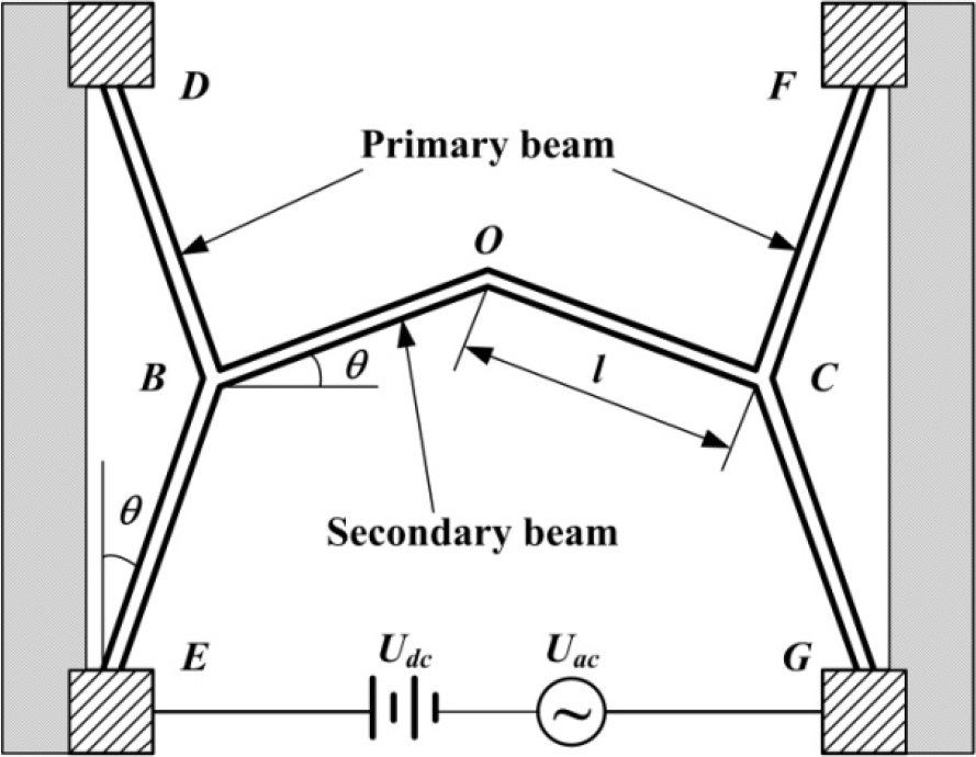
The schematic structure and manner of application of voltage to the cascaded V-shaped actuator.

The corresponding equivalent circuit diagram.
As shown in Fig. 2, the structure is symmetrical in the horizontal direction, so that the tip displacement, which is the displacement at point O, only has the displacement in the vertical direction when no external force is put. The tip displacement is constituted by both the electrothermal expansion of the secondary beam and the effects generated by the electrothermal expansion of the primary beams. The analysis model can be built based on the deformation superposition principle as long as all the deformation is elastic.
2.1 Thermal Model
Zhang et al. [11] developed a thermal model for the cascaded V-shaped actuator with the secondary beam carrying no current by considering the thermal radiation and convection heat dissipation. However, the thermal model for the cascaded V-shaped actuators with the secondary beam carrying current had not been established. It is necessary to build the thermal models separately because the current densities of the primary and secondary beam are different and the temperature distributions are related to the current densities. Many studies have proven that the heat loss of thermal actuators is primarily caused by thermal conduction through the air gap and the substrate, while the heat loss to free convection and thermal radiation is negligible and could reasonably be ignored [13,14]. Without considering the free convection and thermal radiation, the thermal model of cascaded V-shaped actuators with the secondary beam carrying current can be achieved by optimizing Zhang's macro-model [11].
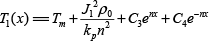
The temperature distribution T2(x) of the primary beam DBE and beam FCG can be obtained by solving the following steady-state heat transfer equation:

where parameter
Solving Eq. (1) yields:
where C1 and C2 are the constant solutions of Eq. (1), which is a differential equation.
The boundary conditions T2(0) = T2(2l) = T∞ of Eq. (2), which are the temperatures at point D, point E, point F and point G, are equal to the reference temperature T∞, where l is the length of the beam. Considering the temperature Tm at point B, there will be Tm=T2(l).
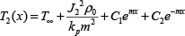
With a similar analysis, the temperature distribution T1(x) of the secondary beam can be written as:
where
With these thermal models, the temperature distributions T(x) of all the beams in the cascaded V-shaped actuator can be achieved, providing the foundation for mechanical models.
2.2 Mechanical Model
2.2.1 Force and Deformation of the Secondary Beam
The force and deformation of the secondary beam are shown in Fig. 4. It is a double statically indeterminate problem because its structure and forces are symmetrical in the horizontal direction. For the secondary beam, the deformation yOl and a set of reaction forces can be achieved according to the results of reference [12]:


Force and deformation of the secondary beam.
where E and I are, respectively, Young's modulus and the moment of inertia for the beam, A is the cross-sectional area of the beam, J is the parameter (J = Al2 sin2 θ + 12Icos2 θ), α is the thermal expansion coefficient (α = 2.33×10⁻⁶/°C), and ΔT1 is the average temperature increment of the secondary beam, which can be written as
The relationships of apex displacements of the secondary beam and the primary beam are shown in Fig. 5. It is also a double statically indeterminate problem. Here, the deformation yO2 and the reaction forces are only caused by the effects generated by the electrothermal expansion deformation x‘B2 of the primary beams, while not considering the thermal expansion of the secondary beam. The equations of force balance can be derived as follows:


Relationships of apex displacements of the secondary beam and primary beam.
From the relation of the deformations in Fig. 5, it can be inferred that:

Similarly, the corner δ'B2 at point B generated by the deformation x'B2 is:

As the structure is symmetrical around the y axis, Fig. 6 can be achieved from Fig. 5. As the effects of axial force and shear force on deformation are very small, they will be ignored and only the moment will be considered. In Fig. 6(a), the moment at location ζ can be obtained by using energy method of Moore's law [15].

Relationships of force and deformation of point B.

From Fig. 6(b), the moment caused by the unit force P1 in the horizontal direction at point B can be expressed as

Similarly, the moment caused by the unit moment M1 in the anticlockwise direction at point B can be expressed as

By solving Eq. (9) and (10), one obtains:

where x'B2 is the deformation caused by thermal expansion of the primary beam; it should be solved from the force balance of the primary beam, DBE. As such, the total forces and moments at point B can be written as:

2.2.2 Force and Deformation of the Primary Beam
The displacements of point B of the primary beam DBE are caused by both its own thermal expansion and the reaction forces (XB and MB) of the secondary beam. The structure, which is counterclockwise turned the angle of 90, is shown in Fig. 7(a), and it is also symmetrical in the horizontal direction, though the force is not symmetrical. Because it is a linear elastic problem, it (Fig. 7(a)) can be considered as thermal expansion in Fig. 7(b), force XB in Fig. 7(c) and moment MB in Fig. 7(d), respectively, in order to overlay those deformations and forces. The problems in Fig. 7(b) and Fig. 7(c) are double statically indeterminate problems, for the structure and force are symmetrical in the horizontal direction. The problem in Fig. 7(d) is a triple statically indeterminate problem. From Fig. 7(b) and Fig. 7(c), XD1, YD1,MD1,XE1, YE1,ME1, xB1 and XD2, YD2, MD2, XE2, YE2, ME2, xB2 can be solved, respectively. Moreover, XD3, YD3, MD3, XE3, YE3, ME3, xB3, y B3 , δB3 can be solved from Fig. 7(d):
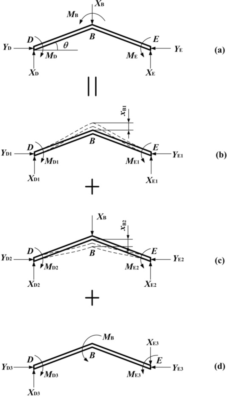
Forces and deformations of the primary beam.
Thus, the reaction forces at point D and E, and the displacements of point B can be expressed as:


where ΔT2 is the average temperature increment of the primary beams (beam DBE and FCG), and
2.2.3 Iterative Solution for Force and Deformation
The displacement xb and corner δ B of the primary beam apex are caused by both its own thermal expansion and the reaction forces of the secondary beam, which it is necessary to assort with x‘B2 and δ’B2 of point B of the secondary beam BOC. Eq. (7) shows that x‘B2 and δ’B2 are connected to each other. So, there is:

According to the analytic model above, the tip displacement at apex O for the cascaded V-shaped actuator can be calculated by:

x‘B2, XB and MB are premised mutually, when the deformation and force are to be solved. The real problem is the dynamic balance of the thermal expansion between the primary beams and the secondary beam. The solution flow chart is shown in Fig. 8, which will continue iterative solving until meeting the convergence of a given precision. This indicates that the stress at the section of point B is the largest, while the B section is most dangerous for the cascaded V-shaped actuator discussed above. It is necessary to have an intensity check in designing the device structure, and to further establish the corresponding objective functions of the structural optimization and design rule.
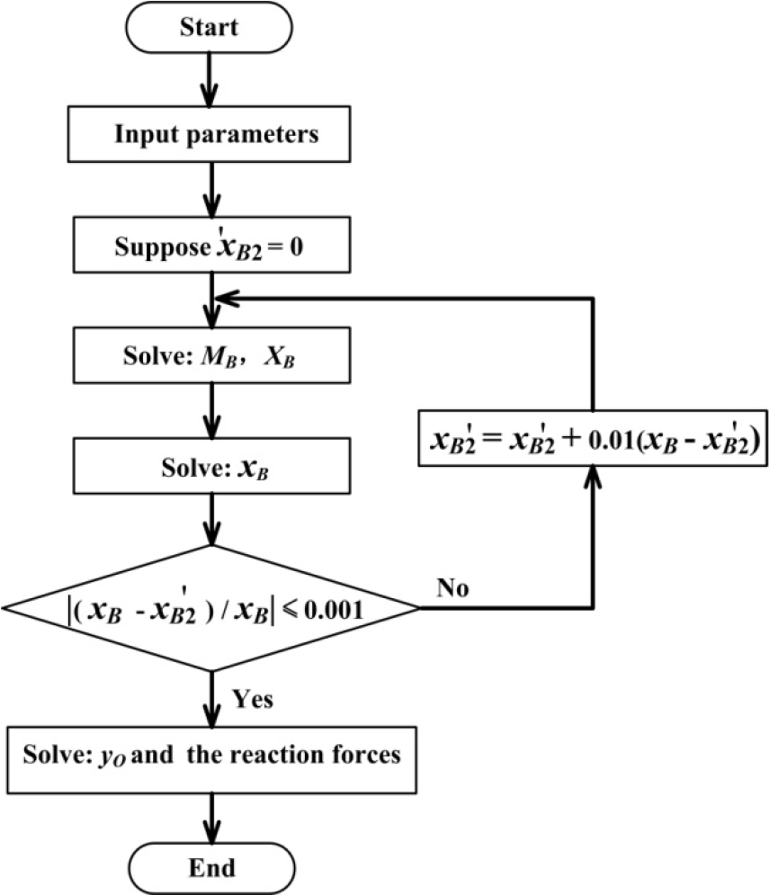
Iterative solving flow chart of the deformation and force.
3. Model Validation
According to the applied voltage manner, there are two forms of cascaded V-shaped actuators, decided according to whether the current exists in the secondary beam or not. Que et al. [3] developed cascaded V-shaped actuators with the secondary beam carrying no current and performed corresponding experiments, but without the analysis model. Zhang et al. [11] only developed a macro-model for the cascaded V-shaped actuator with the secondary beam carrying no current. When the current density J1 is zero, the model established above could be suitable for those cascaded V-shaped actuators with the secondary beam carrying no current. As a result, the model can be used for both two types of cascaded V-shaped actuators. The accuracy of this model can be proven by comparing the results calculated by it with the calculations of Zhang, the experiment data of Que and those achieved from a model simulated by the ANSYS™ software.
Figure 9 presents the tip displacement of cascaded V-shaped actuators with the secondary beam carrying no current as a function of input power. It compares the results calculated by the analytic model in this paper with the calculations of Zhang's model [11], the available experimental data of Que [3] and ANSYS simulations. One can see that the calculations are fundamentally consistent with the others. Moreover, the calculations from the model established above are closer to the experimental value than the calculations of Zhang's model [11], which shows that this model is suitable. The parameters utilized for calculation and simulation are listed in Table 1.

The tip displacement as a function of the input power.
Parameters utilized for calculation and simulation.

4. Performance Analysis of the Cascaded V-shaped Actuator
By applying the solution of yO to Eq. (17), the performance of the cascaded V-shaped actuator can be discussed. The performance of a cascaded V-shaped actuator is related to the process parameters and the geometrical dimensions as well as to the input power. Here, the tip displacement as a function of temperature increments ΔT (referred to as ΔT1), length l, angle θ, width b and thickness t are, respectively, extracted by using the analytical model mentioned above, when the structure is applied with voltage. Fig. 10 shows the tip displacement as a function of ΔT. It is seen from the curve that the displacement output is proportional to the temperature increments.

The tip displacement as a function of the temperature increments (l=230 μm, θ=0.2 rad, b=10 μm, t=2 μm).
Figure 11 shows the tip displacement as a function of the beam length of the actuator. It can be seen that the displacement output is proportional to the beam length. When the beam length is larger, the thermal expansion under the same temperature increment is bigger. In addition, if the working temperature of the silicon beam is higher under the same beam length, the corresponding output displacement will increase.

The tip displacement as a function of the beam length (θ=0.2 rad, b=10 μm, t=2 μm).
Figure 12 indicates the tip displacement as a function of the beam angle. The beam angle value occurring at maximum displacement is related to the structural dimensions and material properties of the cascaded V-shaped actuator. For the cascaded V-shaped actuator with those parameters listed in Table 1, there must be a suitable beam angle to make the tip displacement reach its maximum. Furthermore, Figure 12 shows that when θ is increased from 0 to 0.19 rad, the tip displacement will achieve a large increment. However, when θ is enhanced further, the tip displacement will decrease. In particular, when θ is far larger than 0.6 rad, the displacement will nearly achieve a small decrement. As a result, the displacement will reach the maximum at 0.19 rad, while it will reach its maximum at 0.04 rad for the single V-shaped actuator. Under the same beam angle, the tip displacement increases with the increase of the temperature.
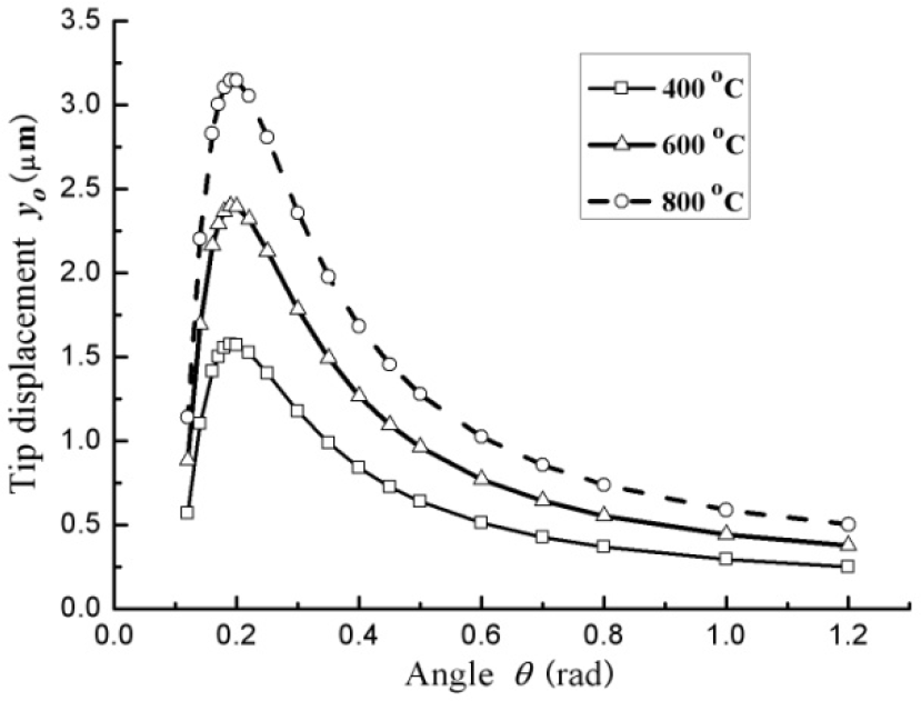
The tip displacement as a function of the beam angle (l=230 μm, b=10 μm, t=2 μm).
Figure 13 presents the tip displacement as a function of the beam width. From the figure, it can be concluded that the displacement decreases during the increasing process of the beam width. It decreases quicker at higher temperatures than at low temperatures. Therefore, the beam width should generally not be too large within the structure's design.
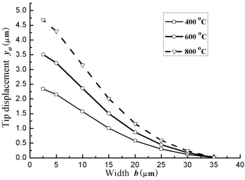
The tip displacement as a function of the beam width (l=230 μm, θ=0.2 rad, t=2 μm).
From the analytical model mentioned above, it can be derived that the tip displacement is independent of the beam thickness, which is the same conclusion for the single V-shaped actuator [12].
When we design the cascaded V-shaped actuator, we can select suitable structure parameters to make its tip displacement larger.
5. Experiments
In the experiment for the cascaded V-shaped actuator with the secondary beam carrying current, the performance parameters measured were the static output displacements. The relationship between displacement and voltage could be determined by adjusting the voltage Udc between two electrodes.
As shown in Fig. 14, the probes are used to apply the voltage between two electrodes in order to get the experimental data. Fig. 15 shows the tip displacement as a function of the input voltage. It can be seen that the results of the experiment, the theoretical calculation and the simulation are fundamentally consistent.

Photo of the cascaded V-shape actuator.

The tip displacement as a function of the input voltage (Resistance15.6 KΩ, ambient temperature 21.9 °C, humidity 33%).
6. Summary and Conclusions
A thermo-electro-mechanical model for cascaded V-shaped actuators is described in this paper. Performance analyses based on the model and experimental results are presented. The following is a summary.
A model for the force and deformation of cascaded V-shaped actuators is built as a triple statically indeterminate problem, and an iteration algorithm is set up.
The calculated results based on this model agree well with our own simulation as well as with the experimental and calculated results in the literature.
According to the model, the tip displacement has a parabolic relationship with the beam angle. The maximum deflection is at 0.19 rad. The displacement is proportional to the temperature increment and the beam length, while it is inversely proportional to the beam width. Moreover, this inverse relationship is stronger at higher temperatures than at lower temperatures. There is no relationship between the displacement and the beam thickness.
Experimental results on the output ability agree with the calculated and simulation results.
For the model, the secondary beam carrying no current is a special case. The model works whether the secondary beam carries electrical current or not. The model can be used for the design of cascaded V-shaped actuators.
Footnotes
7. Acknowledgements
This work is sponsored by the National Natural Science Foundation of China under grant number 51075249.