
Abstract
The use of robotic systems in performing construction tasks has great potential; however the development of such systems remains problematic. This is due to the lack of a suitable feasibility analysis that can help the decision-makers to justify the use of robots and problems in the development process of the system itself. The multidisciplinary and complex nature of construction robotic systems requires a robust development framework for such systems. An augmented framework for the development of construction robots is explained in detail and practically applied to the Starlifter robotic system which is mainly designed to carry heavy tools for construction tasks. The framework consists of two models; the feasibility analysis model and the development process model. The feasibility analysis principles, methodology and tools are explained and discussed in detail. Systems Engineering model is used in the development of the system which allows complete analysis of the system hardware and software components. The purpose of the current project is to develop a general purpose robot that can be employed to perform different jobs to justify its use economically. The presented tools and processes can be utilised in the development of any similar systems.
Introduction
Construction robotics as a research field could be said to have been established in 1984 with the 1st Internatonal Symposium in Automatiuon and Robotics in Construction. Since that time, many research and development activities have occured in many application areas in the construction industry. It is however noticeable that only a small number of construction robots have been commercialised and implemented; reasons behind this problem are identified by Seward, Seward (1999): 1) Nature of construction applications, 2) Absence of integrated IT infrastructure and 3) Conservatism in accepting new technology in construction.
Another reason that could be added to the above is the lack of methodologies and tools that can help in the assessment of new technologies and automated solutions that suit the nature of construction activities. Regarding the third reason, it is required to identify needs and benefits of using such technology in performing construction tasks to convince the decision maker to adopt this new technology.
Four major reasons are identified, based on the work done by Kangari and Halpin (1990) and Thomas (2002), which reinforce the use of automation in the construction industry: 1) Health and safety risk reduction, 2) Improving the working environment, 3) Quality and productivity improving, and 4) Cost reduction
The above reasons obviously reflect the nature of construction tasks which involve hazards that affect personal safety owing to the nature of construction sites or the characteristics specific operational tasks. These hazards generate problems in relation to product quality, productivity and high wages of labour.
Hence the development of robotic systems for construction activities faces many barriers which affect their implementation. These barriers can be classified as technological barriers and economical barriers.
The technological barriers come from the fact that, a construction robot must cope with the complexity of the construction process which involves an unstructured and continuously evolving site together with the performance of multiple tasks with differing characteristics. This in addition to the replacement of human labour which requires the system to have certain level of intelligence in the form of an advanced control system and an intelligent sensory system.
Task wise challenges can come from the fact that it is required that the system adopts traditional techniques of performing a task in order to minimize the number of changes to overal task performance. This requires special technical capabilities to be available in the robotic systems.
The development of robotic systems for construction activities moves in different directions to remove the technological barriers. These directions can be classified as:
Development of mobile platforms and manipulators Development of advanced control systems Sensory systems integration Re-engineering of processes to suit robotic systems Software development to help in the above aspects of development The use of advanced IT systems to enhance the whole system performance
Economical justification of the use of a robotic system in performing construction tasks is the driving force for the final implementation of the system. Economical barriers for the final implementation of such a system come from the requirement of an evaluation technique to cover the following aspects: Neil et al (1993)
The direct cost or benefits The effect of the new system on the organization such as technology strategy complying with health and safety regulations and labour organizations factors The required changes for implementation of the new system
In most cases it is required to remove the technological barriers to be able to adopt an economical evaluation technique. However with the help of feasibility analysis models it is possible to provide guidelines for the decision makers to think about the robotic automation solution.
Many application areas in the construction industry have been identified by previous authors, Kangari and Halpin (1990), Seward (1999) and Thomas et al (2002), as candidates for automation or robotization or as examples of already developed processes.
Seward (1999) listed different areas for automation based on a review of construction robotics developed by Wing (1989). This list includes robotic systems developed in different areas as follows:
Assembly, manipulation and material handling and joining Inspection, maintenance and surveying Spraying, finishing and cleaning Road works and tunnelling Earth works, mining and demolition
The above list was explained in detail with examples of already developed systems or systems still under development. In addition to the above application areas, Kangari and Halpin identified other areas such as, offshore ocean floor construction, excavation for gas line installation and crater repair of bomb damaged runways. Other areas are proposed by Thomas (2002) as candidates for automation based on a questionnaire of people from the construction industry in the North West of England. The results of this questionnaire have identified the following application areas:
Site clearance and waste management Site preparation for safe operation Sub surface works such as deep drainages which includes many hazards Unloading, transport, lifting and commissioning
This work identified many other applications areas mentioned by other authors which mainly include safety risk related applications. The main objective in the Thomas study is to identify areas as candidates for automation to comply with health and safety regulations. Other automation opportunities identified by Kangari and Gregory (1997) and Esposito et al (1993) in the field of military' environmental operations and hazardous waste management. Three areas are specifically mentioned: (1) area clearance (2) unexploded ordnance removal and (3) hazardous waste removal.
The present work is focusing on identifying methodologies and tools to help in accelerating the development process of construction robots. The present work is based on the use of two models, feasibility analysis model and systems engineering model. The feasibility analysis model is designed ultimately to justify the use of robotic automation from different perspectives. The systems engineering model is designated to help in engineering of robotic systems as multidisciplinary systems to comply with the technological requirements identified above. The present work is based on practical implementation of the two models and the use of real life applications and contracts as case studies.
Starlifter robot, the first robot in the world designed specifically for the deployment of heavy tools in construction sites, is used as an example of construction robotics to practically validate the two models identified above.
The Starlifter Robot
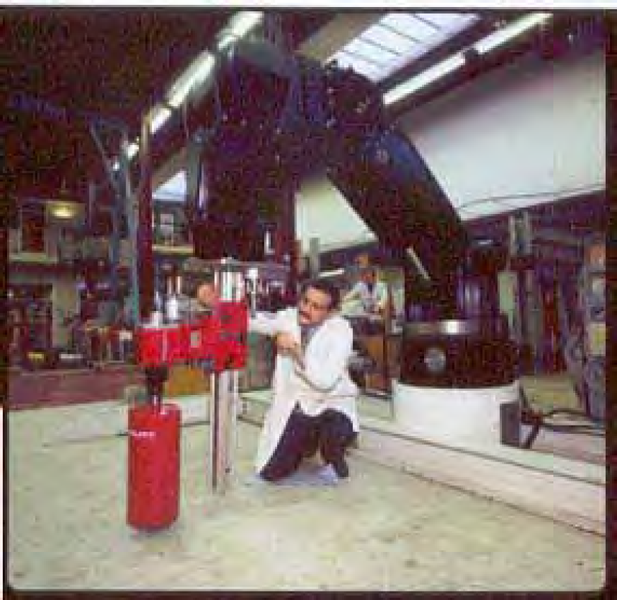
Starlifter® is the first robot in the world specially designed for performing construction tasks - see Fig. 1. In this section a detailed description of the robot is presented in terms of kinematics, drives, control etc. The purpose of this description is to analyse and evaluate the system components to emphasize the robot design philosophy to determine a starting point for the future development.
The Starlifter Robot
There are many design objectives of Starlifter robot such as:
Providing a stable platform for the tool while performing the task Carrying capacity of up to 200 kg at any orientation of joint 1 Portability Re-configurable end-effector Remote control Modularity
These design objectives controlled the size, the weight and the cost of Starlifter robot. For example, designing for a stable platform required a strong and rigid structure of the robot links as well as the robot joints. Designing for a payload of 200 kg required the use of powerful actuators to support the initial weight of the robot and to carry the designated payload. The size of an actuator is proportional to the load it can carry i.e. the bigger the load the bigger the size of the actuator which will be reflected on the total size and weight of the robot. Designing for a re-configurable end-effector and modularity required the use of advanced technology, which results in higher cost. The analysis of the existing system includes the identification of the robot kinematical structure and the components used to drive and control the robot motion.
Starlifter is a six-degree of freedom robot with six revolute joints. The kinematical layout of Starlifter is similar to the structure of an elbow robot described by Paul (1982).
The design philosophy of Starlifter is centred on compactness i.e. the robot arterial connections, valves and actuators must be included inside the robot links. No external hoses and no exposed connections. This philosophy reflected on the size and the shape of the robot links and joints. Box-shaped links are made to contain all the required components inside the links. The outer frames and the side plates of the links are made of steel to support the bending loads induced due to the links self-weight and the payload at the robot tip. The outer case of the links and the joint covers are made of aluminium. Starlifter can reach a height of 3.80 m at full extension from the ground level with the current base structure. This reach can be achieved without any attachment to its tip with full stability of the base structure. This reach can be extended to higher positions according to the attached tool dimensions and weight. Equilibrium and stability of the robot dominates its reach and load capacity.
Hydraulic power is used to operate Starlifter robot to sustain the required payload and the robot inertia. Most large scale industrial and construction robots are hydraulically powered, especially those with high carrying load capacity Hass and Hsieh (1993). Rotary and linear actuators are used to move the robot joints. Starlifter is operated using a standard hydraulic portable power pack, electrically powered by a three-phase power source. This power pack can deliver oil at the rate of 60 litres/min at maximum pressure of 220 bar. The power pack is equipped with a dump valve to cut the output flow when it is necessary while the pump is running. It is also equipped with an emergency stop to cut the power in case of undesired motion of the robot or any other safety related problems.
Three modes of control are used for controlling Starlifter motions. These three modes cannot be used simultaneously. These modes are:
Direct joint control (manual control) Teleoperation control (Joystick control) Pre-programmed motion control (task language control)
The first mode of operation is used during testing and maintenance of Starlifter in which a manual control box is used to send signals to the valves directly using a set of potentiometers. The second and the third modes can only be used through a high level controller called ATC© (Advanced Teleoperation Controller) developed by UK ROBOTICS Ltd. The ATC controller utilizes a PID controller operated by a servo controller.
A series of tests are carried out to prove the functionality against the design objectives. The first test is carried out to test the arm performance while carrying the maximum payload of 200 kg. Fig. 2 shows Starlifter carrying test weights at different configurations of the arm. It can be noticed that the test weight is a balanced weight in which the moment at the end-effector plate is uniform. However these tests are carried out at critical configurations in which a non-uniform moment at the robot links is induced. These tests show great stability of the arm at these configurations. The second test of Starlifter is the payload stability using the actual HILTI tools (up to 120 kg) In this test, the robot shows great flexibility in manoeuvring the tools even for long extensions of the tool rail as in the case of the HILTI plunge saw.
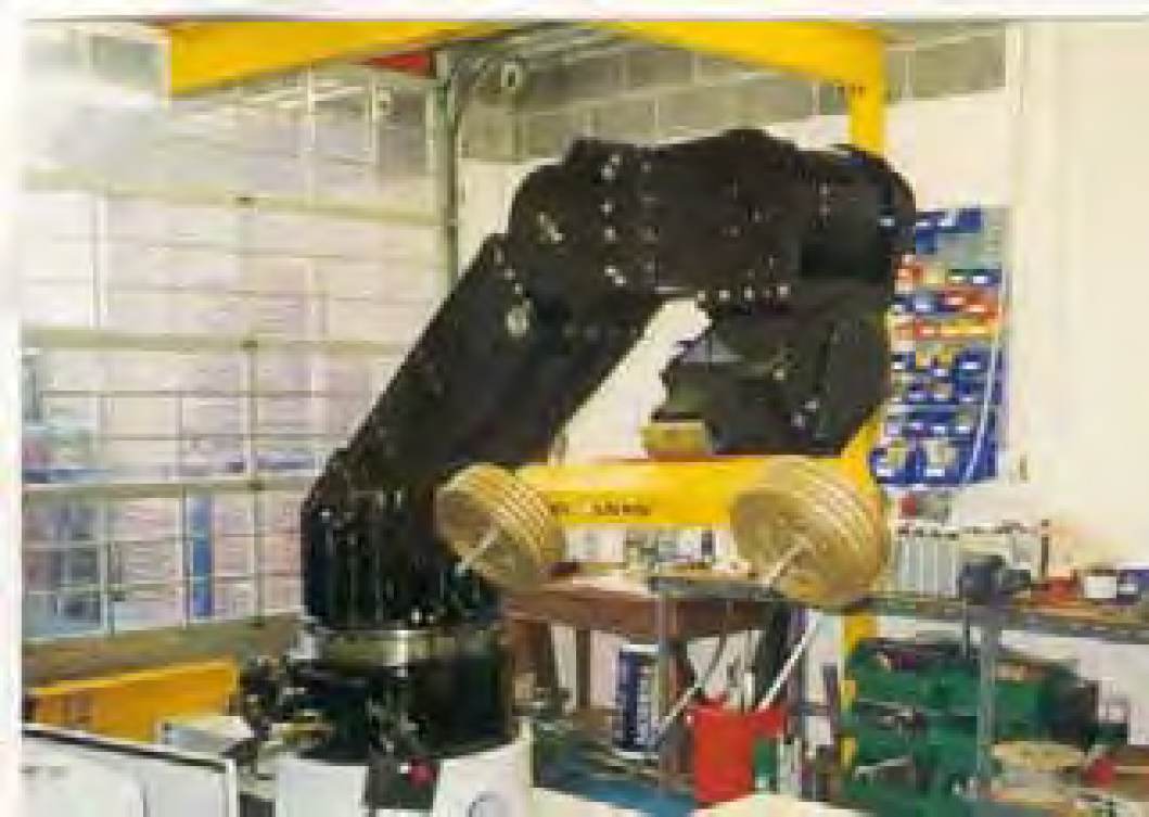
Starlifter payload test
The adoption of new technology in the construction industry must be followed by definite benefits that will motivate the management to take the decision to move forward in using this technology. As an example of these benefits those mentioned above in the comparison between the use of diamond core drilling and the use of conventional methods of demolition in terms of time reduction, structure integrity, labour safety etc. These benefits made the decision makers adopt the diamond cutting technology. For any construction task it is not easy to judge the immediate benefits of using new technology unless a complete analysis and evaluation are performed to define the needs and benefits.
Model description
In the present work, an integrated systematic model is developed to help the decision makers to analysis, evaluate and decide the implementation of new automation technology. The feasibility analysis model basically consists of four stages namely; need analysis, decision-making, technology approval and economic analysis as shown in Fig. 3.
In the need analysis stage, comprehensive analyses should be made to identify the task characteristics and particulars and the level or levels of automation the automated task is going to use. The outputs of this stage are: firstly alternatives for performing the task (this could include the recommendation of use a refined version of the conventional methods of carrying out the task, or even to use the conventional methods as they are). Secondly, selection criteria for the decision making stage for each alternative. These criteria based on risk analysis and operation characteristics identification.
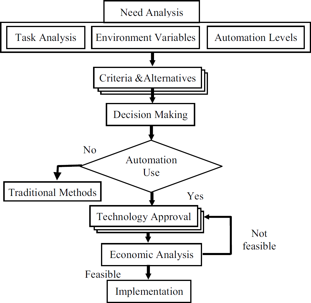
Feasibility analysis model
The alternatives and their selection criteria together are going to be passed to the decision making process which uses methods such as AHP (Analytic Hierarchy Process) which is useful in case of multiple criteria/alternatives problems. Interview-based questionnaires are made with experts or people in the field to which the task under study is related. This approach is usually employed when using the AHP methodology, Saaty, 1980. The alternatives and criteria should be strictly defined for particular cases and not be generic. The experts in the field are knowledgeable of the conventional methods however they should be aware and be given enough information about the new technology; otherwise it would not be easy to get reliable information about the needs and benefits of using such a new technology. Demonstration of the new technology is required to get reliable information. This could be done using existing production versions of the technology, a working prototype or at least reliable simulations of the technology if it is still under development.
The outcome from the decision making process supports the use of one of the alternatives, which could be the traditional method, however if the decision-making process suggested the use of automation, further analysis should be done. For the elected level of automation a technology approval procedure will be employed to identify the details of the automation level in terms of the robotics system requirements to satisfy the working conditions specified in the need analysis process. The robotic system requirements for a certain level include five modules identified by Esposito et al such as Locomotion, robotic platform, sensors, controller and endeffector. These five modules vary from level of automation to another, for example for a basic level of automation; these modules could be reduced to a manipulator, a teleoperator controller and a simple grasping endeffector. For a higher level of automation a mobile platform can be integrated to do the locomotion function with sensor guided controller and automatic tool changer endeffector.
It is necessary to look at the available technology and how far it can be practically implemented. In this stage a detailed architecture of the system must be identified to enable the economic evaluation of the level or levels of automation under study. The economic analysis includes the comparison of the cost associated in performing a task using the traditional methods and the suggested level of automation. The output from the economic analysis stage will approve the implementation of the suggested level automation from the economic point of view or to go back to look to the other alternative technology produced by the technology approval stage and continue the loop until a satisfactory output is achieved. The decision makers' role is very important at this stage because they have tangible results that they can rely on from different points of view.
In the present work a comprehensive feasibility analysis is carried out to justify the use of Starlifter robotic system in concrete core drilling and sawing. The analysis is based on case studies from contractors who use traditional methods. Details of the case studies and the outcome from the feasibility analysis were presented in previous work by Zied and Seward (2003). The feasibility analysis results presented in this was in favour of the use of the automated process.
Earlier study carried out by Zied et al (2001) on the economic feasibility of the use of Starlifter robotic system in core drilling underneath a motorway bridge showed that the robotic solution is more economic in the short term based on hiring the system. The study was based on cost estimation based on graphical simulation of the proposed system. More economic analysis could be carried out for further justification using the same method for other case studies.
The outcome from the feasibility analysis presented here on the whole showed that it is justified for the system to move to the next stage of the development process.
Systems Engineering Model
Background
A robotic system generally comprises many modules that need to work together to perform a task. The required capability range of robots for hazardous environments is very wide depending upon factors such as the nature of the task, the degree of structure in the environment and the level of hazards. The development of advanced technology requires both a study of economic feasibility and an assessment of available technology. The identification of the required capabilities that a robotic system should have is not an easy task and it requires the use of a systematic approach that enables the developer to have concrete information, which can help in satisfying the end user requirements. The adoption of a systematic approach in the development of any system requires the use of an appropriate development model, which takes into consideration the unique nature of the particular construction tasks. The many modules of a robotic system for decommissioning make it a multidisciplinary system in which the selection of a development model based on only one module is not appropriate, Zied, 2004.
The system development life cycle can be illustrated as a sequence of actions to be taken that starts from the system objective and results in the final operation of the system. In between these actions a review of the completed steps in the form of feedback should be made before moving to the next step. The sequence shown in Fig. 4 represents the major components of the sequential development model. In this model, the process is divided into three sections, the first one, which can be called

SE simple sequential model
The sequential model can be overlaid over the SE process described by Thome 2001 to compare the steps in both of the two concepts of development –see Fig. 5. The main purpose of this overlaying is to illustrate the ability of the sequential model for tailoring to suit the system under development.

SE sequential model overlaid on the SE process diagram
The tailoring process of a development model based on the SE process needs knowledge of the main components of the basic sequential model, which as can be seen from Fig. 5 represents the individual steps of the SE principles. In the following section details of the main components of the sequential model are discussed.
The user requirements
The user requirements are the first step in the development process and the finished product should satisfy these requirements. The user requirements drive all the subsequent stages of development and they also tell us what will dominate the future from an operational point of view however, they do not specify how the objectives are achieved.
The system requirements
It is an intermediate step between the user requirements and design stage aiming to show what the system is going to do but without details of how it will be done. The system requirement should be written in a detailed document called system requirements document SRD. The objectives of the document are:
Explaining the whole idea of the system Exploring, optimising and providing alternatives Demonstrating the reflection of the user needs Providing a basis for testing of the final system
The system requirements should satisfy the user requirements and they should be functional and needed. It is possible to find that one component of the system requirements will meet multiple user requirements. It is common to find that users judge the final product according to how well their requirements are satisfied, partially met or even rejected by the product. It is possible to produce a good system requirements document by using the following principles:
Remove unnecessary design decisions in requirements Summarise and localise critical interfaces Aim to use commercially available components or re-use components where possible Allow group brainstorming techniques
The definition of the system requirements must be followed by the identification of the non-functional requirements or constraints. Stevens et al (1998) identified that non-functional requirements add nothing to the system functions but they provide the required quality of these functions. The consideration of constraints adds extra cost to the system but they may add more reliability to the system for example. Constraints can be categorised as constraints transformed from user requirements, discipline specific constraints, working environment constraints and external systems constraints. These constraints could vary from one system to another, and for each system the non-functional requirements should be identified in relation to the system under development. However it is likely that information from other similar systems will be used.
The Architectural Design
The system structure defines what are the major components, their arrangements, decompositions and their interrelationships. It gives logical definitions of the components, which allow the design to be done in different ways. The system structure design should adopt the following principles:
Start with a simple design to meet the basic requirements and then add on extras Minimise component coupling Maximise cohesion of similar components Use off-the-shelf components
The system behaviour model enables us to view the dynamics of the system without going into the design details. Three characteristics can be extracted from the behaviour model:
Rich abstraction for interaction: simple lines connecting the architecture components can simulate the component interaction but these lines contain complex protocols Global properties: in the architectural design stage the system behaviour can be identified in case of component failure and modification also the standardization of components e.g. the data flow in the system. Emergent properties: the effect on overall system behaviour of adding individual components.
The system layout links the components and indicates physical placement, characteristics and core technology. The architecture design can be improved by the following ways:
Re-use of pre-existing components to reduce the cost and time of development Re-using the same component several times Producing components that can be used in other systems
To support the re-use policy in the architecture design the following should be considered
The use of commercial off-the-shelf components Decoupling:
Each individual component must be independent of other components Clear interfaces and behaviour of the component to allow the re-use of the component in different places Although the component is independent in its design but it must be able to interact with other components
The architectural design document (ADD)
The ADD includes all the information about the components in the system architecture. The information includes a data sheet for each component indicating:
Component behaviour Component functionality Component interfaces Component layout Dependency & required resources Test criteria
In addition to the above data sheets, the ADD contains the document status, description of the components, interaction with the environment and a definition of the decomposition method. The document also includes the degree of fulfilment of the system requirements and the user requirements when using the current design.
Component development
The architectural design document includes the detailed design of the individual modules of the system including, functionalities, interfaces and layouts. The given information is enough to manufacture the system components or to purchase off-the-shelf components. The development process of the components is followed by an important procedure for components testing, assembling and final acceptance
Integration, verification and operation
Verification can be performed in two stages. The first stage is design verification in which the design is certified against the requirements and it assures that the product is going to work properly if it is manufactured correctly. The second stage is the production verification, where the system is tested for manufacturing faults. The verification process can be performed on a unit-by-unit basis for a small system production or by testing selected units in a mass production system. The verification process can be performed at different levels of the system development, i.e. verification of a component, verification of sub assemblies, verification of assemblies and verification of the whole system. The verification process of a system can be done in the following levels:
The lowest or the first level of verification, which is the best way of assuring the system operation, is the component level, which is verified by component testing. The second level is the architectural design, which is tested by the integration test. The third level is the system test which verifies the system requirements
Success of the verification process can be guaranteed if you follow the following rules as identified by Stevens et al (1998):
Verify at the lowest level Verify as early as possible Use talented people for verification Test the real product Inspect the system to identify the required tests Ensure that the design is testable by imposing design requirements on it Verify test and simulation tools with the same rigor as the deliverable items Verify the procedure that will handle test failures
On finishing the verification process, the system can be moved from the testing environment to the final stage of installation and validation or to the operational environment. In the operational environment the system should pass two levels of acceptances, the provisional acceptance and the final acceptance. The provisional acceptance means that the system meets its system and user requirements in the real operational environment under the test conditions, while the final acceptance means that the customer agrees that the system meets its user requirements in the actual operational environment.
The use of a partially developed system in a new system
The systems engineering process is designed to cope with complex systems, part of this complexity can come from the use of partially developed systems. The partially developed system can be documented and re-engineered for further development in terms of the systems engineering principles. Fig. 6 shows the implementation of a partially developed system in different stages of the development process.
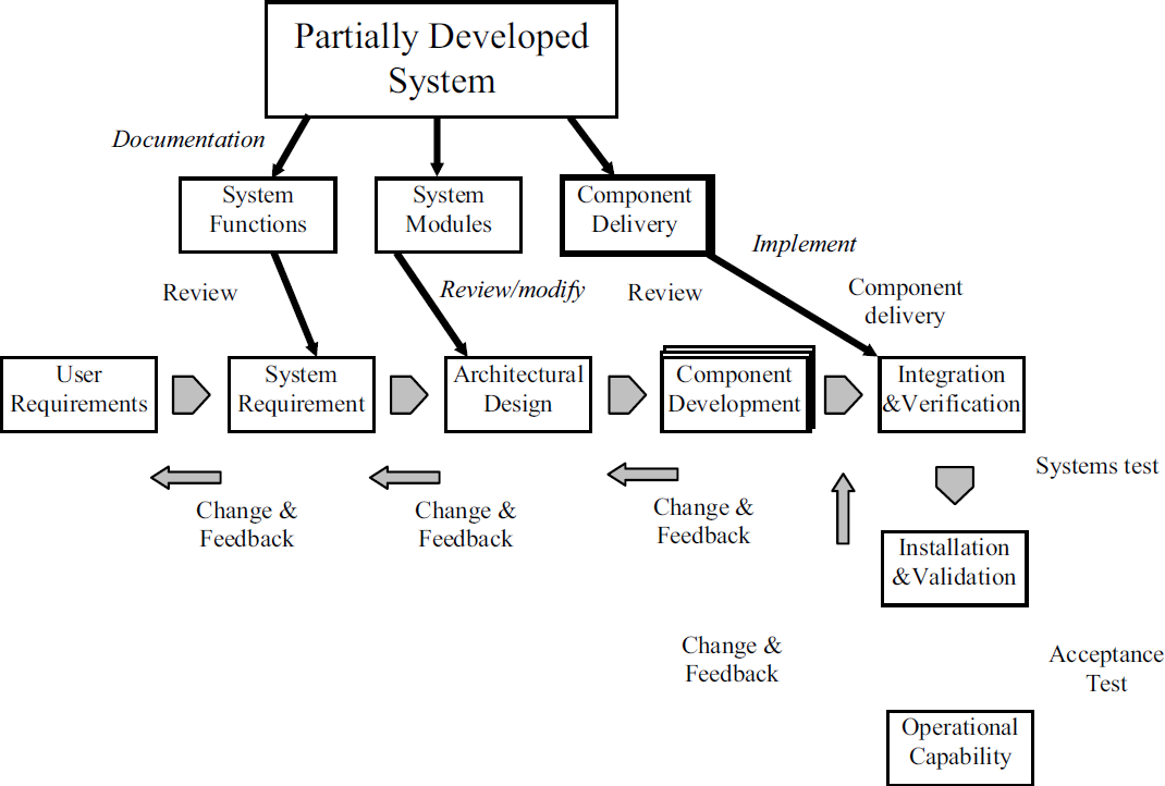
implementation of partially developed system into a new system
It is necessary to perform a complete analysis of the partially development system and identify the system functions, system architecture and the system components. The output from this analysis is a document that describes the system objectives and component functionality. It is possible to recall the format of the architectural design document herein as a model for the output from the partially developed system analysis in terms of:
Component behaviour Component functionality Component interfaces Component layout Dependency & required resources Test criteria
The partially developed system document can then be fed into to the system engineering process. Already developed components could be modified or integrated with the system according to the requirements of the architectural and the detailed designs. Afterward the process of the development returns to the normal steps for integration and verification up to the final operation step. The evolutionary development model enables the staged implementation of partially developed systems according to the needs of the development cycle. I.e. part of the system can be implemented in the first cycle as far as an operational system, and then the other part may be implemented later to suite the next stage of development and economic feasibility.
The SE development process described in section 4 is employed to develop the Starlifter robotic system. As the need analysis and the feasibility analysis is based on the use of Starlifter in concrete drilling and concrete sawing process, the starting point was to gather information from the end users as indicated in the user requirements. The following sections show the procedure used in implementing the development model.
The user requirements
In the current scenario the client (the contractor who wishes to introduce the new technology) raises the following issues:
The site is contaminated with lead because it was a store for batteries, which requires the avoidance of direct human intervention. The holes should be drilled as quickly as possible with reasonable accuracy using existing diamond core drills and other supporting equipment. Existing plunge saws should be used to accomplish the cutting process within a minimum time. Access constraints to the interior of the building exist. The finished product using the new system should be within standard tolerances The cost of the new system should be within the agreed limit. For the new system a user interface should be provided with all the required information concerning operation, safety and schedule. The system should comply with all standards of operation and codes of practice in this field. A compatible off-line system for task simulation, planning, scheduling, costing and report generation is required.
The site and safety engineers raise the following issues:
Marking the working area for drilling and concrete sawing should be done and approved prior to the actual operation. The supporting equipment such as power source, water source for drilling and sawing and the waste removal truck should be provided on schedule. The hazards involved in the system should be identified and a risk assessment should be prepared prior to implementation. Surveillance cameras are needed for operation and site supervision
The workers provide the following information for traditional methods:
The cutting tolerance should be within ±2 mm For a square opening, the number of holes required to insert the plunge saw is proportional to the size of the opening and the size of the sawing blade. For example, for a square opening of 1 m in side length and a 30 cm depth one hole in each side centre can be used with a blade diameter of 1 m. Anchors should be attached to hold and support the removed concrete block The drilling and sawing feed could be done manually or automatically Disposable protection suits should be used when working in a contaminated site Standard protection equipment is used when using the drilling and sawing rigs.
System requirements
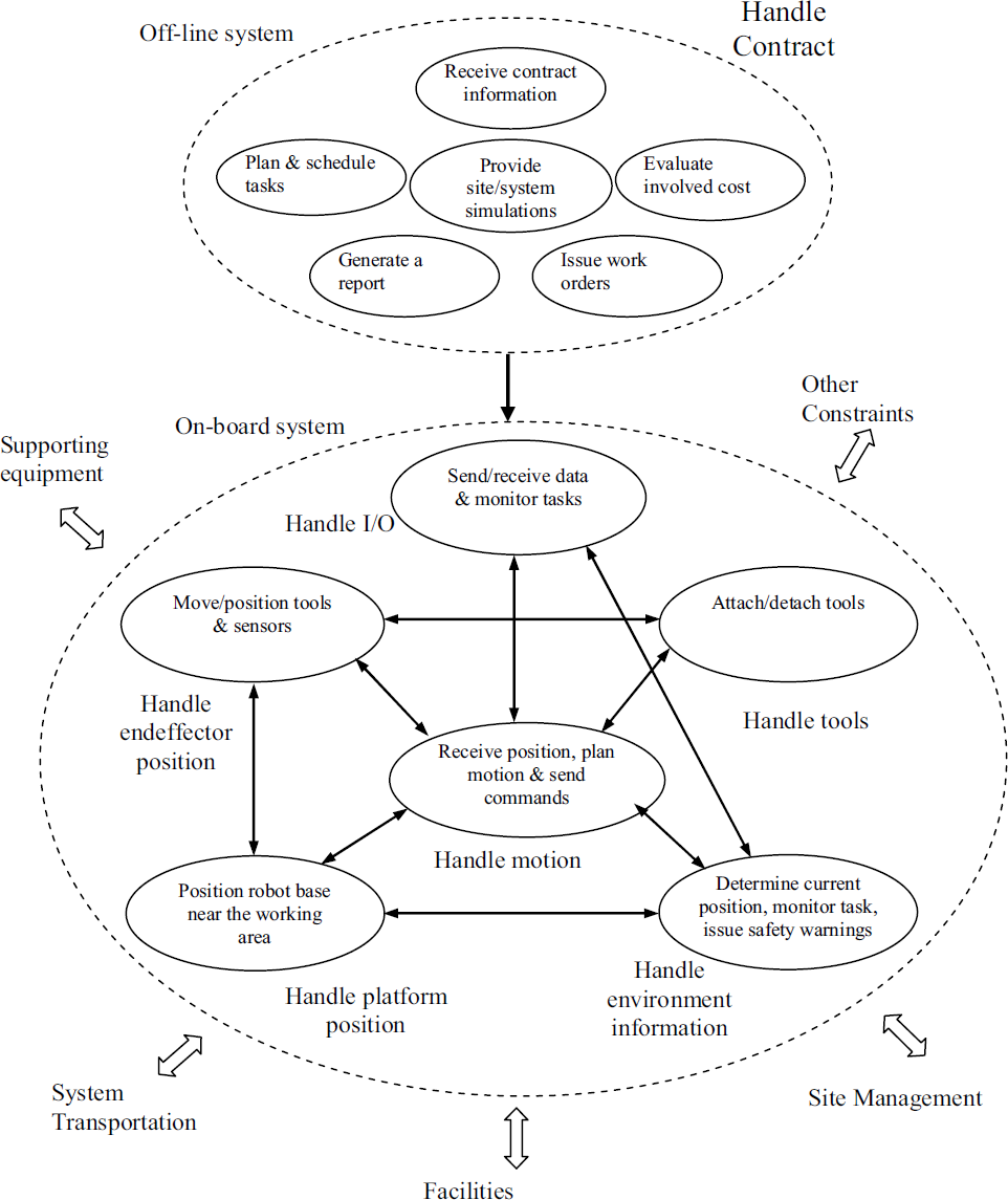
The user requirements capture process provided information regarding the operational environment as mentioned above the management decided to use robotic technology to avoid the risks involved from the safety point of view. It is now possible to identify the required system capabilities in terms of the user requirements. The user requirements can be translated into system requirements, which can be defined in terms of different functions. The main system is divided into two subsystems, the first is the off-line system and the second is the on-board system.
The main functions of the off-line system are:
Receiving the contract information Creating simulations for the system components and the working site Identifying tasks Planning tasks Preparing task schedules Evaluating the contract costs Generating a descriptive report for the whole contract including prices Reviewing the resources required Reviewing safety issues, codes of practice and regulations Arranging for tools and logistics dispatch Issuing working orders
The on-board system function is mainly divided into six functions; these functions collaborate to perform the main function. There are interdependencies between the systems involved in doing these separate functions. These functions can be decomposed as follows:
Handling input and output from and within the system
Receiving work issues and task details from the off-line system. Sending and receiving information from and to different components of the system. Monitoring the performance of the individual system components and assuring harmony. Task monitoring and task sequence control Handling platform position
Selecting the platform Moving the platform to a desired position Providing a stable position for the platform Handling other logistics Interacting with other functions Handling environment information
Monitoring the working area Checking for collisions in the working area Perceiving relative position and orientations w. r. t the working area Issuing safety warnings Interacting with other functions Handling motion
Receiving position information Sending signals for position modification Rectifying position Path planning Interacting with other functions Handle end-effector position
Receiving commands Handling tools Providing a stable platform for tools Providing resources for other functions Providing desired configurations Interacting with other functions Handling tools
Providing multiple tool docks Providing Stable platform for tools Providing easy engagement and disengagements of tools Sending tool status
A functional decomposition diagram, which includes the required system components that satisfy the user requirements, should be prepared alongside a scenario for the proposed task. The functional decomposition diagram and the system scenario illustrate the interrelationship between the system under development and external systems such as site management, facilities etc.
Architectural design
The architecture design concepts can be represented in three forms, all of which give increased understanding of the system under development. The three forms are: the system structure, the system behaviour and the system layout. As mentioned before, the system structure defines the major component organization and decomposition. The system behaviour defines the inherent dynamics in the system and shows how the system will behave during operation. Finally the system layout defines the physical interrelationship between the system components as well as the relative position of the components.
System structure
For a robotic system it is possible to define the major components based on the functional decomposition presented in the system requirements. It is however difficult to make a relative structural decomposition or a hierarchy of the major components because all of them are distinctive and cannot be subsystems of each other. The decomposition of each component can be done based on the sub-functions involved in the main function of the component. Fig. 7 shows the major components of the Starlifter robotic system structure. The major components are off-line simulation module, the user interface, the controller module, the sensing module, the manipulator & end-effector module and the tool-changing module.

The robotic system structure
The system behaviour can be identified at the top level as described in the operational scenario. The system behaviour model shown in Fig. 8 illustrates the top-level behaviour of the major components of the system. Clearer system behaviours may be illustrated by lower level subsystems, for example, communication behaviour in the controller module, where data is exchanged within the subsystem itself as well as between other subsystems in the architecture. Fig. 9 shows a behavioural model of the controller module.
Starlifter robotic system top level behavioural model
Top level behavioural model for the controller module
The top layout of the system is a direct interpretation of the physical component arrangement. These components are performing the main functions illustrated in the functional decomposition diagram and their behaviour is illustrated in the behavioural model. The on-board system layout is shown in Fig. 10
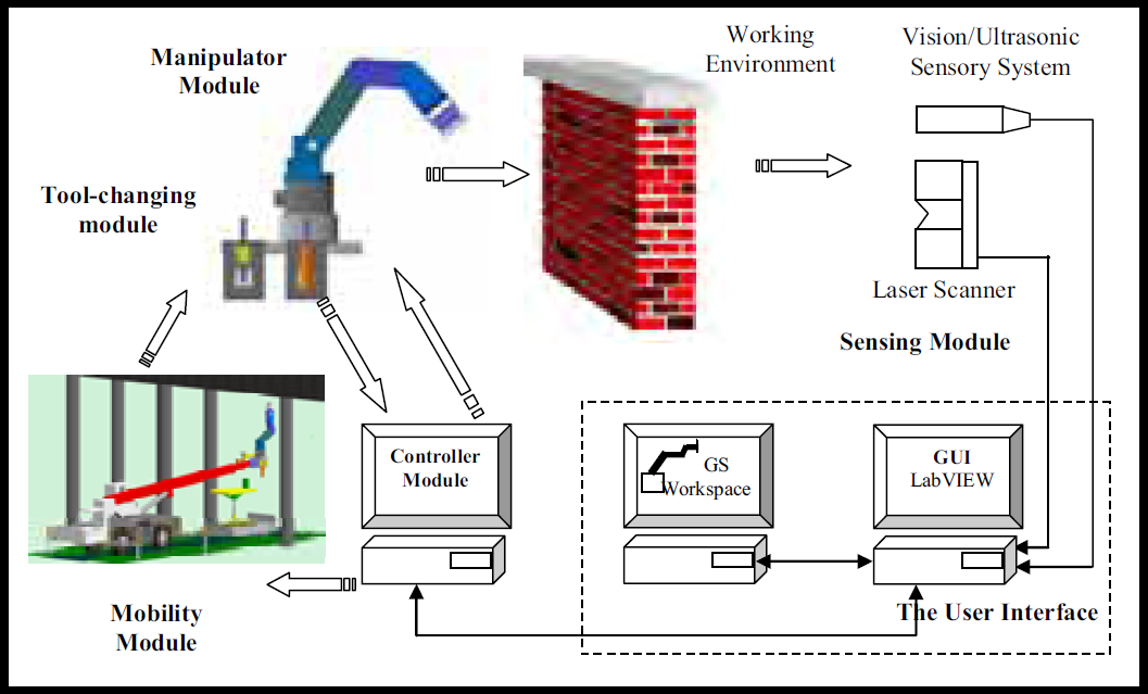
Starlifter robotic system on-board layout
The layout diagram shows some details of the final working system but the design details or types of interfaces are not specified. The major components in the above layout are the six modules already identified in the behavioural module but with some emphasis on the components used in the design. The selection of the above core technologies for this application is not an easy task. For research purposes it is necessary to investigate the new technology and to assess the suitability of this technology for construction applications.
The graphical simulation process of robots facilitates a fast and accurate validation of the resulting motion. The graphical simulation process is used extensively in industry to examine robot programs before downloading to the actual robots. The use of this method reduces the standstill time and increases productivity. The simulation tools are used to aid the choice of manipulator configuration and to test the usefulness of the robot by virtual scenarios.
In the present work, Workspace® robot simulation package is used in the simulation of robot, tools and the working environment see Fig. 11. The graphical simulation process of a robot mainly depends on the D-H parameters, Danivet-Hartenberg (1955), which can be derived by constructing a kinematical diagram of the robot.

Simulation of the Starlifter robot
The simulation process plays a major role in Starlifter development. The simulation process is used in the following areas:
System design Motion planning Environment modelling Task monitoring Cost estimation. Off-line programming
The design process includes testing the adaptability of off-the-shelf components and exploring possible modifications to existing components to suit the system under development. The following components are presented as examples of the use of simulation in the design process.
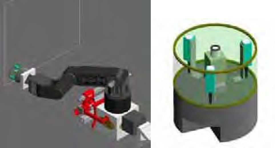
Automatic tool changer
As an essential part of the robotic process, the automatic tool changer is available as an off-the-shelf component with different sizes to suit different tools. The actual tool changer dock consists of two halves, one on the tool side and the other one on the tool holder side. The tool changer is currently pneumatically operated. It is intended to change it to a hydraulically operated one, which is consistent with the robot operation power source. There is a tool holder and a tool dock for each tool, in each dock there is a tool gripper, which holds or releases the tool whenever required. In the design of the tool changer two main issues are raised. The first issue is the tools arrangement and the second issue is the tool holder motion.
The tool arrangement design depends on the number of tools and the sequence of tool usage. It is required to put the tools in a confined space at the robot base to ease the motion of the robot base during positioning of the robot. There are two options concerning the motion design of the tool holder. The first one is to move the endeffector to a known position of the tool holder (The tool holder being fixed.) The second option is to move the tool holder inside the working envelope of the robot whenever it is required to change the tool. The second option provides a clear working envelope during task performance however a collision with the arm could occur if the motion is not accurately planned.
Mobility
The mobility module is concerned with positioning of the robot base in a relatively accurate place near the working area. The mobility module should provide a stable platform for the robot during task performance.
The required capability of the device to be used in robot positioning depends on the working area characteristics. For example, working underneath a bridge or in high places (free positioning) requires the use of a telescopic boom. While working inside rail tunnels requires the use of special truck. The simulation process helps the system designer to try different alternatives for the project.
An example for a mobility device working inside a rail tunnel is the SRS rail/road truck SRS, 2002, which can be used as a mobility device for the Starlifter robot which provides a stable platform for the robot as well as a safe platform for the robot operator. It is designed to work safely inside active tunnels while other trains move alongside. Fig. 12 shows different views of the truck carrying the robot. The simulation of the truck is drawn using the real dimensions.

The rail/road truck simulation
The proposed sensing strategy for Starlifter robot shows the need for a sensing head to be attached to the endeffector or to be placed in a suitable position that avoids collisions with the tools or the arm. The sensing head includes three types of sensor:
a vision sensor, which is a CCTV camera for in-situ monitoring of the working place, ultrasonic sensors for endeffector alignment to the working area, a rebar locator for reinforcements detection.
The sensing head can be attached to a tool changer dock if it is going to be attached to the endeffector. Fig. 13 shows a design for the sensing head that includes ultrasonic sensors and CCTV camera. This design makes it impossible to sense at the same time as operating the tools. It is however possible for the robot controller to store the sensing data and use it after detaching the sensing head. This design could be suitable for the rebar locator sensor in which the scanning process for steel reinforcement should be done before tool positioning. Several designs have been evaluated using the simulation package to achieve a suitable solution for the sensing head.
Sensing head simulation
The common use of the simulation process is for motion planning and checking paths for resolved motion. It is needed to identify the working envelope of the robot to position the robot inside its working envelope before attempting to plan the motion of the endeffector relative to the modelled environment. The identification of the working envelope enables the calculation of the maximum plan area that the endeffector can continuously scan. From the examination of the working envelope, the maximum vertical rectangular plan area that the robot can scan is about 5 m2 in free space. The calculation of the maximum scanning area provides information about the productivity of the robot in case it is used for other applications such as blasting and spraying. The simulation package can also calculate the optimum position of the robot relative to the modelled working area.
All planned motions of the robot can be recorded and viewed as video clips that can be passed to supervisors and customers for reviewing or presentation of the work. Workspace simulation package provides the facility of recording the planned motion in the form of track files which, with some manipulation, can be converted to a robot level language or as in case of the ATC controller user interface to task language files.
Environment modelling
The off-line programming process of construction tasks is required to be repeated for any change in the working environment or the characteristics of the processes involved. It is not feasible to start from scratch for every programming task i.e. to build a model for each task from scratch. For specific applications of the Starlifter robot it is recommended to build a simulation library that contains all the components involved in specific tasks. These components include the robot, tools, delivery vehicles, mobility devices and sensing head. In addition to these components, models for the common shapes of the working environments such as walls, floors, bridges, and tunnels. The use of ready-made simulations for these components accelerates the programming process. The simulation packages allow the implementation of the ready-made components in addition to the CAD drawings of the working environment. It is however necessary to convert the CAD drawings to a readable format that the simulation package can implement
Task monitoring
Task monitoring is performed in real time and involves the simulation package being connected to the actual robot using a suitable interface. This process, in combination with a CCTV camera, gives a clear image of the robot moving in the working environment.
New versions of simulation packages provide high-level graphics, which can simulate the actual world effectively. Some packages can provide kinematical and dynamic information of the simulated robot, which is very useful in the robot controller design.
Cost estimation
The graphical simulation of the robotic system components and the working environment provides excellent information that can be used in task cost calculations. Based on the tracks files created by the simulation process in addition to the fixed cost of the system components and overhead cost, a realistic cost can be calculated before the actual job is started. In the following section a detailed cost analysis of a task is presented.
In this study, a task time evaluation technique will be used to determine the time consumed by the simulated robot to perform a task. A delay time based on experimental work is then added to the simulated time to obtain the actual time that the robot takes to perform the same task in the real world. This delay time is site/task/robot dependent.
Four types of motion are considered based on those defined by Hass and Hsieh in 1993 as the elemental motions, which describe all the operations of a construction manipulator:
Platform Motion Gross Arm Motion Fine Arm Motion Endeffector Motion
Considering the fact that the simulation process does not take into account the effect of the environment on the robot performance (the simulated robot moves in an ideal environment with instant response to the required motion), the calculated time for each motion type should consider the delays generated due to the effect of the environment. For instance when using a telescopic boom to position the robot, the simulated boom does not consider lateral vibrations of the actual boom tip and the effect of friction and wind force on the time taken to reach the desired position. In addition there is the error due to human factors in operating the boom which are corrected by trial and error and which add additional time to the estimated time. Other delays could be generated due to the sensing & decision process and from force build-up time, especially for hydraulic robots.
The controller development
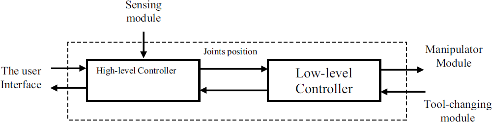
The robot controller can be considered as the brain of the robot, which is responsible for receiving and sending signals from and to the arm according to the demanded position and rate. As described in section 6., the preliminarily functional decomposition of the Starlifter controller module is divided into two main sub-modules, the high level controller and the low level controller as can be seen in Fig. 9 The high level controller or the kinematic controller can be considered to be a software based module while, the low level controller or the servo controller can be considered to be a hardware based module, however software is required to configure the low level controller and controller design implementation. The functional decomposition of the controller under development is basically derived from the current Starlifter controller which consists of the kinematic controller known as ATC and the existing servo controller developed by UK Robotics Ltd. It is hence required to re-engineer a new controller to enable the use of real-time sensors and other elements such as a link to the simulation package interface. The issue of using existing components of the current controller in the development of a new controller is considered here in which a detailed analysis of the current controller components is conducted to identify the main functions and the physical layout of the components.
The ATC controller cannot be used if any change is made to the servo level control. The reason behind this is the initialisation code of the ATC software, i.e. a message from the servo controller is sent to the ATC to confirm that the system is ready for connection before the ATC can start up. Currently there is no access to the code to modify this confirmation.
In these circumstances the following components are identified for development:
A kinematics controller (high-level controller) to replace the ATC controller A low level controller based on the existing components
The high level controller
The main reason of developing a new controller for Starlifter robot is the current difficulty in accessing or modifying the existing kinematics code associated with the operation of the ATC controller. The starting point in developing a new controller is establishing the main functions of the controller, which in fact, will resemble the functions that the existing ATC performs. Other functions can then be added to develop a more advanced controller it is more convenient to use an abbreviated name for the new controller, which will be called SICO (Starlifter Interface Controller Operator). The main functions of the SICO-HL can be summarised in the following points
Teleoperational control
This function provides a facility for the operator to move the robot using joysticks. This mode of operation requires the presence of a human in the loop at all times and it also provides control of the individual joints as well as resolved motion.
Pre-programmed motion control
This facility provides advanced control of the robot motion and it can be considered to constitute real automation of the robot task although a human is still in the loop, but with minimum intervention. Pre-programmed motion can either be derived using a simulation package such as Workspace which is then converted to a format that the robot controller can understand, or it can be programmed directly using a special editor built into the controller software, as in the case of the task language editor in the ATC controller.
User data input/output and visualisation
This facility is a basic facility, which is required to input a desired robot position or to monitor the current robot position in terms of the joint angles of the Cartesian position of the end effector. It is also useful to issue warnings for violation of limits at the joints or the robot envelope
Sensor data fusion
This is the added value to the system which provides more advanced control facility, which could lead ultimately to a partially autonomous robot. This requires suitable sensors for robot positioning, end effector adjustment and task area monitoring facilities. In fact it is the main aim of the current research project to add intelligence to the current robot. Developing SICO with these facilities could open the door for future implementation of sensors.
Robot kinematics
Forward kinematics
Forward kinematics describes the Cartesian position and orientation of the end-effector in terms of the manipulator joints angles. To solve the problem of forward kinematics, a simple algorithm presented by Mckerrow in 1991 can be used. However it is necessary to define several terms, which can help in solving the problem of forward kinematics. The first term is the general transformation matrix. This matrix relates the end-effector position and orientation in relation to the base coordinate system; this matrix can be defined as:

Where:


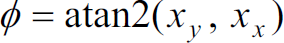
The end-effector orientation angles, (φ, θ, ψ) can be calculated in terms of the above elements of the homogeneous transformation matrix using the atan2 (–) function which determines the angle in its appropriate quarter. In the actual calculation to obtain numerical results to verify the correctness of the forward kinematics model presented above, the MATLAB atan2 function is used.


The zero position of the Starlifter robot, i.e. at 1 = 2 = 3 = 4 = 5 = 6 = 0, the end-effector position in mm and orientation in degrees calculated by the above formulation are:

This is consistent with the simulation results and the actual robot position if we take into account the same reference or the same base coordinates. Other tests were made to compare the forward kinematics model with the actual robot. Good consistency in position and orientation were obtained.
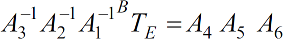
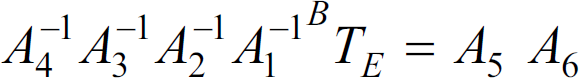
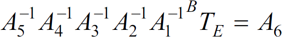
The inverse kinematics problem deals with finding values for the joints variables for a given Cartesian position and orientation of the end-effector. The solution of the inverse kinematics problem is called the arm solution, which can be found from the arm transform using the inverse kinematics heuristic, Mckerrow 1991. This heuristic is a method to find a solution but is not sometimes fails to converge on a solution. An algorithm developed by Mckerrow 1991 to solve the problem of inverse kinematics is used in the present analysis. The basic idea of this algorithm is to equate the general transformation matrix to the manipulator matrix and to look at the correspondent elements, which, contain one joint variable, or two elements, which could lead to one joint variable. This procedure can be repeated for different combinations of the transformation matrices. This procedure produces six equations as follows:


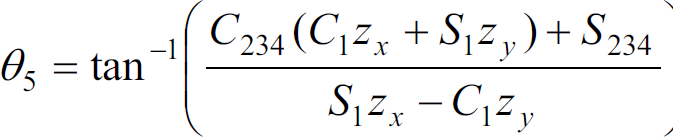
By equating the corresponding elements in each side of the equation and simplifying Paul (1981). This yields the joints angles as follows:


Where θ234 = (θ2 + θ3 + θA). Having got the value of θ234, the value of any angle of the three can be obtained once an expression is obtained for the other two angles.


Now the value of θ4 can be calculated as follows:


Having obtained the values of the six joints angles independently, a closed form solution for the inverse kinematics problem is obtained. It is however advantageous to put limits on extreme values for angles such as zero and 90 and 180 degrees to avoid overflow in the program by dividing by zero. These limits will generate an accumulate error about 0.1 degree which is acceptable.
The trajectory generation algorithm used in the current work is based on the work of Paul (1981). Fig. 14 shows the trajectories in joint and Cartesian spaces for arbitrary motion from point to point.

Trajectories generation in Cartesian and joints spaces for arbitrary Cartesian positions
The kinematics controller is a software-based module. The efficiency of the data flow between its components is of great importance owing to the criticality of the module. The behavioural model in Fig. 15 shows the interrelationship between the module components in terms of the behaviour model shown in Fig. 9. The behavioural model allows for the division of the kinematics controller into five components as follows:

Kinematics controller layout
This component represents the interfaces to the input devices such as joysticks and other interfaces such as the simulated robot and sensors.
Demand
This sub-module deals with the demanded values of variables and rates in joint space and Cartesian space
Processing
This sub-module deals with processing the input variable and rates for conversion into interchangeable forms. It also deals with trajectories generation in joint space and Cartesian space. Other functions include singularities detection and issuing warnings for exceeding limits or ranges.
Output and warnings
In this sub-module, values for the joint variables, Cartesian variables and rates are monitored and warnings are output to the user.
Implementation
This part deals with the low-level controller interface in which, data in the form of demanded joints variables and rates are passed to the low-level controller and the current joint variables fed-back to the user interface.
Low-level controller
Up to this stage, the high level controller performs all the mathematical operations to assign the joints angles which are needed to move the robot end-effector to a desired position defined by an angular or Cartesian position. The low level controller receives the demanded joints angles from the high-level controller and sends signals to the robot valves to move the robot to the desired position in a well controlled motion. The current Starlifter low-level controller design is basically a standard PID controller or literally a PI controller based on independent joint control. The Starlifter Low-level controller SICO-LL is designed to replace the current servo controller. Some changes have been introduced to the original controller layout and components to allow interfacing with the new high-level controller and the new LabVIEW programming environment. These changes allow on-line modelling of the robot and changing the controller gains. A LabVIEW user interface has been developed to interface the hardware components illustrated in the controller layout.
The fundamental functions of the SICO-LL controller are:
Sending signals to the joints valves Receiving the instantaneous joints positions.
These fundamental functions can be replaced by four main functions as follows:
The MOOG valve interface Internal sensor interface (Resolvers) Controller design implementation The High-level controller interface
The controller design implementation
This is the heart of the controller. This function is decomposed into three serial steps namely:
Dynamic modelling Controller design Design implementation
The SICO-LL control provides facilities to accomplish the above-mentioned steps. The following section describes the steps of this function applied to Joint (1) of the Starlifter robot with some theoretical background of the controller design philosophy.
Starlifter dynamical modelling
The transfer function of the Starlifter robot which, represents the system behaviour, can be obtained by using data based modelling techniques. One of the successful techniques is that developed by Young et al (1996) which has found a wide range of applications including heavy machinery, Dixon et al (1997), intelligent excavator, Gu et al, (2004) and environment related applications Lee et al (1998) and Taylor et al (1998). The system identification toolbox of MATLAB can be used in conjunction with the CAPTAIN toolbox developed by Young et al (2003) to obtain the transfer function of the robot in discrete time. The base for the data-based modelling technique is to collect information about the behaviour of the robot as a result of varying the input signals to the robot valves i.e. to relate the input u, (Voltage) to the output y (the joint position θ). Several tests have been conducted to evaluate the transfer function of the Starlifter robot joint (1). Owing to maintenance problems, the work couldn't be completed on all of the joints or implemented in the controller in its final form. The work presented here is to illustrate the applicability of data-based modelling and controller design using the Proportional-Integral-Plus (PIP) control philosophy.
Data collection and analysis
A series of planned experiments were carried out on the Starlifter joint (1) to produce input-output time series data relating the angular position of joint (1) and the valve input voltage. Fig. 16 shows the variation of the angular position of joint (1) with the input voltage to the joint valve. Two important observations can be extracted from this figure; the first observation is the linear variation of the joint angle for constant input voltage. The second observation is the sampling rate of the resolver which is very low for a responsive dynamic system such as a robot. The reason behind this slow sampling rate is the double serial readings of the resolver data. The resolver signal is read through a resolver to digital converter and then transmitted to the serial port of the servo-level PC and then this signal is transmitted again to the serial port of the SICO PC in which the signal is processed again and directed to the controller GUI.

Variation of the angular position of joint (1) with the input voltage, the input voltage varies in amplitude.
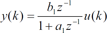
The Captain toolbox provides useful tools for system modelling and model validity parameters. The control strategy of the Starlifter robot is based on individual joint control in which it can be considered as single-input, u(k), single-output, y(k), (SISO), deterministic system, Young et al (1998). For a SISO system, the transfer function can be defined in terms of the sample number k as:

Where z−1 is the backward shift operator i.e. z−1 y(k) = y(k − 1) and the polynomials

Where a1,…,an and b1,…,bm are coefficients of system denominator and numerator polynomials, respectively.
The parameters of the model can be estimated directly using the simplified refined instrumental variable (SRIV) algorithm, Young (1985). In this algorithm, the YIC (Young Identification Criterion), coupled with the coefficient of determination,
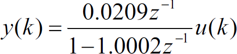
The Captain toolbox′ functions determine the following parameters:
Based on the data collected for joint (1), the transfer function can be written in the form:
The NMSS vector is given by:
For the first order system as joint (1) where n=1 and m=1 there are no input states in equation (7.75). The associated NMSS model can be defined accordingly as;

The control law can be written for joint (1) in the form:

Where f0 and kI, are the proportional and integral control gains respectively.
Using equation (35) which describes the closed loop transfer function the following form is given:

By converting the characteristics polynomial into z-operator yields;

The control structure represented by equation (36) is similar to the standard digital PI control however the manual tuning is replaced by a model-based optimal or pole placed design based on the identified model represented by equation (35). The pip function developed for the PIP control is used to calculate the gains kI and f0 for selected poles. Several gains are obtained for different poles placements. The values of the gains are examined using a MATLAB SIMULINK model developed for joint (1) as shown in Fig. 17. The best response has been obtained for kI = 9 and f0 = 40. The simulation output and the driving valve signal corresponding to a unit-step demand are illustrated in Fig. 18.

SIMULINK block diagram of the PIP control
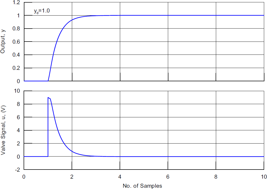
Simulation results
The proposed sensory system for the Starlifter robot is identified according to the available sensors. The functional decomposition of the sensory system proposed here is shown in Fig. 19. The sensory system functions identified below are:
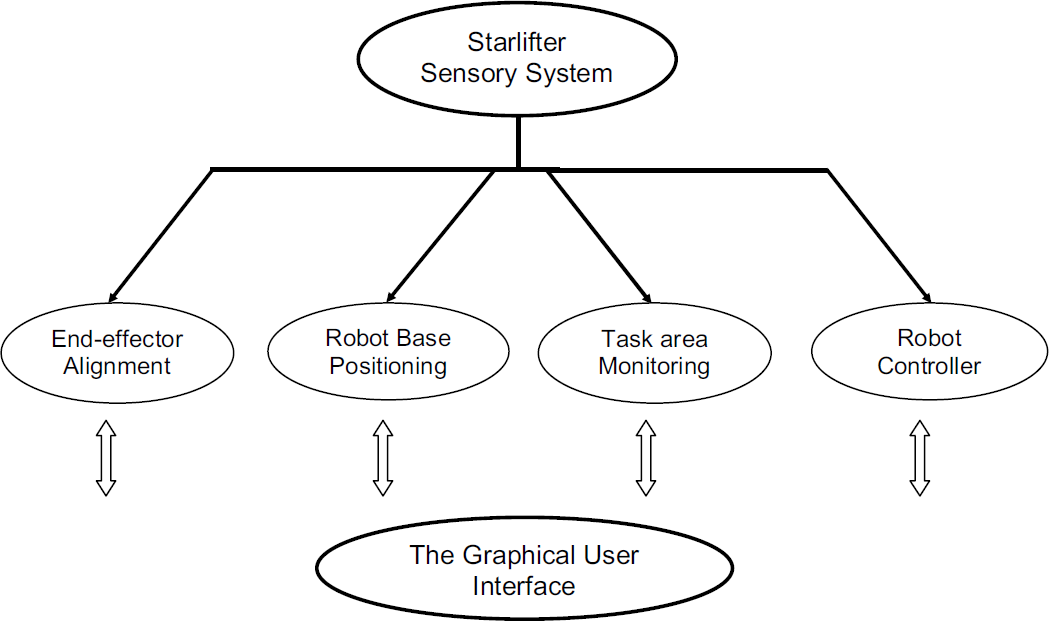
Main functional decomposition of the Starlifter sensory system module
End effector alignment using ultrasonic sensors
Robot base positioning using a laser scanner
Task area monitoring using a simple vision system
Most of the present work is conducted in order to achieve the following objectives:
Interface with the sensors Sensor data acquisition, processing and visualization Examination of the performance of the sensors for indoor and outdoor environments Validation of the sensor information Sensing strategy planning
The following sections describe in detail the laser scanner, the ultrasonic sensors and the video camera system.
The aim of using the laser scanner, in combination with a camera view, is to protect the robot and the working environment from collision during robot positioning-see Fig. 20, so that the robot can operate correctly within its working envelope. The camera view gives a 2D image of the working area and the laser scanner gives the third dimension as can be seen from Fig. 21.

The laser scanner sensing strategy

The laser scanner/camera assisted navigation
To illustrate the navigation strategy using the laser scanner, consider the following situation: the robot base is attached to the end of a telescopic boom to position the robot near its working area in a confined high place as seen from the views in Figs. 20 and 21. The laser scanner is attached to the robot base and is equipped with a video camera. The scenario of navigation can be summarised as follow:
The operator places the telescopic boom manually using their best judgement The sensory system is then switched on and a primary scanning of the surrounding area takes place. The operator then decides which direction the telescopic boom moves. By using the safety fields adjustment facility, the sensory system can then assist in navigation and the operator can relay on the warning issued by the system in case of possible collision.
The use of ultrasonic sensors for alignment of the end-effector is just a small part of a global sensing strategy concerning localisation of the robot relative to the working area. The position strategy includes:
Appropriate positioning of the robot base relative to the working area (Levelling) Determination of the robot base position relative to a reference position in the working area (Referencing), Positioning of the end-effector relative to the reference position. Auto alignment of the end-effector for correct operation of tools
The first and the second points are proposed to obtain a relation between the robot base coordinate system (xb, yb, zb) and the working area coordinate system (xw, yw, zw) (say artificial landmarks) –see Fig 22. Once the above relation has been established and the robot is in its working envelope, the end-effector can be positioned in the pre-planned position and orientation

Coordinate systems definition for the global strategy
Two sensing strategies were proposed by Pritschow et al (1996). The first sensing strategy utilizes a laser scanner and artificial landmarks for absolute positioning of the robotic platform. The second strategy utilizes a simple sensing technique using two distance sensors attached to the end-effector. This technique enables robot positioning relative to a known reference position, however it requires the working area to consist of two walls forming a corner. It is also required to perform several measurements at different positions to obtain accurate results.
In the current work, we are going to focus on a simple use of ultrasonic sensors for alignment of the end-effector perpendicular to the working surface to enable the accurate drilling of holes in concrete.
The current technique is valid provided that the following assumptions are met:
The robot base is positioned in a suitable position relative to the working area The end-effector position and orientation are known relative to the working area reference coordinates
The objective of using this technique is to ensure that the estimated orientation of the end-effector is accurate.
Four ultrasonic sensors are used for the alignment procedure –see Fig. 23. The four sensors are attached to a sensing head that can be used together with the automatic tool changer, i.e. the sensing head is first attached to the end-effector for alignment the sensing head can be then replaced automatically by the appropriate tool. Four distances can be measured at a single position using the ultrasonic sensors d1, d2, d3 and d4. Using the following relations the differential yaw and pitch angles can be calculated:
The differential pitch, dθ =

Sensors arrangement for the end-effector alignment
Where 2s is the length of the end-effector plate side, Δ1 and Δ2 are the difference in the sensors readings.
The values of the differential orientations dθ and dψ can be then used to adjust the end-effector orientation. It is more economical to use one sensor to perform this technique.
This can be done by taking a measurement at a specific position and then rotating the end-effector in increments of 90° and taking further measurements.
Several tests have been conducted to evaluate the sensor performance. A calibration test is carried out to verify the correctness of the sensor readings and a satisfactory calibration curve is obtained as shown in Fig. 24. Several readings were obtained for different positions of the object relative to the sensor- see Fig. 25. The sensor reading variation with time is shown in Fig. 26. From this figure, it is clear that, stable readings of the object position have been obtained The standard deviation of the readings ranging between 0 and 0.34 while the standard error of mean ranges from 0 to 0.004, the lowest values for the far objects.

Calibration curve for the UC3000 sensor
Sensor output
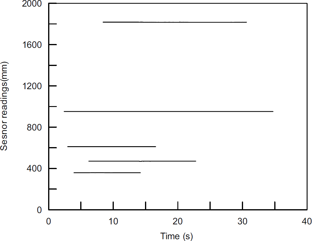
Variation of the UC3000 sensor readings with time
A simple dynamic test is carried out to obtain the sensor response to a moving object attached to a rail and falling freely under the action of its weight. The readings recorded are shown in Fig. 27 in which smooth variation of the object position with time is observed for the two test trials.

Sensor readings obtained for a moving object
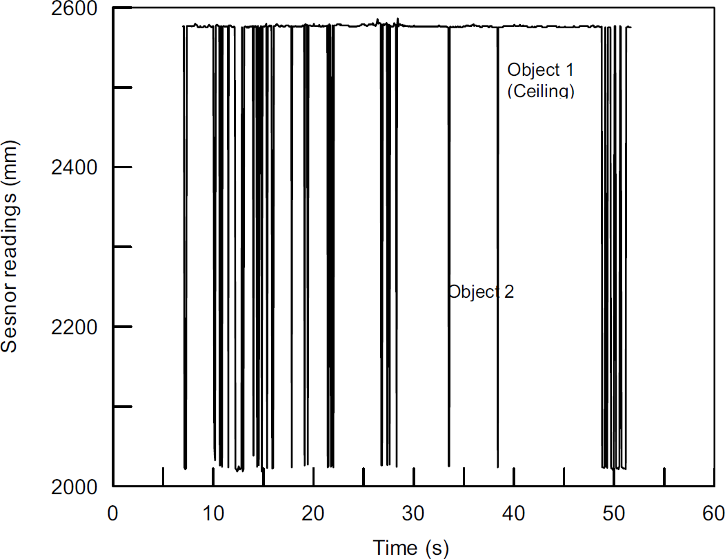
Excellent readings can be obtained from the sensors when objects are inside the sensor range cone with suitable environmental conditions.
Inclined objects more than ±17° give false or out of range response.
Multiple objects can be detected by the sensor and the response from the sensor is a fluctuating signal showing the possible position of the objects.
The sensor can be used as a navigation sensor as the end-effector approaches the target area
Generally speaking, the sensor shows good reliability for indoor conditions but more tests are required to examine the sensor performance for outdoor conditions.
Video cameras
Task monitoring by the system operator requires the use of video cameras placed at different locations in the working area. The use of video cameras could be for monitoring only or be useful in extracting environment features by using simple image processing facilities such as dimensioning of the work area. Video camera systems are available as off-the-shelf components however; the selection of a suitable camera for construction activity monitoring should consider the special nature of the working environment.
In the present work, the crucial issue in selection of a camera system is its interface with the system user interface, in addition to other factors related to the nature of the working environment which requires a durable and reliable camera system. An analogue video card is used in conjunction with an ordinary single focus camera to develop a monitoring system integrated with the sensory system discussed above. A stand alone user interface has been developed within LabVIEW to interface the video card. This user interface is based on the use of ActiveX components which includes several functions for video recording, frame grabbing in addition to image file manipulation functions. Image acquisition functions (IMAQ) built in LabVIEW are used for frame capturing, saving, and simple image processing such as zoom-in and zoom-out. The use of these functions can be extended to add other facilities such as on-screen measurements to extract dimensions and features of the working area.
As mentioned above, it is required to use more than one camera for task area monitoring. Analogue video cards provide an interface with only one camera per card which makes the system bulky. Firewire technology provides cards with multiple camera inputs, high image quality and easy interfacing. It is however expensive compared to the analogue cards.
The sensing head
The use of an ultrasonic sensor for end-effector alignment led to the development of a complete sensing head that can be temporarily installed at the end-effector during the alignment process and then uninstalled and placed in a safe and handy place on the mobile platform. This sensing head could include the following sensors:
Four ultrasonic sensors Video camera Rebar locator for reinforcement bars (if required)
The basic idea is to place the sensing head on one of the tool changer docks so that the end-effector can pick it up as required. Two sensing tasks are identified using the sensing head, firstly, alignment of the end-effector relative to the task area and secondly, scanning the task area for reinforcement using a rebar locator to avoid drilling it. The second sensing task is beyond the scope of the present work.
The sensing head is equipped with a video camera which is used to assist the ultrasonic sensors in extracting the working area features during the alignment process. This camera should have a wide focus lens to provide a bigger range than the ultrasonic sensors.–see Fig. 28.

The sensing head
Software development represents a substantial part of a robotic system development process, and the bulk of system development problems are often attributed to software problems. Most of the components involved in a robotic system require at least one piece of software for control or data transfer. The adoption of an off-the-shelf components strategy accelerates the hardware development process, however it can result in software problems associated with integration and interfacing. Alternatively, the use of specially developed hardware components takes into account interfaces and the final integration process, but development time and costs cannot be controlled. As a compromise, the problems associated with the use of off-the-shelf components can be reduced by the use of powerful software to handle interfacing problems.
In the present work, efforts have been made to achieve the objective of rapid software development. Three concepts are adopted here-in to achieve this objective. These concepts are architectural design, modularisation and prototyping. As mentioned in section 4 the principles of systems engineering allows for the use of these concepts, however they are used in a different way for software development.
Software development as a substantial part of the development process receives a package of requirements extracted from the system requirement document. This package can be then decomposed into modules and each module can follow the software development model presented by Seward and Zied 2004. However it is important to construct a global architectural design for all modules to give guidelines to the final integration process of the software package. Constructing the architectural design provides a clear image of the required software components facing the system developer. As can be seen from this architecture different components and interfaces are used to satisfy the system requirements. Some components come with service software, which needs modification, or adaptation and others require the development of new software. Decomposition of the component software into modules allows individual testing for functionality. This decomposition eases the development process but it puts much load on the integration process.
The use of graphical programming allows for the application of the above-mentioned concepts. Graphical programming is modular in nature, which in turn allows for building a hierarchy of the developed software, which represents the initial decomposition illustrated in the global architectural design. It also allows the building of applications from ready-made components that can be used to verify the functionality of a program i.e. building a prototype. However, this prototype can be reused in the final software development.
Designing an attractive functional graphical user interface (GUI) adds extra value to the software from the user point of view and graphical programming shows great capabilities in this regard. Using graphical programming can also satisfy other concerns such as keeping control of the development time and costs.
The detailed archtecture of the on-board system and the off-line simulation were presented in previous work, Seward and Zied 2004.
According the software architecture for the Starlifter system, the on-board system software components such as the robot controller and external sensors were developed as well as for the off-line simulation system.
Fig. 29 & 30 show the front panel for Starlifter robot controller and external sensors GUI integrated front panel.

Starlifter controller GUI with Workspace simulation package interface
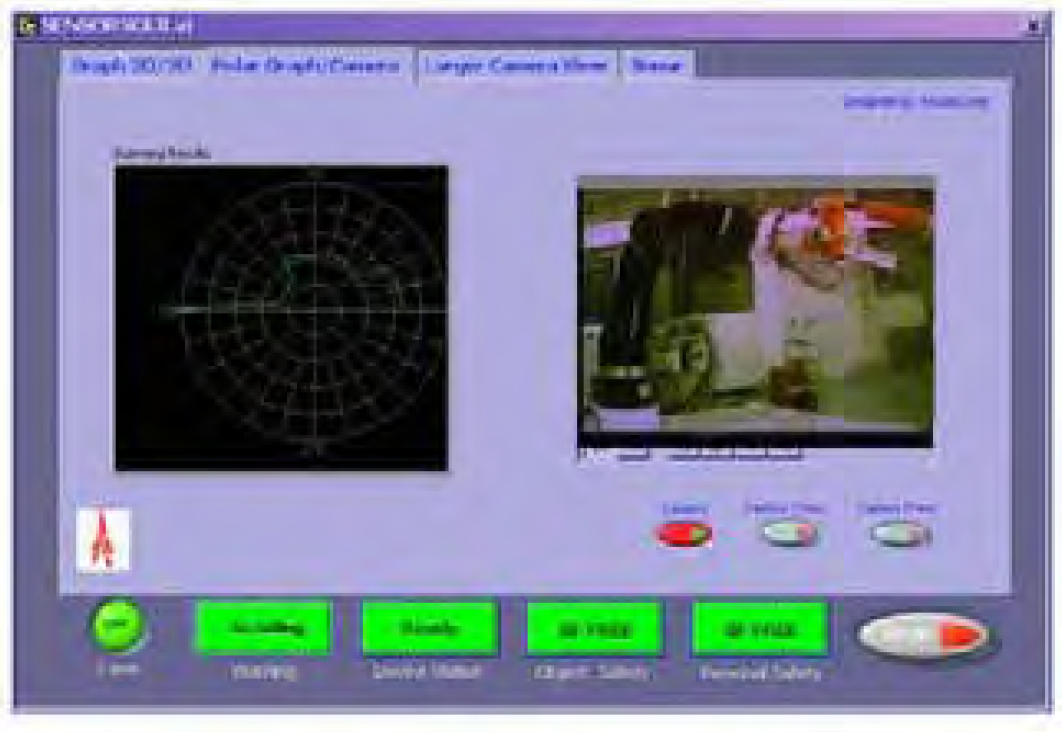
Starlifter external sensor intgrated GUI
Integration of different software components represents a substantial part of the software development process. However, the use of LabVIEW makes the integration process easier when used in conjunction with the architectural design explained previously. A major step that should be done before the integration process starts is software components testing. Testing and verification at the lowest level is the most feasible because it avoids accumulative errors Stevens et al (1998). Graphical programming provides facilities for easy integration such as polymorphism in data types, which enables the handling of several data types within a single VI without the need for data type declaration.
The developed components developed so far were individually tested for functionality and performance. Integration of the system components is performed through software. For example, external sensors are integrated in one module and test for functionality. The intgration of the other components can be done in the same way. This method will be verified by field tests of the integrated system.
Conclusions
This work focuses on the development of processes and practices for robotic systems for construction activates where human intervention is required to be minimized. Safety issues alert decision-makers to investigate the feasibility of using robotic systems for such environments to reduce hazard risks. The nature of construction sites and the nature of tasks involved in construction activities justifies these sites being considered as hazardous environments. Although strategic research on the use of robots in the construction industry has been underway for some time, little has been actually implemented owing to several barriers. These barriers come from firstly, the lack of feasibility analyses which justify the use of robots in the construction industry and secondly, the lack of methodologies and tools for rapid development of sophisticated robotic systems required for handling construction tasks.
The major research questions addressed were: How can the use of advanced automation and robotics be justified for use in construction activities?
How can such systems be developed in a modular and economic fashion for a wide range of different applications?
How can such systems be properly incorporated into the business processes of construction companies?
Consequently two primary objectives are identified in the present work. The first objective is the investigation of the feasibility of using robots for construction activities. The second objective is concerned with the engineering of the development process for such robots.
For the first objective, a feasibility analysis model is designed and applied to particular case studies in order to justify the use of robots in those activities. The feasibility analysis model consists of stages which address the problem from different viewpoints. Through the different stages of the model several methodologies and tools are identified and used to accomplish the tasks involved in the feasibility analysis model.
The Starlifter robot, the first robot in the world especially designed for heavy tool deployment in hazardous environments, is used as a robotic automation solution for the case studies presented in this thesis. From the case studies presented in this work, the proposed model is found to be practical and comprehensive because it handles the feasibility analysis from different viewpoints using simple and systematic methodologies. More case studies and/or robotic systems are required to justify the robustness of the proposed model.
For the second objective, many development models are investigated prior to the selection of a suitable model for the development of robotic systems for construction activities. Principles of Systems Engineering are investigated and found to match the requirements for the development of robotic systems. One of the proposed development models is the sequential development model which is used as a basis for the Starlifter development process. Functional decomposition, modularisation and architectural design are useful concepts used in the present work for the development of the Starlifter robotic system components. A complete functional decomposition and architectural design of Starlifter is presented for both off-line and onboard systems.
A detailed explanation and discussion of the development process is presented for all systems.
Graphical simulation is used in many aspects of the development process such as system design and task cost estimation. Graphical programming was found to be an appropriate software development environment for construction robots. LabVIEW is selected as the core software development environment. Comprehensive software architecture is presented for both off-line and on-board systems. A detailed design of the system controller is presented for both the kinematics controller (high level) and the servo-level controller (Low level). A data-based modelling technique is used to model the robot joints for the low level control design. The Proportional-Integral-Plus (PIP) control philosophy is used to design the controller for one of the joints in order to demonstrate the applicability of this approach for dynamic systems. Three types of sensor are used for the system navigation, end-effector positioning and task area monitoring. A detailed explanation of the theory of operation, sensing strategy and interface techniques are presented for each sensor. Integration of the three sensors with the system user interface is presented in detail.
Footnotes
8. Acknowledgements
I would like to express my deepest thanks to Professor Derek Seward for his major contribution throughout this work. Special thanks to the managing director of Construction Robotics Ltd, Mr John Riehl for his contribution and sponsorship of this work.