
Abstract
This paper focuses on a mechanical regulator free and front- wheel drive bicycle robot. We present a scheme to achieve the robot's track-stand motion and circular motion under zero forward speed. In a situation where the robot's front-bar is locked at 90 degrees, a kinetic constraint about the rotating rate of the front-wheel and the yawing rate of the frame is derived. Using the constraint as a basis, we developed a simplified model of two independent velocities for the robot. The model suggests there is an under-actuated rolling angle in the system. Our control strategy originates from the under- actuated characteristics of the robot system. Concretely, we linearize the rolling angle of the frame and set the bicycle robot to regulate its tilting by rotating the front-wheel. In the track-stand motion, we control the position and the rotational rate of the front-wheel; but in the circular motion, only the rotational rate of the front-wheel is strictly regulated. Both simulations and physical experiments results show that our strategy is effective for achieving these two motions.
1. Introduction
The bicycle robot (or the riderless bicycle) is a naturally-unstable system and the primary obstacle for its functional realization is its unexpected falling over. Traditionally there are two means to keep a bicycle robot's balance.
The first one uses additional mechanisms to stabilize the bicycle robot's body, called a regulator-based mean. In [1], the researchers proposed an autonomous bicycle with two mechanical gyros. They believed when the gyros spun in opposite directions, their gyroscopic torque, due to the precession of the gyros, would counteract the destabilizing torque due to the gravity force. In [2], the researchers designed a movable load mass in their unmanned bicycle. They suggested a control strategy. If the bicycle fell left or right, by driving the load mass right or left correspondingly, the robot system can recover to upright travel because its gravity centre has been regulated by the load mass movement. Differing from the mass design in [2], the researchers in [3, 4] focused on a rotational pendulum balancer in their work. They insisted that, due to momentum conservation, the rotation of the balancer opposite to the tilting direction could generate a regulating torque to compensate for the falling torque induced by the gravity force. In [5–6], a prototype's ultra-low-speed standing is well performed. In [7], the researcher presented two symmetric mechanical regulators, namely a rotational bar and flywheel, to adjust his riderless bicycle's leaning angle. He suggested the advantage of his design: when the symmetric bar or flywheel rotated, the bicycle's mass distribution should not be changed, thus it would be easier for his system to maintain balance. In [8], the researchers also adopted a flywheel regulator in their design, but what amazed us is that they achieved their robot's stable balance in a physical experiment under zero velocity. The most exciting example of flywheel-based bicycle robot may be the Murata Boy robot in [9], because the robot can stand still, track a curve and climb a slope, as if by magic.
The second mean is a front-bar-based mean, which lacks any type of mechanical regulators and depends on the front-bar's steering to balance the whole bicycle body, see [10–16]. Particularly, in reference [15–16], based on a lot of physical experiments, the researchers argued that the front-bar's steering might be more efficient than mechanical regulators in maintaining the bicycle robots' balance. In [17], people concentrated on a riderless bicycle in high speed running. They presented the idea that the front-bar's turning would exert decisive impacts on the bicycle's ability to maintain balance. In [18–20], the researchers argued that the front-fork's turning can regulate the bicycle robot's leaning by state feedback and the turning magnitude depends on the robot's running velocity. In particular, in [18] a lower bound for bicycle's running velocity was derived. They stated that, as long as the bicycle robot ran faster than this bound, it can be easily stabilized. In [21–23], the researchers achieved their own robot prototype's balanced running in a short time by using only the front-bar's turning. In [24], the researchers spent a lot of effort on the self-stability issue for a riderless bicycle both in theoretical analyses and physical experiments. Their work focused on “passive stability”: their bicycle was not configured with any actuators (e.g., a motor), so it kept balance by the coupling dynamics of the body leaning to the handlebar steering under the condition that there is a proper forward speed (they described it as “an initial forward push” in their paper). The most significant contribution of their work is that they presented a revolutionary view that neither the gyroscopic precession of the front-wheel, nor the wheel contact trailing like a caster behind the steer axis is necessary for the self-stability of a riderless bicycle.
A deficiency in mechanical regulator-based bicycle robots is that the regulators may somewhat increase the complexity of the systems' mechanism and control, which disagrees with the original intention of a simple design for bicycle robots. Another disadvantage may be the lack of a fail-safe capability, i.e., if the extra regulators fail, the robots would be disabled from their normal work due to their over- dependence on the functional action of the regulators. While for the front-bar-based bicycle robots, the main problem may be that there is not sufficient evidence to prove this kind of bicycle can perform the same balanced motions as well as the regulator-based ones. At this time there are no research groups (using theoretical analysis or experiment) who have ever performed the track-stand motion and circular motion without the use of mechanical regulators when the bicycle robots runs at zero forward speed.
This paper deals with the track-stand and circular motions of a mechanical regulator-free bicycle robot when its steering is locked at 90 deg. In this situation, the bicycle is like an inverted pendulum with a moving base (a system of two degrees of freedom), where the base moves in a circle and the pendulum is balanced by the wheel's rotation. We give a simplified model and a model-based controller for the system's track-stand motion and circular motion. Both simulations and physical experiments are introduced to validate the feasibility of our control strategy.
Our work provides a robust evaluation of the self-balanced capability of the mechanical regulator-free bicycle robots when they run at zero forward speed. As an extension, the results can also improve the regulators fail-safe ability for regulator-based bicycle robots.
2. Dynamic model
Our work focuses on a front-wheel drive robotic bicycle, which does not contain mechanical regulators. The target system and its kinematic relationship are shown in Fig. 1.

Prototype and its schematic diagram of a front-wheel drive bicycle robot, which is free of mechanical regulators. (a) Experimental prototype configuration. (b) Schematic diagram and coordinate settings of the bicycle robot.
We focus on the robot's track-stand and circular motions under zero forward speed, so we only consider the case that the front-bar is locked at 90 degrees. Figure 1(b) illustrates the Cartesian coordinates of the bicycle robot:
O –
We suppose the bicycle robot runs on a level ground, thus the frame's angular velocity vector can be given as
As shown in Fig.1(b), plane

The front-wheel is assumed to run on the ground without slipping, so the velocity of O4 is given as υB4 = –
The system's kinetic energy Ek can be divided into two parts: Ek1 and Ek2, which are represented as

where
In the previous analysis, we stated that q̇1 is a function of q̇2 and q̇6. For this reason, the system's total kinetic energy Ek can also be explicitly calculated from q̇2 and q̇6.
We assume the front-bar's turning cannot change the mass centre height of the system, so its potential energy is given as

where M1 denotes the total mass of the combination solid made of the frame, rear-wheel and front-bar.
By substituting the kinetic and potential energy into the Lagrange's equation, we can obtain the system's dynamics as

where

where Mij and Fi(i,j = 1,2) are the quantities which relate to system's kinetic parameters and

Equation (5) shows the bicycle robot is an under-actuated system, which only contains two independent velocities. Eq. (5) also demonstrates that the rolling angle of the frame is the under-actuated degree of freedom.
3. Controller for balanced motions
According to [25], one cannot linearize all the degrees of freedom of an under-actuated system just by state feedback, so we use partial feedback linearization to develop our controllers.
First, we solve the first formula of Eq. (5) to derive the expression of

where v is a newly introduced virtual control variable.
In the track-stand motion, we set

(k* is the state feedback coefficient). By setting variables ξ1=q2 – q2d, ξ2=q̇2 – q̇2d, η1 = q6 – q6d and η2 = q̇6 – q̇6d, we can get the system's affine equation from Eq. (5) as

where

Next, we discuss our control system's stability. From Eq. (7), we get its Jacobin matrix at the equilibrium point:

where w = M1gh/(Z4 + Z6) > 0.
The secular equation of the Jacobin matrix is described as

where w is the quantity, which relates to the system's physical parameters (mass, moment of inertia etc.) and the front-bar's fixed turning angle.
According to the algebraic stability criterion, the necessary and sufficient conditions of stability for the system of Eq. (7) can be described as that all the coefficients in Eq. (8) are positive and satisfy the relationship:

Obviously, the system's stability relates to the coefficients kd, kp, k1 k2 and the system physical parameters (w).
Figure 2 depicts the structure of the controller.

The structure of the controller for track-stand motion
In the circular motion, we should not regulate the front-wheel's angle position, so we set

Finally, we also formulated the necessary and sufficient condition of stability for a circular motion as

4. Control simulations
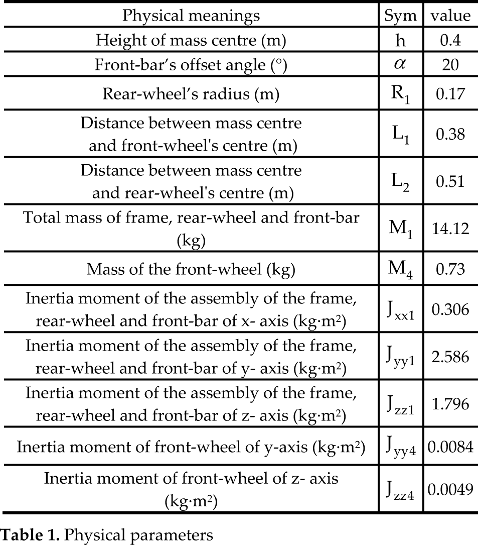
Table 1 shows the physical parameters that are used in our simulations. We obtain the parameters from the estimates of a virtual bicycle prototype in Solidworks rather than the parameter identification of our physical prototype, but they are still used in our following prototype experiments.
Physical parameters
We considered the necessary and sufficient conditions of stability of the controller in Eq. (9) and Eq. (11) and set the states feedback coefficients as:
Track-stand motion
Circular motion

The simulations were performed in Matlab/Simulink. At the beginning, we set the system leaning with an offset of 0.13 rad. Figure 3 shows the results of the two simulated experiments.

Results of the two simulated experiments. (a) Tilting angle of the frame and rotational angle of the front-wheel in track-stand motion. (b) Driving torque of the front-wheel in track-stand motion. (c) Tilting angle of the frame and rotational rate of the front-wheel in circular motion. (d) Driving torque and rotational angle of the front-wheel in circular motion.
From Fig 3 we have:
Track-stand motion The bicycle is initially set to tilt at 0.13 rad. Under the regulation of the controller, the tilting decays exponentially, and after four seconds, it gets to and remains in an upright position of 0 rad (Fig.3(a)). The front-wheel runs quickly to the position of 4.1 rad within 0.4 seconds of the beginning, and then smoothly back down to its initial position of 0 rad. The driving toque of the front-wheel also exponentially decreases with the maximum starting value of 14.63 N-m (Fig.3(b)), which is accessible for a normal DC motor. Circular motion The bicycle is also initially set to tilt at 0.13 rad. When the controller acts, the tilting begins exponentially decaying, and two seconds later, it converges to the anticipated 0.034 rad (Fig.3 (c)). At the beginning, the front-wheel runs quickly with a rotational rate of 13 rad/s. After two seconds, the rotational rate decays to the pre-set 9.42 rad/s. The maximum front-wheel driving torque is 7.5 N·m (Fig.3(d)). This torque can easily be provided by a normal DC motor.
In conclusion, the two simulated experiments validate the effectiveness of our control strategy.
5. Prototype experiments
A DSP-based prototype, called BYBR-I, is developed with 1.2m length, 0.7cm height and 23kg weight. Figure 4 depicts the hardware configuration of its control system.
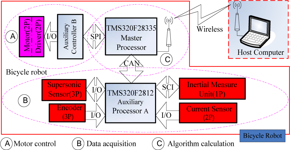
Configuration of the autonomous driving system
The developed prototype primarily consists of five parts:
Control unit (DSP + sensors) Communication unit (wireless modules) Support (aluminium alloy + steel) Actuation unit (DC servomotors) Accessories (batteries, auxiliary wheels)
The prototype is compact, thus the DSP-based control board, the wireless module, most of the sensory devices and the batteries are all attached to the prototype's frame. Two DC servomotors are mounted on the front-wheel's joint and the front-bar's joint. Via gear reducers, the two motors can easily drive the front-wheel and front-bar. To prevent the robot from falling over and damaging the costly devices, a pair of auxiliary wheels are installed on the two sides of the robot, which are 15cm from the floor when it stands erectly.
We use two DSPs (TMS320F28335 and TMS320F2812) and a MCU (C8051F020) as the core controllers in our system. As for the sensors group, an IMU (Inertial Measure Unit) sensor and three encoders are used to detect the current posture and rotational rate of the system. In addition, a total of three supersonic sensors and a pair of current sensors are introduced for detecting extended obstacles and monitoring the motors' current, respectively. Since the bicycle robot may run quickly over a long distance on the ground, we use a pair of wireless modules to transmit the recent states and control data between the host computer and the bicycle robot. Among the short distance on-board microprocessors, we designed a CAN, SPI and SCI bus to exchange data.
In Fig. 4, we can see there are four CPUs in the control system. We divided the system into three hierarchies:
the first one is the host computer, which manages the strategic decision and monitors the robot's state. the second one is the two DSPs, which perform data acquisition and control algorithm calculation. The last one is the MCU, which deals with the two joint control motors.
The normal working procedure of the control system can be summarized in four steps:
Step 1: TMS320F28335 sends a requirement message of sensors data transmitting to TMS320F2812 Step 2: TMS320F2812 receives the requiring message and then returns the latest sensors data to F28335 Step 3: Based on the received data, TMS320F28335 calculates the controlled variables and then sends them to C8051F020. Furthermore, the controlled variables together with the sensors data are also transferred to the host computer. Step 4: C8051F020 generates driving signals according to the control quantities that drive the two motors
Our prototype experiments also use the estimated physical parameters shown in Table 1. In addition, using the tuned feedback coefficients in simulated experiments as the basis, we reset the control parameters as
Track-stand motion
Circular motion


The control sampling rate for our system is 30Hz.
Figure 5 - Figure 7 demonstrate the experimental results of the prototype's track-stand motion and circular motion.

Snapshot of the track-stand motion physical experiment

Snapshot of the circular motion physical experiment

Results of the two physical experiments. (a) Tilting angle of the frame and rotational angle of the front-wheel in track-stand motion. (b) Driving torque of the front-wheel in track-stand motion. (c) Tilting angle of the frame and rotational rate of the front-wheel in circular motion. (d) Driving torque and rotational angle of the front-wheel in circular motion.
From Fig. 5, we can see that the bicycle robot performs the track-stand motion for longer than 10 seconds.
Figure 6 shows the robot stably runs on a circle trajectory with a period of about 12 seconds.
As seen in Fig. 7(a), the front-wheel runs back and forth in a range of ±0.9 rad and in response, the frame swings left and right in a range of less than ±0.06 rad. Figure 7(b) shows that the driving toque of the front-wheel reaches 9 N·m at the beginning, and fluctuates around 0 N·m the rest of the time. Figure 7(c) indicates that the rotational rate of the front- wheel and the rolling angle of the frame quickly converge and stay within a small range of their individual value. Figure 7(d) shows that the driving toque of the front-wheel runs around 1.8 N·m rather than 0 N·m. This is due to the influences of the joint friction and the ground friction.
In summary, we believe that, with the proposed motion controllers, the target system achieves stable-balanced track- stand motion and circular motion under zero forward speed.
6. Conclusions and future work
The track-stand motion and circular motion are two kinds of special balanced motions for a mechanical regulator-free and front-wheel drive bicycle robot because there is no forward speed in the two cases. We present a simplified model and a model-based controller for the robot to realize the two motions. Our model can excellently symbolize the coupling dynamics of our target system with two independent angular velocities and an under-actuated degree of freedom. Our balanced controller is characterized with a simple structure so it can be easily used by our prototype's control system. Through simulations and physical experiments, we validated that our bicycle robot can successfully attain the two considered motions with the proposed controllers.
Our work re-enforces the concept that the bicycle robots can maintain balance without any mechanical regulators. In addition, our methods can be generalized for fault-tolerance control of the mechanical regulator-based bicycle robots when they suffer from regulator malfunction.
One limitation in our work is that most of the physical parameters used in our experiments, e.g., the mass and the moment of inertia, are obtained from estimations, therefore, it is difficult to choose suitable controller parameters even by referring to the derived theoretical stability conditions. For this reason, the development of a controller parameter's self- tuning strategy should be the next work to be considered.
Footnotes
7. Acknowledgements
Our work is funded by National Natural Science Foundation of China (Grant No. 61105103) and Beijing Natural Science Foundation (Grant No. 4132032). Additionally, we would like to express our appreciation to Dr. Yuan Song for the help with physical experiments.