
Abstract
The work of fitting ceiling boards is one of the hardest in carpentry, as it requires large muscular power. Hence there is a need to develop assisting apparatus for such work. In order to use this apparatus anywhere a wearable robot is the most suitable. As the robot must be autonomous and lightweight, a design requiring low power is proposed. A semi-active control method has been developed using springs, which requires low energy but satisfies the requirements of compliance and assistive force. In this paper several aspects of design, control and experiments of the developed prototype is explained. The experimental results prove that the robot reduces the muscular fatigue of carpentry worker by providing suitable assistive force.
Introduction
The work of fitting ceiling boards is one of the hardest jobs in carpentry and there has been a great need to reduce muscle fatigue of workers doing such jobs. Any effective solution has not been proposed yet and the voice of workers who need an assistive apparatus for such jobs is increasing year by year. One of the backgrounds is that the average age of population of a carpentry worker has been going up due to the impact of falling birthrate and an aging population. Since the muscle power of a worker decreases due to age, the muscle fatigue of workers increases. Several apparatus for helping workers already exist, but most of them cannot be used in messy construction sites. Therefore, the need for developing assistive apparatus in the form of a wearable robot is of great importance. The reason why this type of carpentry work is harder than other jobs is because there are several phases in one task as shown in Fig. 1.
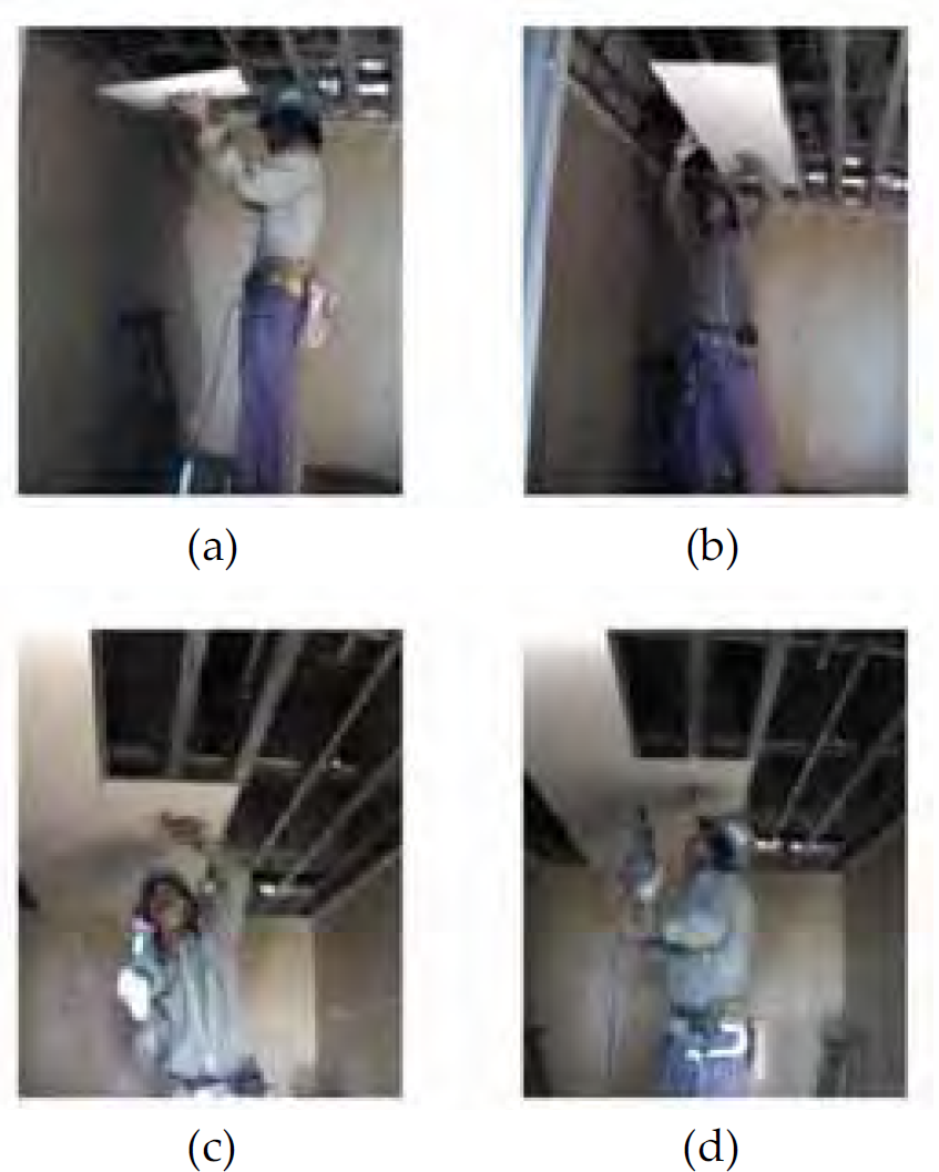
(a)-(d) Different phase of the task.
Lifting up of board
Setting the board with both hands in proper plane
Support the board with one hand and fix the screw
Leave the board and fix the screw with one hand
In particular, phases (b) and (c) are the hardest of the four phases. Workers have to support a board overhead and maintain the supporting posture for a long time. The muscles become tired as the worker perform this task repeatedly without any rest. A robotic device for assisting these phases can reduce the workers muscle fatigue efficiently. It is important that phase (a) requires dynamic motion and (d) needs a quick and accurate positioning. It is necessary to make all these motions possible when workers use the robot. These observations led us to decide the essential requirements: we have to make a wearable robot that is specialized for a man supporting boards and it should allow for precise motion.
Previous work
A number of different methods have been proposed in developing assistive robots or apparatuses in the last few years. Several wearable robots are shown in (Kawamoto, H. & Sankai, Y., 2004) and (Ishida, Y. & Kobayashi, H. et al., 2002). On the other hand non-wearable device are shown in (Herder, J. L. 2005) and (Namatame, K. & Morita, T., 2004). The main aim of the non-wearable devices is assisting patients who have neuromuscular diseases and cannot move their arms using their own muscular power. These apparatuses are normally fixed on the side of wheelchairs and support the patient's arm. In particular, Herder's method (shown in Fig. 2) is interesting since the end effecter of apparatus fits only a forearm and can deliver the force with support bracket. Comfort to wear is one of the important factors of wearable robot. This device does not cover the large area including elbow and shoulder, so that small fitting area contributes to good comfort. In addition, it generates a constant upward force when patients move their arms by using tension springs. As a spring has the property of energy conservation, electric power is not required, and only fine-tuning of the spring constant is required. Although this method has several benefits, it is not possible to change the applied force easily. Because of the benefits, it will be possible to be the best assistive device for the carpentry work by combining devices that adjust the equilibrium positions of the spring elements in real time to generate proper assistive force.
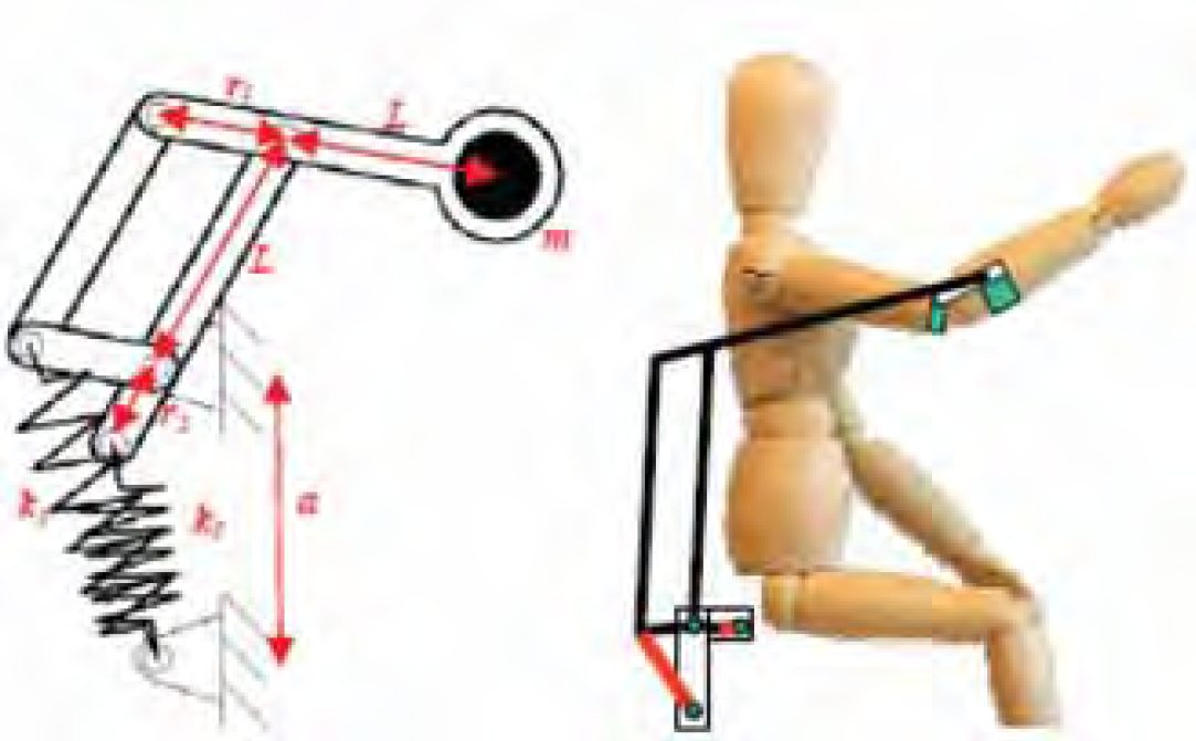
ARMON (Herder, J. L. 2005)
In order to tap the benefits using of springs and to change the generated force easily, we propose a semi-active method of control. One of the characteristics of the proposed method is the use of two springs. In the two previous works (Herder, J. L. 2005) and (Namatame, K. et al., 2004)), all springs are tension springs, but our model uses a tension and a compression spring. When a compression spring (free length = L [m], spring constant = kc [N/mm]) set at (0, 0) and tension spring (free length = 0 [m], spring constant = kt [N/mm]) set at (0, yt) are bonded at the free end, the resultant force is expressed as follows:


These equations show that when r (length from origin to bonded point) is as given in Eq. (3), the resultant upward force is constant where Ty = kcyt, and horizon direction resultant force is zero where Tx = 0.

Due to this, the resultant force only acts towards the upper side (Fig. 3). Although this is true only when r is as given in Eq. (3), the resultant forces mainly acts upward as shown in fig. 4. This force is applied to the forearm and it is used for reducing the loading force on the arm due to the boards.
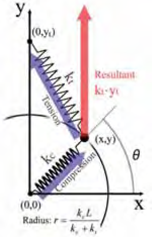
Spring force
Calculated resultant Force
In order to apply this force to forearm, a pantograph mechanism is used. This mechanism changes the force based on a magnification ratio. As shown in Fig. 5 the force input at point A is output as a force at point B in the rate of 1/Lpan in magnitude. In our method, the forces generated by the springs is input at point A and delivered to the forearm at point B.

Pantograph
In addition to these, it is necessary to change the assist force in order to assist workers who have various weights in their tasks. Equation (2) shows that when we want to change Ty we have to adjust the height of the tension spring yt, because the other parameter does not change. Therefore, a semi-active device is added as shown in Fig. 6. The semi-active device consists of a motor, a ball screw, a linear motion guide and a tension spring the end of which is bonded on the base. In order to change the spring height (yt) the motor is activated to move the ball screw. On the contrary, when we want to maintain the force, we have to stop the motor and this does not require high power. In the support posture, the supporting force needed is constant, and using the semi-active device requires low energy consumption. In addition, the usage of springs has another benefit as it provides compliance. This compliance gives the workers good mobility that is necessary for accurate and delicate tasks like, setting the boards in proper position and fixing the screw.
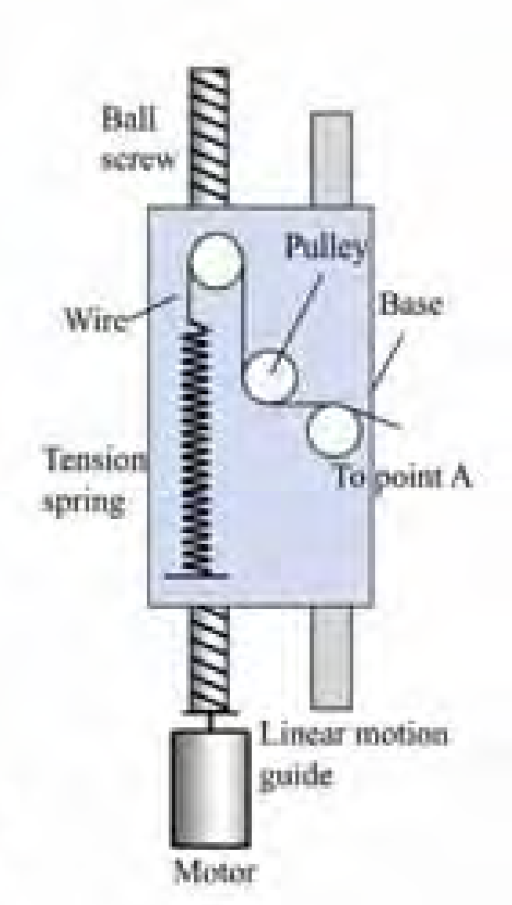
Semi-active device
Figure 7 and 8 show the basic design of the wearable robot and the first prototype respectively.

Basic design of the wearable robot

Prototype
Weight
We decide the size of robot considering the average height of Japanese men. Table 1 lists the specifications of some parts of the developed prototype. Although the total mass is a little heavy, there exist possibilities to reduce the weight of the robot and to make it much smaller. We developed the prototype which gives priority to strength because the main aim of this study is to confirm the effectiveness of the robot. Thus, we have not optimized the design of the frame with respect to the tradeoff between the weight and strength. As a future work, we can develop lighter and smaller one by designing all parts in suitable forms for the robot and by choosing proper material.
Detail of parts

Detail of parts
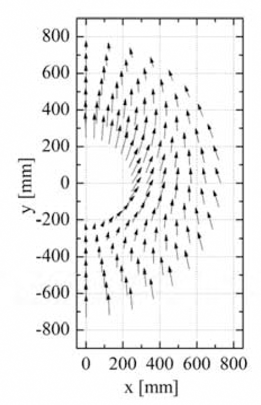
We calculated a vector diagram influenced by the weight of pantograph (shown in Fig. 9), and the generated force at point B in Fig. 9 is measured and compared with the calculated force. This contour shows the magnitude of vectors if yt = 210 [mm]. Some examples of the force are shown in Table 2. The design was successful because the force values are nearly the same. It is assumed that small differences in each value are due to a little difference in position when we measured or due to friction between metals and wires. The maximum Force to which this device can be output is 45 [N].

Vector diagram and contour (Contour unit is N)
Calculated and measured force

The adjustment speed of the force was also measured. The maximal adjusting force per second is 11.24 [N/s]. If we want to make this a little faster, we can choose a more powerful motor.
Energy consumption was also checked. When the motor is stopped, it needs an average of 3.75 [W]. If we move the base up and down, the motor needs 28.8 [W] and 1.2 [W] respectively. As an example, the base is moved up three seconds and kept 24 seconds there. After that, in another three seconds the base is moved down. In this case, the average electricity consumption is 6 [W]. This clearly shows that this robot needs a small amount of energy consumption and hence does not need a big battery.
Mobility
Operation area of a subject using the wearable robot was observed by using motion capture camera. We set two measured points (color balls) at shoulder and wrist (shown in Fig. 10-(a)). The position of a shoulder was set as the origin and we measured the movable range of wrist. The experimental result is shown in Fig. 10-(i), (ii), (iii), (iv). The red dots are the position of the wrist while using a robot and the black dots are the position of the wrist without using robot. Each figure shows the movable range in x-y plane, y-z plane, x-z plane and perspective view (these axes are defined as shown in Fig. 10-(a).). These figures show that the red dots area covers almost same area of the black dots except rear area of a shoulder. It was shown that the robot has enough work area for the required job. In addition, assisting the forearm does not affect the wrist, hence the robot does not disturb accurate positioning.

Movable range of a subject who use the prototype robot (in this case only red and yellow markers are used)
Experimental setup
An experiment was performed for measuring the effectiveness of the designed robot. To understand the difference between using and not using robot, electromyogram (EMG) was used because EMG shows magnitude of muscle output force. In the experiment, EMG of three subjects who maintained a three kilogram board as shown in Fig. 11-(a) was measured. We set the measured points as shown in Fig. 11-(b) for measuring the flexor muscles of the forearm (the measured waveforms are drawn with red in Fig. 12), biceps brachii muscle (blue) and deltoid muscle (green) because the flexor muscles of forearm, biceps brachii muscle and deltoid muscle generate wrist, elbow and shoulder's torque respectively. He kept the posture for 130 seconds and his EMG was measured for intervals of 10 seconds after beginning, 60 seconds and 120 seconds later.
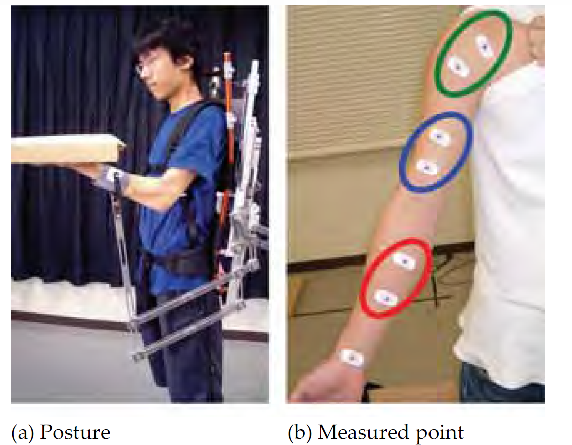
Experimental setup
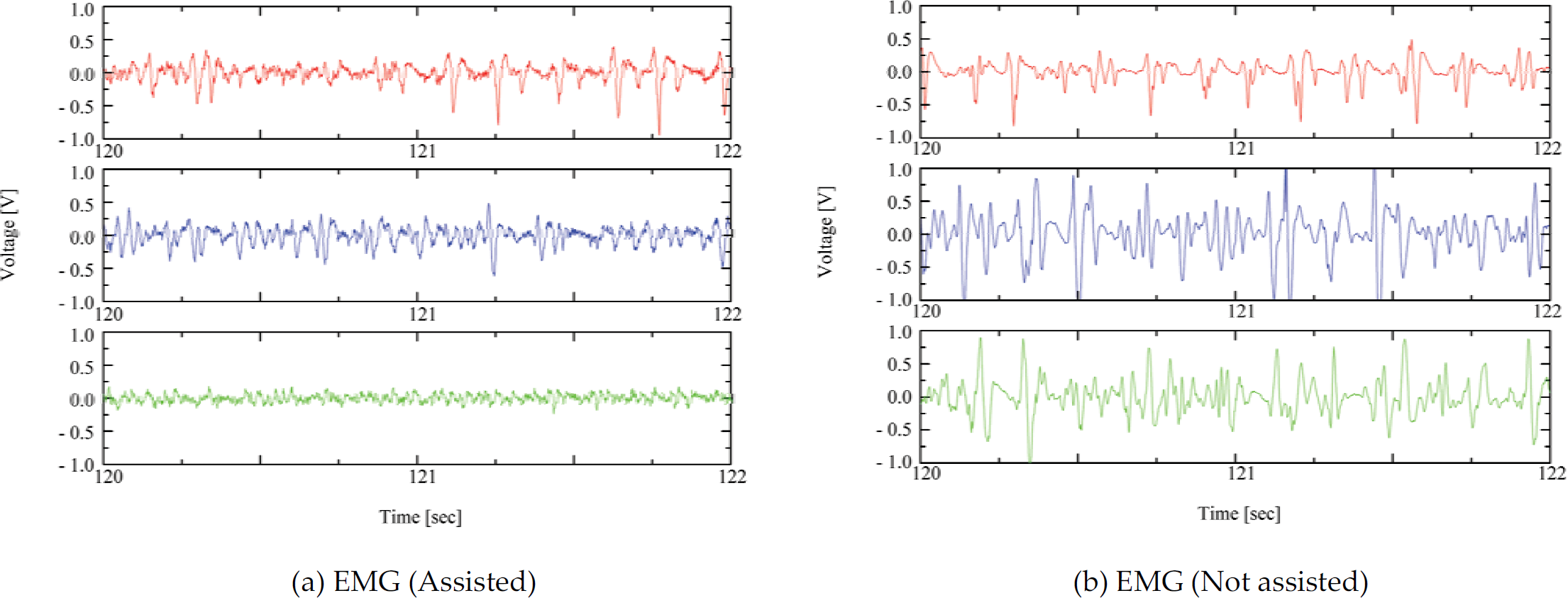
Measured EMG between 120–122 sec.
To show the difference between assisted performance and not assisted, we focus on the range of 120 to 122 seconds and show the difference in Fig. 12–a) (using the robot) and Fig. 12-(b) (not using the robot). Comparing Fig. 12-(a) with Fig. 12-(b), all of the waveforms in Fig. 12-(a) are smaller than in Fig. 12-(b). Deserving special mention is the deltoid muscle, where it was found that the subject felt much less tiredness in comparison.
Results on IEMG and MNF
When we want to see the difference of each characteristic easily, checking the waveform directly is good. In addition, when we want to judge it quantitatively, integrated electromyogram (IEMG [V·s]) is often used. IEMG was given as follows:
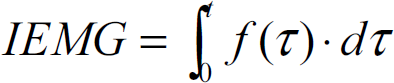
One way to survey the muscular output force and muscle fatigue is to check the IEMG magnitude. It shows that when muscle has fatigue, the size of EMG is bigger. Therefore, IEMG shows a transition of the level of muscle fatigue. Figure 13 shows a subject's IEMG transition. Magnitudes of all muscles of not using robot are bigger than using robot, so it shows that robot worked effectively for a subject. Checking that figure of elbow and shoulder, it is shown that level of some IEMG is increasing as time passes especially the transition of not using robot is larger than using ones. However, the brachii muscle's data does not show large transition of IEMG. It is because the muscle load is often affected by the angle of joint sensitively. Therefore, when we want to know the muscle fatigue, the MeaN power Frequency (MNF [Hz]) is usually used. It is calculated as follows (Kizuka, T. et al, 2006);

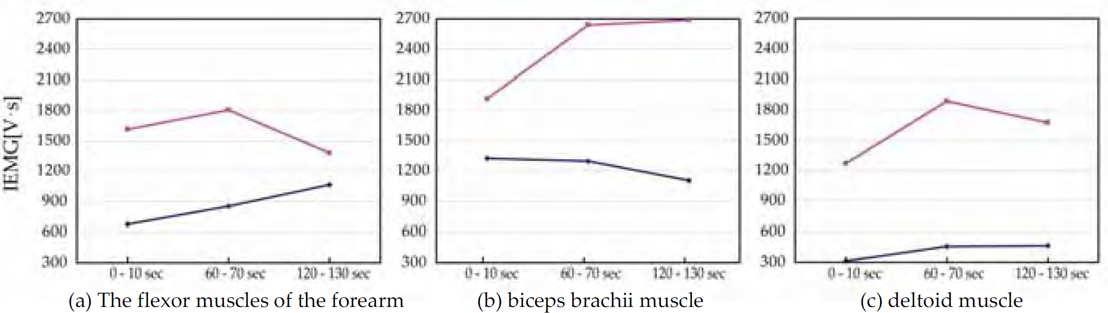
Measured IEMG of a subject (Using robot is drawn in blue and not using it is drawn in red)
Where f Hz is frequency and P(f) is normalized power spectrum obtained by FFT analysis. This method uses the characteristics of muscles, i.e. as muscles get fatigued, they generate low frequency. Thus we can easily understand how much fatigue muscles get by checking the reduction ratio of MNF. MNF results are as shown in Fig. 14. In this figure, to understand the changing ratio of MNF clearly, we averaged MNF value by the three subjects' data and normalized it by the MNF value of 0–10 seconds. And then we plotted with standard deviation. Compared with bracii muscle and deltoid muscles' MNF data of using robot and not using robot, it is easily underhanded that there is great deference between the two data. On the other hand, there is not great difference at the flexor muscles of the forearm. This is because the robot assist only forearm, so the robot does not assist the wrist torque (i.e. the flexor muscles of the forearm). These MNF results clearly show the accuracy of this experiment and prove that the robot gives subjects assistive force and it works well.

Normalized and averaged MNF of three subjects (Using robot is drawn in blue and not using it is drawn in red)
In this paper, we proposed an original method for assisting a carpentry worker to support boards and explained the developments of a prototype robot for this propose. The specification of the prototype has been evaluated. Experiments were conducted to show the effectiveness of the robot and good results were obtained. Hence energy saving design was successful, a large range of movement was obtained and compliance gave the worker comfortable mobility. Moreover, by using the robot, muscle output force is reduced and muscle fatigue was also clearly reduced. However, these experiments only showed that this robot works for the arms. In order to have better comparison, we will have to measure the effectiveness of the total energy consumption of workers. In addition, the prototype still has some problems, like large mass, low adjusting speed and large size. Therefore, we will have to develop a more practical robot. Further research will be required for realizing a more practical design. Then, the next stage is how to operate it effectively.
Footnotes
6. Acknowledgment
We would like to thank for Yamamoto, K. technical official for his great assistance and advice about developing the wearable robot. Finally, we wish to thank the Prof. Dutta for his constructive comments, which significantly improved an earlier version of this paper.