
Abstract
To run a tactical unmanned aerial vehicle (UAV), efficient information transmission schemes, such as beamforming, are preferred due to the limit of the payload. Therefore, beam tracking and localization algorithms are considered to be one of the key technologies. In this paper, we propose a coordinated UAV localization algorithm for a tactical scenario where the ground receivers are connected with wireless limited lower rate backhaul and are closely spaced. By applying the αβ filter to the conventional scheme, we first show that the localization performance can be improved significantly. We also propose an efficient localization algorithm for a system with low rate limited feedback. Using numerical simulations, we show that the proposed scheme can improve the localization performance while reducing the feedback over conventional scheme.
1. Introduction
Over the past several years, there has been a gradual development of military technologies and a series of new concepts. As the technologies based on surveillance, security systems and the transmission of information are growing rapidly, a new aspect sometimes called network centric warfare (NCW) has been confronted. For NCW, it is important to offer a shared awareness of the battle space for our forces [1]. The tactical information of battle space can be acquired by an intelligence, surveillance and reconnaissance (ISR) system that collects, processes and sends data in support of current and future military operations [2].
There are many ways to collect tactical information. A satellite obtains wide area intelligence, which often imposes a high cost and a lack of flexibility. Although manned aircraft have flexibility in attempting a mission, there exists a high risk of the loss of pilots' lives. On the other hand, an unmanned aerial vehicle (UAV) carries no risk of pilots' lives and can sometimes carry thermal cameras [3] that can see through darkness or rain. UAVs, therefore, have drawn attention in surveillance due to their flexibilities.
Since low power and light type transmission armament on a UAV are preferred due to the payload limitation, the transceiver on the surface of the ground is generally equipped with high-resolution/sharp beam-width antennas. Therefore, those systems need the beam-tracking algorithm, matching the boresight of the antenna to the signal direction. Also, it is necessary to grasp and keep track of the current position of the UAV. The most common form of estimating the direction/angle of the arrival signal is a monopulse technique [4, 5]. In a monopulse estimator, the sum and difference resulting patterns are obtained by adding and subtracting the signals from the two overlapping beam patterns. Then, the system keeps track of the angular position of the signal by comparing the monopulse ratio.
In this paper, we propose a tactical UAV localization algorithm using coordinated monopulse trackers; so-called ground control stations (GCSs). Each of the GCSs estimates the angular position of the UAV using the monopulse and sends their estimates to the main GCS. Then, the main GCS combines the angular estimates and decides the UAV site. To the best of authors' knowledge, there is a similar work in MIMO radar systems [6] (Extended results are presented in [7]). This radar system, however, has great capabilities to share the knowledge of the estimates, because this work assumed that all receivers (referred as GCSs in this system model) are connected with wired backhaul. For this reason, each of the receivers can send the perfect knowledge of the necessary information. Also, the receivers are widely spaced, which is a sufficient condition for achieving angular diversity. In contrast to these works, we consider a tactical scenario where all the GCSs are connected with wireless backhaul and closely spaced. Therefore, we consider not only the feedback burden for sharing their estimates but also the short distance between GCSs. We first investigate the enhanced localization performance by applying a filtering technique and propose a coordinated localization algorithm for closely spaced GCSs with low rate limited feedback.
The rest of this paper is organized as follows: Section 2 describes the system architecture in detail. In Section 3, signal-processing techniques, referred to as monopulse and filtering, are described. Also, the quantization problem of the limited feedback system is given. In Section 4, we propose a coordinated localization algorithm of this system model. In Section 5, the numerical results for localization performance are shown. Finally, conclusions are drawn in Section 6.
2. System Architecture
In this section, we describe the UAV system model. Figure 1 shows the basic structure of our interest based on the multiple GCSs. The UAV, equipped with omnidirectional antennas, transmits the tactical signal. Based on the UAV signal, each of the GCSs estimates the angular position of the UAV by the monopulse receiver with L number of linear arrays, where we only consider the azimuth angle of the UAV variation. Without loss of generality, it can be readily extended to the elevation dimension by adding vertical beams. The received signal vector of the i th GCS

Coordinated UAV tracking system
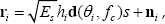
where

where
By measuring the received signal
3. Signal Processing & Model
3.1 Monopulse
Monopulse [4, 5] is a signal processing technique that estimates the angular position of a target (in this case, the UAV). It is associated with the linear array and antenna beamforming weights (see Fig. 2). The steering vector of the beamformer is defined as the complex amplitude profiles versus the UAV angle θu. For example, a UAV will have the following directional vector:

Monopulse receiver
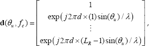
where d and λ denote the array spacing and wavelength corresponding to the carrier frequency fc' respectively. It is assumed that each of the array elements is uniformly spaced by half of the wavelength (s.t. d = λ/2).
Each GCS has two beamformers with overlapping patterns and their main beam directions are squinted at angle θs. Define the weights of the i th GCS two beamformers as

and
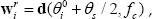
where

and

respectively. Then, the i th GCS monopulse ratio versus UAV angle θi within the main-beam is given by (see Fig. 3):

An example of the monopulse ratio qi(θt) in the case of L = 10 and θs = 10°

The angle of the UAV can be determined through a lookup table or by evaluating the monopulse ratio qt(θi).

where
3.2 αβ Filter
The αβ filter is probably one of the most extensively applied fixed coefficient filters. It produces smoothing estimates for position and velocity (in this case, angular position and angular velocity) on the tth sample time observation. It also produces a predicted position for the (t +1)th observation. Smoothing is done to reduce errors in the predicted position by adding a weighted difference between the measured and predicted values to the predicted values to the predicted position. Then, the αβ filter is defined as:

and

where

where T is the tracking period. The filter coefficients

Note that heavy smoothing (leaning toward the prediction) means ξ → 1 and little smoothing (leaning toward the observation) means ξ → 0. Also, Eq. (10-12) are referred to as the prediction, innovation and correction, respectively.
3.3 Quantization Level
In our system model, the distributed multiple GCSs are cooperating to keep track of the UAV where the cooperating GCSs send their estimates to the main GCS through the (low and limited rate) wireless backhaul. Therefore, the main GCS would receive imperfect estimates with a quantization error.
In this paper, we consider the uniform quantizer that divides the range R = [–2°, 2°] into the same width, denoted A due to its simplicity. Table 1, shows an example of the quantization level of the monopulse angular value
An example of a uniform distribution of the quantization angle according to the number of feedback bits

The mean squared error (MSE) of the quantization level is given by:

where fx(θ) denotes the probability density function (pdf) of estimates θ. If the uniform quantizer is applied and quantization interval A is small enough so that fx(θ) is approximately constant, we can readily approximate Eq. (15) as [8].

4. Localization Algorithm
4.1 Localization Procedure
In this subsection, we propose a UAV localization algorithm using a coordinated monopulse tracker with wireless backhaul.
Step 1: Initialization: GCS network
The GCSs are distributed to keep track of the UAV and set up the wireless network to the main GCS. In this step, the main GCS decides the number of feedback bits for cooperation and control of the UAV to the Rendezvous point. Then it notifies other GCSs to make sure UAV acquisition occurs. Along with this, each GCS sends their coordinate position (
Step 2: Angular tracking: Monopulse
After establishing the GCS networks, each GCS measures signals from the UAV and computes the monopulse ratio in Eq. (9). If the
Step 3: Feedback: Wireless backhaul
All the GCSs send their angular estimates to the main GCS. In our proposed algorithm, the feedback information is the difference between the boresight axis at present time t and at previous time t–1 (the boresight axis is shared at the first step so it is sufficient for catching up to the boresight axis of the i th GCS.) For given feedback bits, the angular estimates
where
Step 4: Filtering
The main GCS obtains the quantized angular estimates
Step 5: Localization
Then, the main GCS forms a polygon of N (N − 1) / 2 sides by connecting points of the intersection of the (quantized and refined) boresight from N number of GCSs. Let us define

An example of a polygon formed by three GCSs

and

where
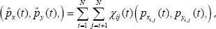
where χij is the weight that is proportional to the sum of decision factor Ei(t) from the corresponding GCSs.

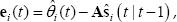
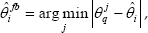
We now derive the decision rule jointly with the innovation process in Eq. (11). The innovation term of

where Ei(t) indicates the reliability factor of the estimates from the i th GCS during that instant of t and ∈ is an arbitrary small real number, which prevents the infinite value of Ei(t).
4.2 Conventional Localization Method
To the best of the authors' knowledge, there is a similar work [7] in MIMO radar systems. This radar system however, has an enough capabilities to share the knowledge of their estimates, because it is assumed that all receivers (referred to as GCSs in this work) are connected with wired backhaul. Therefore, each receiver sends perfect knowledge of not only angular estimates but also instantaneous energy without a critical burden, where the instantaneous energy is used for calculating the proportional weights. Therefore, the proportional weight of our model in Eq. (22) is replaced with:

Furthermore, the receivers are widely spaced so that they can provide a good localization performance without applying a filtering technique, due to the angular diversity. In contrast to this work, our system model is based on tactical receivers, so-called GCSs, where the GCSs are closely located and connected with low rate wireless backhaul.
5. Simulations
5.1 Simulation Environments
In this section, we consider numerical examples that compare the localization performance of the proposed algorithm with the limited low-rate feedback. In this example, we consider the system to have three GCSs (nR = 3) with ten monopulse arrays (L = 10) and the squint angle of monopulse tracker is ten degrees (θs = 10°) (see Fig. 3). The GCSs are located on the x-axis at the origin (0, 0), 1km (0, 1) and −1km (0, −1) from the origin, respectively.
In many cases, the dynamic trajectory of an UAV is modelled by the correlation between samples. We can model them using position and velocity, which change at each time step, to approximate the real continuous behaviour. Exploiting the first-order Gauss-Markov process, which can be defined from the correlation between consecutive samples [11, 12], the dynamics state model of the UAV position (px,py) can be represented as:

where vx and vy are the velocity of the x-axis and y-axis, respectively. Also, ηx and ηy denotes the dynamic state random variable of the UAV and they have a normal distribution of
The position of the UAV (px, py) may be viewed as the output of a linear time invariant system driven by ηx and ηy. In arriving at a model for the dynamics, we assume a constant velocity, perturbed only by wind gusts, slight speed correction, etc., as might occur in a UAV. Therefore, we set the variance of dynamic variable
Under this condition, the characteristics of UAV motion with 6000 samples (ten minutes) are depicted in Fig. 5 (a). The tracking period is 0.1 seconds (T = 0.1 seconds), an average UAV velocity is about 85km/h and the speed is moderately increased or decreased.
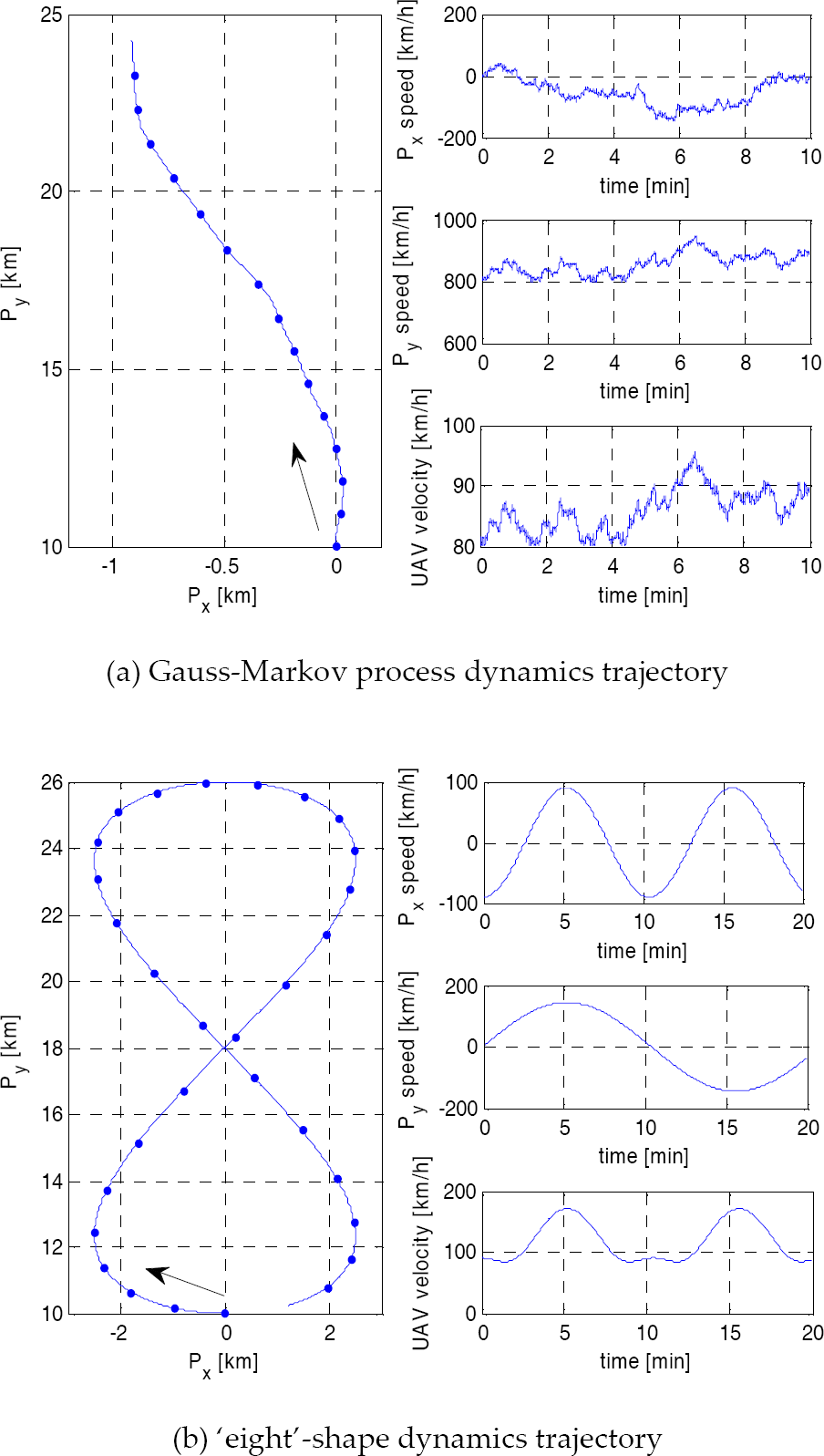
The UAV trajectory
We also compare the typical (scheduled) movement of a UAV, which is called the ‘eight’-shape dynamic trajectory. Using the sine and cosine wave, the ‘eight’-shape dynamic trajectory is given by:

and

where Rx and Ry denote the ‘eight’-circle of the radius of the x-axis and y-axis, respectively. We set Cx = 2.5, Cy = 8, fx= 0.00016 and fy = 0.00008. Under these conditions, the characteristics of UAV motion with 12000 samples (20 minutes) are depicted in Fig. 5 (b). Unlike the first Gauss-Markov process dynamic model, an ‘eight’-shape dynamic trajectory shows much lower boresight and faster varying acceleration, which might lead to the degradation of localization performance. The UAV is initially present (Rendezvous point) at the coordinate (px(0), py(0))= (0, 10). Also, we choose the smoothing factor ξ = 0.97 in the filter coefficients. It is assumed that the average received SNR of each GCS is equal and set to 15dB. The channel gain in Eq. (2) is modelled by Rician fading with K = 10.
It is noted that the conventional approach of Eq. (23) requires the additional quantization level of the instantaneous energy. Similarly to the angular quantizer, we consider that the uniform distribution of the quantization level of the instantaneous energy within certain range R = [0, 4].
5.2 Quantization Error Analysis
As mentioned in Section 3.3, we adopt the uniform quantizer that divides certain range R = [–2°, 2°] into the same width, denoted A (to compare the conventional work, quantization range R = [0, 4] of the instantaneous energy is chosen). The high-resolution (i.e., large 2b) approximation shows that the MSE is almost Δ2/12. Figure 6 (a) and (b) show the MSE of angular estimates and the instantaneous energy caused by quantization error. As we expected, the numerical results follow the analysis results from the high-resolution approximation When more than five bits are used for feedback, the average quantization error is less than 10−3. Therefore, we can expect that the system with five bits feedback can achieve a similar performance to the system with perfect knowledge of the estimates.

The MSE of angular estimates and instantaneous energy caused by quantization error
5.3 Localization Performance
We now turn our focus to the localization performance of the proposed method. At first, Fig. 7 shows the highest (20%) cumulative distribution functions (CDFs) of the localization error with a perfect knowledge of the angular estimates and the instantaneous energies, when a Gauss-Markov process dynamics trajectory (see Fig. 5 (a)) of the UAV is applied. Without a filtering technique (denoted as ‘Conv’), the localization error of the 20% outage probability is more than 1km. When we apply the filtering technique (denoted as ‘Conv+Filter’) to the conventional localization method, the performance of the localization is remarkably improved. The proposed method (denoted as ‘Prop’) has almost the same localization performance when compared to the conventional method with a filtering technique.

The CDFs of localization error with perfect knowledge of estimates; “Conv” and “Prop” denote the conventional and proposed method, respectively (Gauss-Markov process dynamics trajectory)
Next, we investigate the localization performance with an imperfect knowledge of the angular estimates and instantaneous energies. Fig. 8 to 10 show the CDFs of the localization error with a limited feedback rate for each method, respectively. We clearly see from Fig. 8 that the conventional method requires more than ten bits per sample (five bits for the angular estimates and five bits for instantaneous energy) to achieve a similar performance to a perfect knowledge system. When the number of feedback bits is reduced to four bits per sample, the performance gap is increased to 2km. Similarly, the conventional method with a filtering technique requires ten bits to catch up with the perfect knowledge system (see Fig. 9).

The CDFs of localization error for a conventional method on the consideration of the number of feedback bits (Gauss-Markov process dynamics trajectory)

The CDFs of localization error for a conventional method with a filtering technique on the consideration of the number of feedback bits (Gauss-Markov process dynamics trajectory)

The CDFs of localization error for the proposed method on the consideration of the number of feedback bits (Gauss-Markov process dynamics trajectory)
Additionally, the localization performance is degraded when the number of feedback bits is reduced. However, its degradation is weaker than the conventional method since the filtering refines the imperfect knowledge of the estimates.
For the proposed method, only five bits feedback per sample is enough to catch up with the perfect knowledge system, as shown in Fig. 10. Since the proposed method has a different localization rule that does not need the feedback information about instantaneous energy, it can cut down the number of feedback bits. Considering a performance gap between the proposed method and the conventional method with a filtering technique in Fig. 8, the proposed method with five bits feedback per sample has a similar localization performance to an eight bits feedback system for the conventional method with a filtering technique.
Figures 11 to 14 show the localization performance of each method for a perfect and imperfect (considering the number of feedback bits) knowledge of estimates, when the ‘eight’-shape dynamics trajectory (see Fig. 5 (b)) is applied. In this case, the dynamic trajectory shows a much lower boresight and faster varying acceleration, which might lead to the degradation of the localization performance. For example, when the boresight angles of the i -th and the j -th GCS are similar, the shape of the polygon is severally longish toward those boresight directions. Therefore, the connection point of the i -th and the j -th GCS might be far from the target-site and this vertex induces (outage) performance degradation. Compared to the Gauss-Markov process dynamic trajectory, the localization performance is quite similar but is 23% degraded. Without a filtering technique the localization error of the 20% outage probability is more than 1.23km (from a 1km error for Gauss-Markov). The localization performance of the conventional method is improved by applying the filtering process and the proposed method can achieve the near “Conv+Filter” method, while still saving the feedback burden.

The CDFs of localization error with perfect knowledge of estimates; “Conv” and “Prop” denote the conventional and proposed method, respectively (‘eight’-shape dynamics trajectory)

The CDFs of localization error for a conventional method on the consideration of the number of feedback bits (‘eight’-shape dynamics trajectory)

The CDFs of localization error for a conventional method with a filtering technique on the consideration of the number of feedback bits (‘eight’-shape dynamics trajectory)
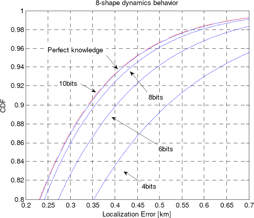
The CDFs of localization error for the proposed method on the consideration of the number of feedback bits (‘eight’-shape dynamics trajectory)
6. Conclusion
In this paper, we investigated a coordinated UAV localization algorithm by tactical receivers, a so-called GCS. In our system model, the tactical GCSs are closely spaced and connected with wireless low rate backhaul so that the system cannot meet enough angular diversity and has limited capabilities to share the estimates. We first applied the αβ filter to refine the target localization and showed the improved UAV localization ability of the filtering technique. Furthermore, we proposed a tracking algorithm considering limited feedback. Simulations showed that the proposed method improves the localization performance while reducing the feedback from GCSs.
Footnotes
7. Acknowledgments
This work was supported by the Agency for Defense Development (ADD in Republic of Korea) and the IT R&D programme of MOTIE/KEIT [10035389 - research on high speed and low power wireless communication SoC for high-resolution video information mining].