
Abstract
In the development of robots and machine tools, in addition to conventional and serial structures, parallel mechanism-based kinematic structures have been used over a longer period of time. Aside from a number of advantages, the irregular shape and relatively small dimensions of the workspace formed by parallel mechanisms rank among the major weaknesses of their application. Accordingly, this fact has to be taken into consideration in the process of designing parallel mechanism-based robots or machine tools. This paper describes the categorization of criteria for the conceptual design of parallel mechanism-based robots or machine tools, resulting from workspace analysis as well as the procedure of their defining. Furthermore, it also presents the designing methodology that was implemented into the program for the creation of a robot or machine tool space model and the optimization of the resulting solution. For verification of the criteria and the programme suite, three common (conceptually different) mechanisms with a similar mechanical structure and kinematic characteristics were used.
1. Introduction
Robot systems and machine tools constitute the basis of production systems [1]. Encouraged by increased technical and technological demands targeted at products, over the last few years intensive research has been conducted which was aimed at improving robots and machine tools, both from the aspect of their construction, as well as components to be installed therein. In this way, specific constraints have been detected in robots and machine tools developed on the basis of serial kinematic structure. It first of all implies constraints in the feed rates, achieved level of technical development of specific components, high cost etc. [2]. Accordingly, over the last twenty years, theoretical and experimental research has been intensified with a view to the modification and upgrading of both robots and machine tools structures by introducing parallel and hybrid serial-parallel kinematic structures [3].
One of the restrictive factors on the wider use of parallel mechanisms in practice is the fact that the workspace formed is not of regular geometric shape, as is the case in robot systems and machine tools with serial kinematics [4]. As a result, a number of pieces of research were conducted [5–7] with a view to defining the dimensions and topological characteristics of the workspace of parallel mechanism-based robots and machine tools. The complexity of the workspace geometric shape in these mechanisms is one of the reasons that the obtained results have been used lately to define the designing methodology for parallel mechanism-based robots and machine tools [8–10]. As the basic designing methodology, appropriate criteria resulting from analytical and numerical analyses of the workspace shapes and dimensions are used [8, 12].
This paper demonstrates the results of research that has been conducted with a view to the implementation of specific features of parallel mechanisms' workspaces into the process of robot systems and machine tools design. With that in mind, the research has been split into two sections: defining the criteria for designing the workspace shapes and dimensions obtained by the analysis and developing the program suite for the conceptual design of robots and machine tools. In the process of the research implementation, with the aim of verifying results of both research phases, three parallel mechanisms of similar structural and kinematic features were used.
2. Materials and methods
2.1 Properties of parallel mechanisms, which are significant in the designing process
Designing a robot and machine tools concept, among other things, includes defining of a number of parameters resulting from the analysis of the mechanism kinematics (direct and inverse), as well as movement constraints [13] resulting from the structure of specific components.
Furthermore, the properties of parallel mechanisms are presented both in view of kinematics and the constraints found in joints and struts of the mechanism. Keeping in mind that the analysed field involves a great number of developed parallel mechanisms, for illustrative purposes, the three typical types of parallel mechanisms have been selected for further analyses are tripod, triaglide and ortoglide. The above-mentioned mechanisms have been selected due to the following reasons:
The selected parallel mechanisms have a mobile platform with three degrees of freedom
The bases of the above mentioned mechanisms, according to their shape and structure, represent the three most commonly used shapes in robots and machine tools
The mechanisms are constructed on the basis of the two most frequently applied types of struts
The above-mentioned mechanisms constitute a structure suitable for designing robots and machine tools on reconfigurable principles.
Therefore, it can be concluded that these are structurally similar mechanisms, which will be compared throughout all phases of the analysis
2.1.1 Tripod Mechanism
In theory, the tripod mechanism is considered the most common parallel mechanism in terms of its construction, which was developed from the original Stewart's mechanism [4]. The mechanism structure consists of two platforms (the immobile – a base and the mobile), which are interconnected by means of struts of variable length (Figure 1a) [7]. Spherical and universal joints constitute connecting elements between struts and platforms. The workspace analysis of the tripod mechanism includes the resolution of its inverse kinematics, i.e., the analysis of the vector polygon comprising the base, one of the mechanism struts and the mobile platform. The vector polygon comprising the tripod mechanism with three degrees of freedom of the mobile platform is shown in Figure 1b.

Tripod mechanism and vector polygon of the mechanism

The struts' vectors and the position of individual joints are defined by solving the inverse kinematic chain of the tripod mechanism. In this case, this involves defining vector
In addition to the movement regularity, the theoretical analysis also has to include constraints arising from the construction characteristics of specific mechanism components. These include [14]:
Marginal length of struts (for all struts, i = 1, 2, 3):

Marginal rotation angles of specific joints (for all joints, i = 1, 2, 3):

Mnimum distance between the struts (in order to prevent their collision), for i, j = 1, 2, 3:

On the basis of the equation system (1) to (5), by solving the inverse kinematics, the vector components li (as well as the struts lengths) are obtained for each position of the mobile platform. By verifying whether the constraints are within the range of set values for each analysed position of the mobile platform and by eliminating the points where those constraints are not met, a cloud of points is formed, delineating the workspace.
2.1.2 Triaglide Mechanism
The triaglide mechanism is a more advanced type of parallel mechanism developed with a view to obtaining the workspace of as regular a geometric shape as possible, with a more simplified construction and at a lower cost [15, 16].
The triaglide mechanism differs from the previously analysed tripod mechanism in two aspects: base construction and construction of struts, which are of fixed length in this case.
The base structure of the triaglide mechanism comprises three separate, parallel guides (Figure 2a). The sliders attached to the struts slide along the guides, whereas the other end of the struts is affixed to the mobile platform. Spherical or universal joints are used as connecting elements between struts and the base, that is, the mobile platform. Figure 2b shows the arrangement of vectors circumscribing the position of the mobile platform in relation to one of the mechanism struts.

Triaglide mechanism and vectors' polygon of the mechanism
On the basis of such defined vectors' polygons, the following equations are obtained for all three sliders (i = 1, 2, 3) which, in general form, can be expressed as follows (6):

In the case of the triaglide mechanism, unknown values represent the sliders positions on the mechanism base
Value y in vector
For further analysis of the triaglide mechanism kinematics, it is necessary to take into consideration the constraints on the triaglide mechanism. The following constraints are found in the triaglide mechanism:
Maximum travel of sliders
Marginal rotation angles in specific joints (for all joints, i = 1, 2, 3)


Distance between the struts (for i, j = 1, 2, 3)

2.1.3 Ortoglide mechanism
Conceptually, the ortoglide mechanism represents a modified version of the triaglide mechanism, the base of which consists of the three orthogonal guides [6]. The base of this type of parallel mechanism comprises three orthogonal guides along which the sliders linked by the fixed-length struts slide. On the other end, the struts are linked to the mobile platform by means of universal or spherical joints. Figure 3 shows a visual model of the ortoglide mechanism [6] (Figure 3a), as well as the arrangement of vectors on the ortoglide mechanism (Figure 3b).

Ortoglide mechanism [17] and vectors' polygon of the mechanism
On the basis of the vector polygon shown in Figure 3, the following regularities defining the position of the mobile platform in space can be established, which in its general form reads as follows (for all vector polygons i = 1, 2, 3):

In the ortoglide mechanism the unknown values, joint positions
In Equation (12)

Constraints arising from the ortoglide mechanism structure have considerable bearing on the mechanism kinematics. These include:
Maximum travel of the sliders

Marginal rotation angles in specific joints (for all struts, i = 1, 2, 3)


Distance between the struts (for i, j = 1, 2, 3)

2.2 Analysis of parallel mechanisms' workspace
In the robot and machine tools design process the workspace analysis represents one of several phases, which enables preliminary defining of major geometric properties. Previous analyses of the workspace have pointed out its significance and impact on the application of these machines in the exploitation process [9, 11,18]. Research has proved that the geometric properties of the workspace depend on a number of parameters among which are as follows: the type and dimensions of the mechanism, the structure of specific components etc. Accordingly, the analysis of regularities affecting the shape and dimensions of the parallel mechanisms' workspace enables the definition of the procedure for the conceptual design of robots and machine tools of this type [4, 19].
For the purpose of multi-criteria workspace analysis of different types of parallel mechanisms, the specific software “Workspace” was developed. Its application provides the definition of all the relevant parameters for the examination and categorization of workspaces of parallel mechanisms as well as their comparative analysis. The “Workspace” program processor employs a discrete mathematical analysis based on the inverse kinematics of the mechanism, which is considered the most suitable method for defining and analysing the mechanism components for a predefined workspace [8].
The following section describes the concept of the developed program first, which is then followed by the results of analyses obtained by its application.
The complexity of the workspace concept of robots and machine tools generally involves a series of analyses of its geometric properties. Therefore, the program is designed so as to facilitate the definition and analysis of the parallel mechanism workspace in several phases [20]:
Defining the workspace spatial model of the mechanism as a set of points in the space at which the mobile platform can be positioned for specific configuration of structure components. This provides a detailed visual analysis.
Creating the matrix of coordinates delineating the workspace with a view to subsequent analysis of its properties.
Establishing the values typical of the workspace: overall dimensions and volume of the workspace, ratio between actual and ideal volume etc.
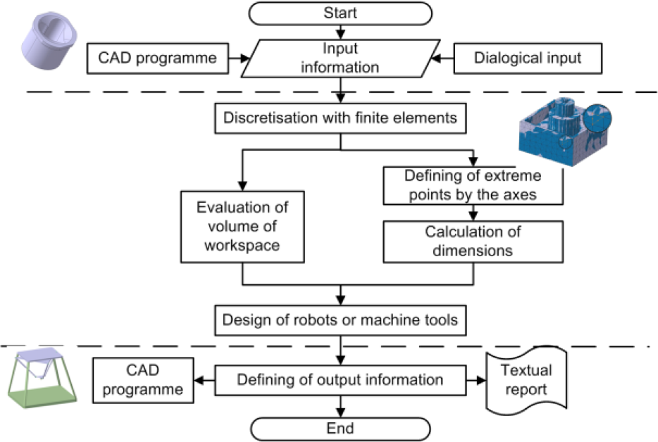
The model of the “Workspace” software structure is shown in Figure 4.

“Workspace” software model [18]
Following post-processing, the analysis results are presented in the two ways:
By means of the numerical values, volume and overall dimensions of the workspace, displayed in the command window of the software.
By means of the workspace spatial model of the parallel mechanism, which is generated within the subsystem for visualization of graphical objects, enabling the generation of different graphical presentations. This subsystem constitutes an integral part of Matlab program application, in which “Workspace” is developed, thereby considerably facilitating the generation of graphical results and their manipulation (Figure 5).
Graphical presentation of the analysis results
The combination of numerical and graphical presentation forms of outputs ensures higher quality analysis of the workspace [21].
2.3 Defining the criteria for selection of the type and parameters of the parallel mechanism
Detailed workspace analyses of different types of parallel mechanisms point to its influence on specific components of the mechanism. Thus, by inverse procedure of establishing mathematical regularities of the impact of the mechanism components, dimensions on shape, dimensions and anomalies, the criteria for the conceptual design of the mechanism may be defined.
On the basis of the workspace analysis results for different types of parallel mechanisms, it is possible to define criteria for their selection, which may be classified as follows:
Criteria concerning the workspace shape
Criteria concerning the mechanism overall dimensions and the workspace volume
Additional geometric criteria.
2.3.1 Criteria concerning the workspace shape
On the basis of the analysis of parallel mechanisms, it has been established that the most significant differences between workspaces that are created in robots and machine tools is manifested in their shape and dimensions. For this reason, a number of pieces of research have been undertaken over the recent years aimed at the categorization of shapes of parallel mechanisms' workspace and the introduction of parameters enabling their comparison with the workspace of machine tools with serial kinematics [5, 11, 22]. In order to interpret those distinctions, the coefficients of ratios between the mechanisms' overall dimensions and their workspace are used on the basis of which the appropriate dependencies are established. In the section below we will show the ratio of the workspace's overall dimensions as dependent on the mechanism volume, which results from the workspace analysis of around 50 configurations of specific mechanism types. This is followed by the graphic presentation of the dependency of the struts' length for every individual mechanism subject to the workspace dimensions. Accordingly, functional dependencies among criteria for establishing the struts' length will be defined.
Due to the comprehensiveness of the analysis, this paper presents a criterion to define the struts' lengths, whereas criteria to determine the mobile platform and base dimensions are not presented.
3. Tripod mechanism
The workspace of the tripod mechanism is of pyramidal shape with an irregular triangular base. Figure 6 illustrates a workspace example for one of analysed tripod mechanism solutions.

Tripod mechanism workspace [5]
According to the example illustrated in Figure 6, it may be established that regularity of the workspace scope varies following the direction of specific axes of the rectangular coordinate system.
Figure 7 shows the dependencies of the workspace shapes (defined by the ratio between its overall dimensions) of the tripod mechanism on its volume in cases where there are no holes in the workspace affecting its function. The workspace analysis proved that this results from the ratio of the base dimensions and maximum struts' length Rbase/lmax ≤ 0,5.

Dependency of the ratio of overall dimensions on the workspace volume
On the other hand, the workspace analysis also enabled the definition of expressions linking the maximum strut dimensions with the workspace dimensions in the direction of specific axes. As a result, we obtain one of the criteria for the preliminary dimensioning of struts in designing robots or machine tools. Figure 8a shows the dependency of struts' length of the tripod mechanism on the overall dimensions of the workspace in the direction of one of the axes in the base plane (marked as the x-axis), for different base dimensions. Figure 8b shows the dependency of the maximum length of struts (lmax) on the overall dimensions of the workspace in the direction of the third axis, perpendicular to the mechanism base (marked as the z-axis in Figure 8b).

Dependency of the maximum length of struts on the workspace dimensions in the direction of the mechanism base axis (a) and the axis perpendicular to the base (b)
The above figures demonstrate linear regularities between the maximum length of the struts and the overall workspace dimensions in the direction of the x and z-axes. Mathematical expressions of regularities, which were established by linear interpolation between resulting points in the software Origin Pro, are shown in the bottom right corner of the figure.
4. Triaglide mechanism
The triaglide mechanism base structure has significantly influenced the workspace shape of this type of mechanism. Figure 9 shows the workspace of one of the analysed triaglide mechanisms.

Workspace of the triaglide mechanism
As is the case with the tripod mechanism, under specific circumstances, there are also holes emerging within the workspace volume of the triaglide mechanism. This irregularity in the volume occurs when the ratio between the length of guides of the triaglide mechanism and the length of struts (Xmax/Lstrut) is less than or equal to the value of 2 (Xmax/Lstrut≤2).
Figure 10 illustrates the functional dependency of the struts' length (ls) on the overall dimensions of the workspace (in the direction of the guides' axis), for different lengths of guides.

Dependency of the struts' length on the workspace dimensions in the direction of the guides' axis of the triaglide mechanism (x-axis)
The above figure shows linear regularity with a view to defining the length of struts depending on the overall workspace dimensions. The expressions, which define that dependency are shown in the bottom right corner of the figure.
5. Ortoglide mechanism
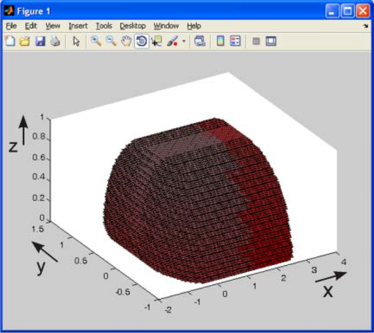
The workspace of the ortoglide mechanism (Figure 11) is subject to orthogonal sliding of the guides, which is why it is often compared with the serial kinematics mechanisms.
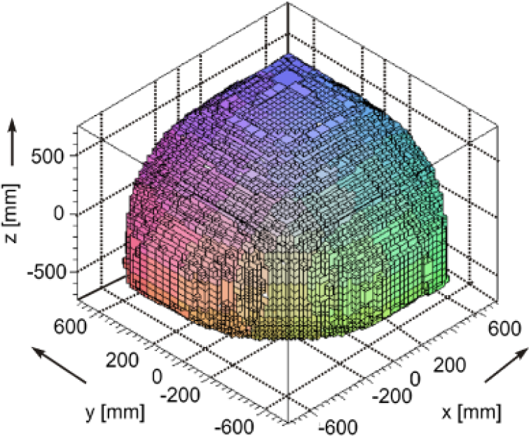
The workspace model of the ortoglide mechanism [23]
For this mechanism, in accordance with the workspace analyses, the regularities outlined by the struts' length subject to the workspace dimensions have been defined.
Figure 12 shows the dependency of the struts' length on the overall workspace dimensions in the direction of one of the spatial axes (marked by x). Due to the workspace symmetry, almost identical regularities are obtained for all the three axes.

Dependency of the struts' length on the workspace dimensions in the direction of „x-axis” of the ortoglide mechanism
2.3.2 Criteria resulting from the mechanism overall dimensions and the workspace volume
Mathematical regularities that describe dependencies between the volumes and dimensions of the mechanism itself and the workspace are used to define criteria for selection of the mechanism type. These criteria are established by defining the ratio between the volume of the parallel mechanism workspace (Vw) and the box volume (Vpm) into which it is circumscribed. That ratio is called a coefficient of the workspace occupancy (Cfw).

The workspace volume value (Vw) is obtained from the matrix of coordinates delineating the parallel mechanism workspace resulting from the “Workspace” software. Elementary volumes (also box shaped) whose dimensions are determined by the distance between the adjacent coordinates are introduced into each coordinate of the space defined by the matrix.
Figure 13 shows the dependency of the Cfw coefficient on the parallel mechanism overall dimensions (illustrated by the quotient of the overall dimensions of the base and the struts' length).
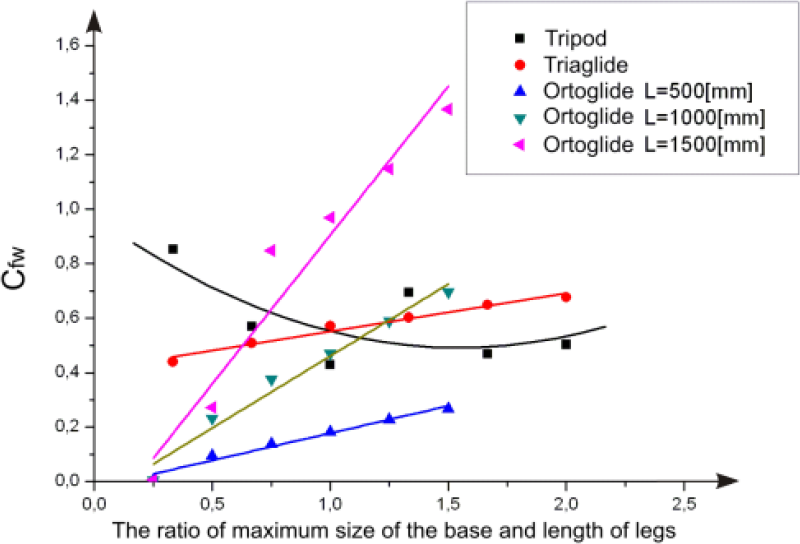
Dependency of the workspace occupancy coefficient on overall dimensions of the base and struts' length
The coefficients of workspace occupancy (Cfw) in the ortoglide mechanisms are represented by the three linear regularities for the different struts' length. This indicates that this criterion may also be applied, after establishing the effect of the struts' length on the coefficient of the straight line direction and in combination with other criteria.
On the basis of Figure 13, it can be established that from the aspect of the workspace occupancy coefficient (Cfw), for the ratios between the maximum overall dimensions of the base and struts' length of less than one, the tripod mechanism is the most suitable for application in robots and machine tools. Accordingly, it has also been found that for the greater values of the aforementioned ratio, the triaglide mechanism will be more suitable.
2.3.3 Additional criteria
In conceptual designing of robot systems and machine tools based on parallel mechanisms, in addition to the workspace, the additional criteria also have a significant role [12]. Some of these criteria are specified below:
Additional kinematic criteria, which take into consideration singular points
Criteria of the mechanism dynamics
Reconfigurability criteria
Criteria concerning the robot or machine tool construction price
Criteria pertaining to maintenance costs
Application of the additional criteria rounds off the process of designing parallel mechanism-based robots and machine tools.
2.4 Process of selecting the parallel mechanism type and dimensions
In the selection of the parallel mechanism type and dimensions phase, as well as in the process of optimization of the adopted solution, there are a greater number of criteria, which need to be fulfilled [10]. Thus, the designing process becomes significantly more complex, since it is impossible to meet all the criteria at once.
Figure 14 shows the block diagram for the process of designing parallel mechanism-based robots or machine tools while specific decision making criteria are applied.

Process of designing parallel mechanism-based robots and machine tools
The presented process involves a series of activities common to the designing process, which is adjusted to automation in this case.
3. Programme suite for the automated design
Automation of the designing process includes the application of a specialized program suite by which specific phases of this process are implemented free from the designer's influence. In addition, in parallel mechanism-based robots or machine tools it is possible to have specific phases automated such as:
Processing of the input information and preparation for designing of parallel mechanisms
Selection of the parallel mechanism type
Selection of the mechanism components based on the defined criteria
Optimization of the obtained solution
With a view to faster and more efficient development, these systems have been developed lately as modules to be integrated into software for designing universal purpose products (CAD)
3.1 Programme suite global structure
With a view to the automation of the conceptual design of parallel mechanism-based robots and machine tools, the program suite “Parallel mechanism” has been developed. The program suite was developed in Visual Basic for Application program language and implemented into CATIA V5 R19 software. The main purpose of this software is to select a type of the parallel mechanism and define a conceptual solution on the basis of the CAD model of a work piece.
The programme suite “Parallel mechanism” allows the execution of a greater number of actions in the process of selection of a parallel mechanism type and its structural components as a basis for the future robot or machine tool. These include the following:
Establishing the input information by discretization of the work piece applying CATIA Advanced Mesh Tools module
Processing the input information in line with the requirements arising from the designing criteria
A work piece analysis concerning the overall dimensions, shape and volume
Selection of the parallel mechanism type
Preliminary selection of the parallel mechanism components
Corrective analyses aimed at optimization of the selected mechanism
Completing the output results
As is evident from the requirements for designing software, their fulfilment includes the application of a modular building concept. Additionally, specific modules are classified, according to their function, into relevant subsystems (pre-processor, processor and post-processor). Each of these subsystems comprises a series of modules as well as communication with a database, which includes the parameters required for modelling the parallel mechanism components. Accordingly, each subsystem of the programme suite has the possibility to function independently as well as to access the information on the mechanism components and parameters of their optimization. Figure 15 shows a general model of the program suite for automated design of robots or machine tools.
General model of the program suite for designing of parallel mechanism-based robots and machine tools – “Parallel mechanism”
3.1.1 Pre-processor
The analysis of parallel mechanism-based robots and machine tools proved that the best method for the automation of their designing process, on the basis of the mechanism workspace characteristics, is a method of discretization of the object model to be manipulated by a robot (or processed by a machine tool) in order to define its shape and topology in the process of establishing the input information. In that way, the analysis of the robot end effector's access (or machine tool) to the work piece comes down to the analysis of whether each node of the discretized model belongs to the workspace of the proposed mechanism. As a result, the concept of the programme suite shown in Figure 15 includes the discretization of the work piece computer model, as the method of input information processing. This creates a suitable basis for the selection of the parallel mechanism type and its components.
The input information entered into the programme suite represents the computer model of the work piece formed in CATIA software. The analysis parameters are entered into the software by means of the dialogue and contain information on the type of analysis and model discretization. The programme suite module performing the function of establishing and processing the input information is a segment of the pre-processor subsystem. In addition, the pre-processor subsystem is expected to provide an adequate mathematical interpretation of the discretized model.
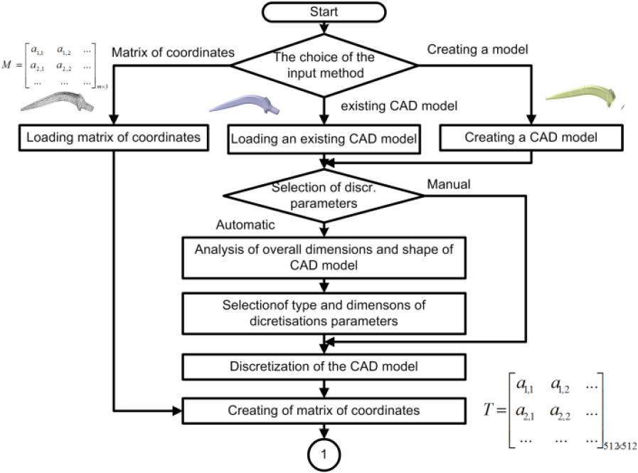
Pre-processor
The output database constitutes the exit from the pre-processor in the form of a matrix of node coordinates of the discretized model.
3.1.2 Processor
The processor subsystem makes the central unit of the program suite, which is comprised of a greater number of modules. This subsystem implements conceptual design through the following tasks: analysis of the type and shape of the discretized model, preliminary selection of the mechanism type, selection of the mechanism components and optimization of the obtained result
The analysis of the discretized work piece model is conducted through preliminary analysis of the overall dimensions and shape of the discretized model. The selection of the mechanism type consists of a comparison of the work piece model with workspaces of various parallel mechanisms available in the database and the adoption of the mechanism type. In addition, it is also verified whether each coordinate on the discretized model is available to the end effector of the mechanism. Optimization of the obtained solution in the current phase of the programme suite development includes comparison of the mechanism component dimensions with the existing mechanisms in the database. The aforementioned procedures are employed to adjust the dimensions of platforms and struts along with the analysis of compliance with the set criteria.

Processor
The output values coming out of the processor reach a conceptual solution to the parallel mechanism defined by a series of parameters, which determine the geometry of all its components.
3.1.3 Postprocessor
The post-processor subsystem consists of modules, which are aimed at processing the obtained numerical results and their modelling into a form suitable for further use. This unit of the program suite also comprises the module for the generation of the output results in a graphical form (in a form of a model of the designed machine tool) or in a form of the alphanumeric report. Figure 18 shows a block diagram of the postprocessor.
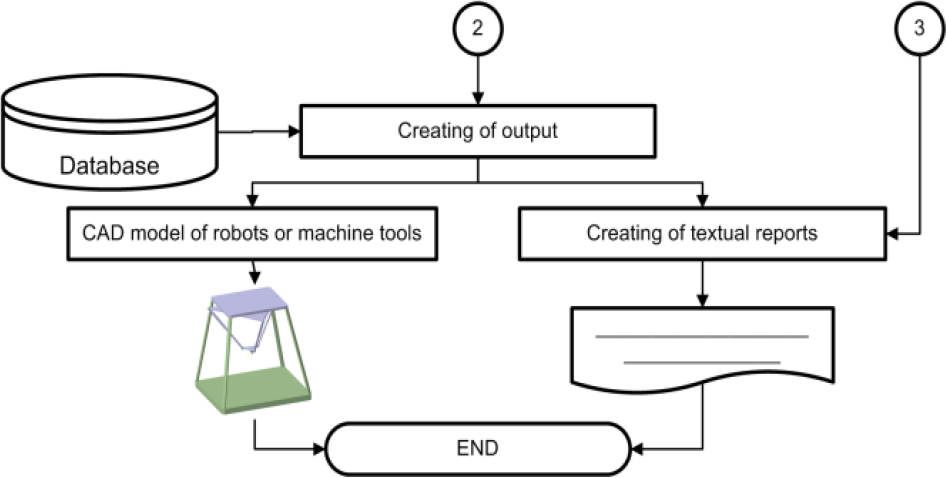
Postprocessor
4. Programme suite verification
As has been previously established, “Parallel mechanism” is a complex program solution, which, within a number of subsections, includes the following:
A great number of mathematical procedures
Communication protocols by means of which the connection with the databases is established
Communication with a subsystems of CATIA
Graphically-oriented user interface
The verification process of such a program suite includes a series of partial analyses of results of each typical subsystem, program unit and module. This process has been implemented in several spatial models of work pieces, which have characteristics of the parts that are being processed by the parallel mechanism-based machine tools.
Accordingly, the programme suite verification in this paper was carried out by designing a machine tool for the development of the two specific work pieces: a turbine impeller (Figure 19 a)) and a femoral hip stem (Figure 19 b)).
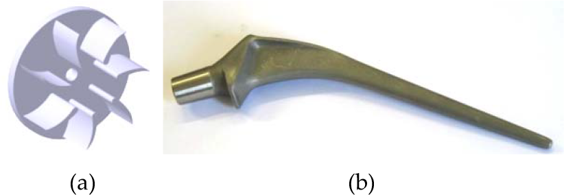
Turbine impeller and end prosthesis body of the hip joint
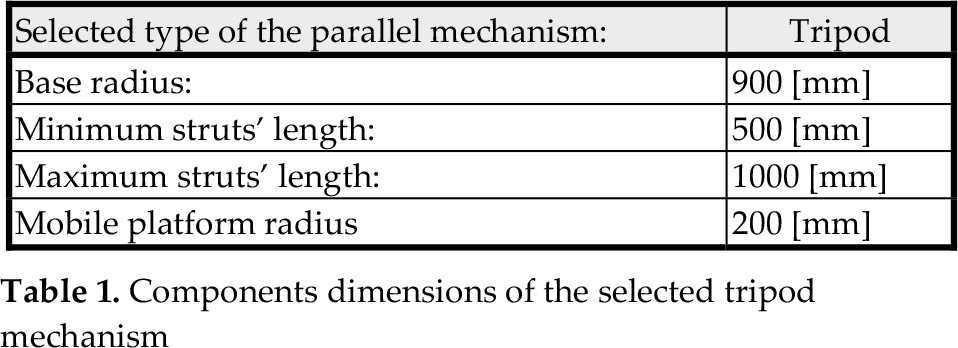
The turbine impeller is a complex geometric shape of dimensions Ø252×100mm after modelling and discretization of the model with isoparametric, triangular finite elements approximated with 1682 surface finite elements, that is, 3364 nodes. On the basis of the ratio between the overall dimensions and regularities defined in Section 2.3.2, the tripod type parallel mechanism was selected in the processor of the “Parallel mechanism” program. According to the turbine impeller dimensions, based on the criteria from Section 2.3.1, preliminary dimensions of the parallel mechanism have been calculated and the real dimensions of components have been selected from the database. Table 1 shows the overall dimensions of the parallel mechanism components and Figure 20 shows the model of the turbine impeller in the workspace of the selected mechanism.
Components dimensions of the selected tripod mechanism
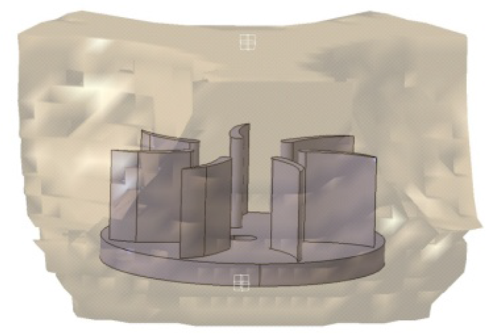
Turbine impeller in the workspace of the selected tripod mechanism
The second model of the endoprosthesis body of the hip joint with dimensions of 187×54×23mm is upon pre-processing described by 904 finite elements (1810 nodes). On the basis of the selection criteria for the mechanism type, the triaglide mechanism was selected in the processor. As in the previous case, according to the dimensions of the endoprosthesis body, the parallel mechanism dimensions have been calculated and the real components' dimensions adopted. Table 2 shows the main dimensions of the parallel mechanism components and Figure 21 shows the endoprosthesis model in the workspace of the selected mechanism.
Components dimensions of the selected triaglide mechanism
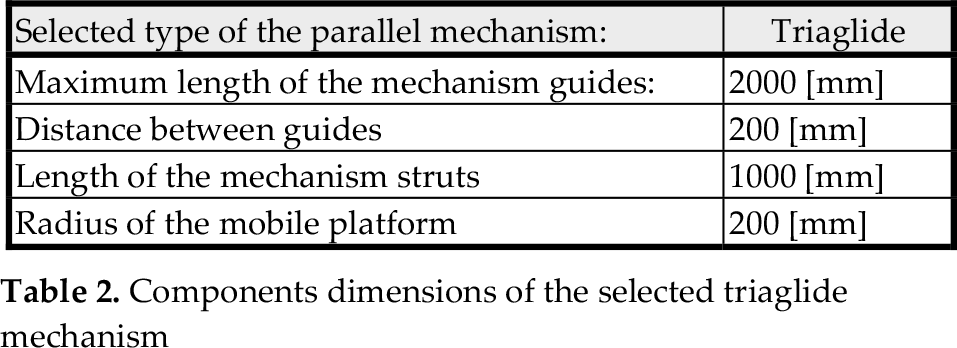

Endoprosthesis model in the workspace of the triaglide mechanism
During the verification of single subsystems and program suite modules and in the course of this process, no irregularities that could be expected in the formation of assemblies have been observed and the mechanisms of minimum dimensions with the coefficient of the workspace occupancy have been obtained, that is, Cfw=0.2 (in tripod) and Cfw=0.1 (in triglide mechanism). Furthermore, the component dimensions of the existing machine tools and robots have been adopted from the database.
Figure 22a shows as follows: the tripod mechanism model resulting from the process of designing of the machine tool used for the turbine impeller processing and the triaglide mechanism developed in the process of designing the machine tool used for the construction of the hip endoprosthesis (Figure 22b).
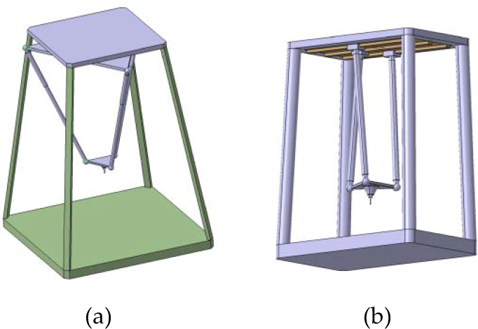
Models of machine tools' mechanical structure developed in the process of designing of the turbine impeller (a) and the hip endoprosthesis (b)
5. Discussion
The tasks included in this research, segments of which have been described in this paper, can be divided into a number of units: the workspace analysis and establishing the designing criteria, as well as defining the program suite for the automated design of parallel mechanism-based robots and machine tools.
The first part of the research, “analysis of workspaces”, is to determine the workspace characteristics of parallel mechanism-based robots and machine tools. In order to accomplish this task, it is necessary to undertake a number of inverse kinematics-based analyses of different types of parallel mechanisms. From a mathematical point of view, this is a complex problem, especially if we aim for a universal solution. For the purpose of this research, the software “Workspace” was developed, which applies the methods of analysis of kinematic properties of parallel mechanisms based on continuum discretization. The software structure was set on modular principles, which enable its partial upgrading. In this phase the analysis of the three mechanism types (tripod, triaglide and ortoglide) was undertaken with around 240 dimension variations. On the basis of the workspace shape and volume of the analysed mechanisms, the parameters relevant for the creation of the workspace have been defined. In addition, the analyses were undertaken that provide the basis for the establishment of the criteria for selection of the parallel mechanism type and components, as well as the optimization of the resulting solution. The application of the software “Workspace” ensured that, besides the required geometric properties of the workspace, its visual computer model is developed as well as the discrete mathematical description in the form of coordinates' matrix. Further development of “Workspace” software includes improvement of the structure in terms of definition and other interpretations of the workspace [11]. The overall workspace, defined by the software in the current phase of development, does not provide full insight into the applicability of the parallel mechanism.
The second part of the research is focused on setting the decision-making criteria necessary for automated design of parallel mechanism-based machine tools or robots. This is based on the results of the workspace analysis by the application of adequate mathematical methods. This research resulted in the establishment of a number of criteria, which may be classified into three groups:
Criteria resulting from the overall dimensions and volume of the workspace, which are used in the selection of the parallel mechanism type
Criteria concerning the workspace shape, which in this case facilitates selection of the parallel mechanism components and optimization of the resulting solution
Additional criteria, established on the basis of exploitation and the user's requirements.
The conducted research points to the fact that, due to complexity of the workspace, it is not possible to establish universal criteria applicable in all phases of the robots and machine tools designing process. Consequently, it was necessary to establish multi-criteria decision-making processes, which is particularly evident in the phase of optimization of the obtained solution. The criteria specified in the paper present the selected segment of the workspace analysis results, which also included the effects of the parallel mechanism base dimensions on the workspace, properties of the used joints etc. They are subject to the applicability analysis for different areas of application of the designed mechanism.
In the third phase the concept of the program suite for the automated design of parallel mechanism-based machine tools has been defined, which is based on modular principles. As a result, the programme suite “Parallel mechanism” was developed and verified using a number of examples. It is necessary to improve the implemented program suite in the course of further research, first of all in the segment of optimization of the obtained parallel mechanism by introducing multi-criteria analyses along with the application of artificial intelligence elements. Currently, the implemented method of comparison with the existing machine tools and robots is not satisfactory.
According to the results of the verification process, it may be concluded that the program suite “Parallel mechanism” enables automation of the design process of parallel mechanism-based machine tools. Furthermore, it is necessary to point out that the described methodology includes only characteristics of the workspace formed by the parallel mechanism, which is only one of many possible approaches to the design process.
6. Closing considerations
Robots and machine tools with a kinematic structure based on parallel mechanisms are the result of evolution of industrial means of production, encouraged by demands for increased speed and accuracy of manipulation, as well as other exploitation factors.
The previous development of parallel-mechanism based robots and machine tools followed two courses. The first course of development is aimed at improvement of the parallel mechanism structure with a view to mitigation of detected weaknesses and improvement of their strengths in relation to serial mechanisms. As a result, a great number of parallel mechanisms have been developed so far, from plane parallel mechanisms over three-axis ones, to kinematic and structurally complex ones with six degrees of freedom. The second course of improvement is focused on the development of design methods for robots and machine tools, which take into account all the characteristic properties of parallel mechanisms and in specific segments enable the automation of this process.
The paper describes a method for conceptual design and selection of components of parallel mechanism-based robots and machine tools on the basis of geometry of their future work piece. This method is based on the comparison of computer models of work pieces and the workspace characteristics formed by specific types of parallel mechanisms. In this way, designers are able to have insight into one of important characteristics of a future machine in an automated regime, which facilitates a decision-making process in the course of its design.