
Abstract
A novel parallel mechanism of two translations and one rotation freedom degrees two-prismatic joint-cylindrical joint-one-cylindrical joint-prismatic joint-revolute joint (2PC-CPR) is proposed. The mechanism can be applied to write Chinese characters and to classify productions with the appropriated control. In this article, the kinematics and dynamics analysis are systematically conducted with the following procedure. First of all, the 2PC-CPR parallel mechanism is designed by GF set and the freedom degree of the mechanism is calculated using screw theory. Then the formula for solving the inverse/forward displacement, velocity, and acceleration is derived based on the geometrical constraints. The dynamics model is established by using virtual work principle. Finally, kinematics SimMechanics model is created by the co-simulation of SolidWorks and MATLAB software, and its workspace is analyzed.
Introduction
Parallel robots with three freedom degrees have the advantages such as simple structure, low cost, highly targeted. It has a broad application prospect in the fields of parallel robot. Some parallel mechanisms with three translation freedom degrees have drawn significant attention by researchers these years. Tsai 1 invented a parallel mechanism of three-universal hinge-prismatic joint-universal hinge(3-UPU), and it is studied by many scholars later. 2 –6 Carricato and Parenti-Castelli 7,8 proposed and analyzed a series of isotropic three-translational parallel mechanisms. Kong 9 proposed a parallel mechanism of three-cylindrical joint-revolute joint-revolute joint (3-CRR), and its kinematics and singular problem were analyzed. Li 10 researched a novel parallel mechanism of three-prismatic joint-revolute joint and cylindrical joint (3-PRC) with over constraints. Ruggiu 11 presented a translational parallel mechanism of three-cylindrical joint-universal hinge-revolute joint (3-CUR) and analyzed its kinematics. Kim 12 proposed the sufficient and necessary conditions of constituting a three-translational parallel mechanism. Some parallel mechanisms with three rotation freedom degrees were also investigated. Gosselin 13 proposed a type of parallel mechanism with three rotation freedom degrees, and its singular pose was analyzed. Karouia and Hervé 14 proposed a kind of pure rotation 3-UPU parallel mechanism and Di Gregorio 15 researched its singular and static problems. Besides, Huang 16 integrated some different 3-UPU parallel mechanism and analyzed their kinematics characteristics. Lu and Hu 17 constructed a type of parallel mechanisms of two-universal hinge-prismatic joint-universal hinge plus X joint (2UPU+X). Research of the mechanism with three freedom degrees is mainly focused on the symmetric mechanism with pure rotation or pure translation. The type of asymmetric parallel mechanisms with one translation and two rotations or two translations and one rotation has been in the lack of investigation. However, the requirement for novel asymmetric parallel mechanism with three freedom degrees will gradually increase with the application of the robot in various fields.
To meet the increasing need in the robot field, a novel 2PC-CPR parallel mechanism is proposed and the following works are done in this article. A novel 2PC-CPR parallel mechanism with two translations and one rotation is designed using GF
set. The mechanism can be applied to write Chinese characters and classify products. The freedom degree of the mechanism is calculated with screw theory. The formula for solving the inverse/forward displacement kinematics, velocity, and acceleration is derived. The dynamics model is established. The SimMechanics model of kinematics is created by the co-simulation of SolidWorks and MATLAB to verify the correctness of theoretical derivations. The workspace is analyzed.
Design of 2T1R parallel mechanism and its freedom degrees
The establishment of 2T1R parallel mechanism
To obtain a two translations and one rotation (2T1R) parallel mechanism, GF set is selected as the method to synthesize the mechanism. GF set is used to describe the motion features of the robot mechanism end. All the freedom degrees of the robot mechanism end include three translations and three rotations. Then the mechanism end definition in GF sets can be expressed as follows 18,19

where Ta , Tb , and Tc denote three translations of the mechanism end, subscript a, b, and c denote three noncoplanar movement direction vectors; Rα , R β , and Rγ denote the three rotations of the mechanism end; subscript α, β, and γ denote three noncoplanar rotation direction vectors.
The motion characteristics of the robot mechanism can be qualitatively described by each item of the GF set. GF set can be classified into seven categories according to the number of the dimension, which is shown in Table 1.
Classification of GF sets.

As the configuration synthesis of GF
set, we can obtain the novel 2PC-CPR parallel mechanism with the following steps. Step 1: Design a three-degree freedom parallel mechanism with 2T1R, the motion feature can be described by GF
set as: GF
= (Ta Tb
0; Ra
0 0).Where Ta represents the translation along the direction of a, Tb represents the translation along the direction of b, and Rα represents the rotation around the direction α. Step 2: Determine the number of kinematic branch. For the input number of the mechanism is equal to number of the degree of freedom, the mechanism has three kinematic branches. Step 3: Determine the type of kinematic branches as two 2T1R branches and a 3T1R branch. Then the three branches are denoted as: GF
1 = (Ta
1 Tb
1 0; Ra
1 0 0), GF
2 = (Ta
2 Tb
2 0; Ra
2 0 0), and G
F3 = (T
a3 T
b3 T
c3; R
a3 0 0) in GF
set. Then we can obtain the mechanism with three freedom degrees by intersection rule GF
= GF
1 ∩ GF
2 ∩ GF
3 = (Ta Tb
0; Ra
0 0). The intersection of three kinematic branches is shown in Figure 1. Step 4: Determine the kinematic pairs on kinematic branches. The first and the second kinematic branches can be made of a sliding pair and a cylindrical pair, and the third kinematic branch can be made of a cylindrical pair, a sliding pair, and a revolute pair. Step 5: Determine the spatial position relationship. The translation plane of the two 2T1R kinematic branches is parallel and the rotation axis is coincident; the rotation axis of 2T1R kinematic branch is parallel with the rotation axis of 3T1R kinematic branch. Then the three-dimensional model is constructed in Figure 2.

The intersection of three kinematic chains.

The three-dimensional model of 2PC-CPR parallel mechanism.
The DOF of 2PC-CPR parallel mechanism
According to the modified Grübler–Kutzbach criterion, 20 the degree of freedom can be calculated by the equation as follows

where d is the order of a mechanism and related to common constraint, n is the number of components include the frame, g is the number of kinematic pair, fi is the degree of freedom of the i kinematic pair, and v is the redundant constraint for parallel mechanism.
Screw theory is introduced to describe the constraints in single kinematic branch, and then all branch constraints are synthesized to calculate the corresponding degrees of freedom according to equation (2). A screw can be expressed as equation (3). All the components of a screw is shown in Figure 3
The components of a screw.
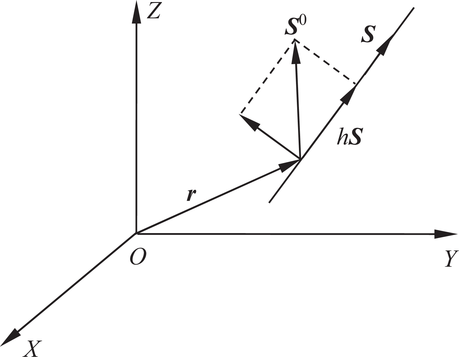
According to the value of h, two types of special screw can be expressed as

Two screws are denoted as

where the symbol ∘ denotes the reciprocal product of two screws.
If the reciprocal product is

where
To obtain the common constraints in equation (2), two local coordinate systems o
1
x
1
y
1
z
1 and o
2
x
2
y
2
z
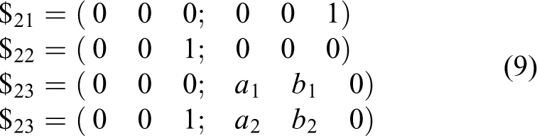
2 are established on two kinematic branches, respectively. The global coordinate system OXYZ is established on the base. All the kinematic screws of the PC and CPR branches are shown in Figure 4. In the first kinematic branch, the sliding pair is denoted by the kinematic screw $11. And the cylindrical pair is denoted by the two screws $12 and $13. According to equation (4), the screw system of the first kinematic branch is expressed as follows
The kinematic screws of PC and CPR branches.

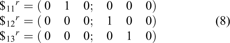
The constraint screw system includes a force line vector and two moments. The translation along y-axis is constrained by the force, and the rotations around x-axis and y-axis are constrained by the two moments.
Similarly, the screw system of the second kinematic branch is as follows
The kinematic screw system is composed of four independent screws, then the constraint screws are as follows
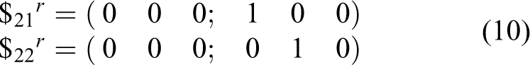
The constraint screw system includes two moments, which constrains the rotations around x-axis and y-axis.
Then the mechanism has two common constraints and zero redundant constraint. The degree of freedom can be obtained according to equation (2)

Therefore, the freedom degree of the mechanism is 3, which are translations along the x-axis and z-axis, and rotations around z-axis.
The kinematic analysis
Inverse solution for displacement
The coordinate system oxyz is established on the upper platform in Figure 5. The vector coordinates of structure parameters is shown in Table 2.

The hinge coordinates of the 2PC-CPR parallel mechanism.
The structure parameter coordinates.

The terminal position and orientation of the moving platform is denoted as

The coordinate of the hinge point in the moving coordinate system is denoted as

where


The hinge point coordinates.


Then the inverse solution equation of displacement can be obtained as follows

where
Forward solution for displacement
In the forward solution of displacement, x, z, and γ should be obtained according to z 1, z 2, and ϕ. From equation (17), we can obtain the forward solution equation of displacement as follows

Inverse velocity analysis
The relationship between input and output displacement is given in equation (18). By differentiation of equation (18) with respect to time, the relationship between the input speed and output velocity is derived as follows

Matrix form of equation (19) can be expressed as

where
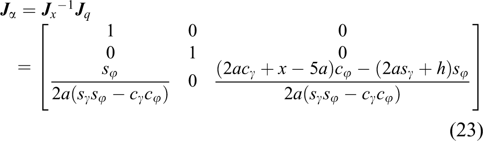
Forward velocity analysis and Jacobian matrix
equation (19) can also be written as follows

where
If

where
Then the Jacobian matrix
Acceleration analysis
By differentiation of equation (19) with respect to time, the relationship between the input and output acceleration is derived as

Matrix form of equation (24) can be written as

where
The dynamics model
According to the virtual work principle, 22,23 the sum of the virtual work generated by the arbitrary virtual displacement is zero. Then virtual work generated by the joint space virtual displacement is equal to the virtual work generated by the virtual displacement of operating space. It can be expressed as equation (26)

where τ is the force or torque vector of each joint, δ
The relationship of the virtual displacements

Substitute equation (27) into equation (26), we can obtain the equation (28)

The establishment of dynamic model
For the parallel mechanism, the driving force from the PC and CPR drive branch should be balanced with the equivalent driving force transformed from moving platform. Then the dynamic model is established as follows

where
The influence of friction is not considered, and the bar mass center is simplified to the geometric center. Combining equation (28) and equation (29), the equivalent driving force can be expressed as follows

where
The calculation of the force and torque
According to Newton’s second law and Lagrangian equation, the parameters
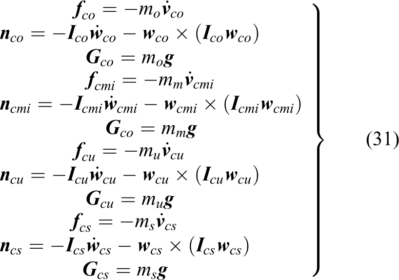
where mo and
The calculation of Jacobian matrix
(1) Jacobian matrix between moving platform and drive components
Suppose that the point o is the mass center of moving platform, then the velocity relationship between point o and drive components is obtained by equation (22). And then the Jacobian matrix between moving platform and drive components is
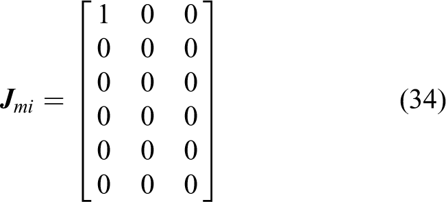
(2) Jacobian matrix between the PC branch and drive components
In the fixed coordinate system, the velocity of PC branch mass center is set as

The mass center of PC component is on B 2 B 5, and the centroid coordinates is denoted as(0, m, 3a). Then the position and orientation of PC component mass center can be expressed as follows

By differentiation of equation (33) with respect to time, the Jacobian matrix
(3) Jacobian matrix between the CPR branch and drive components
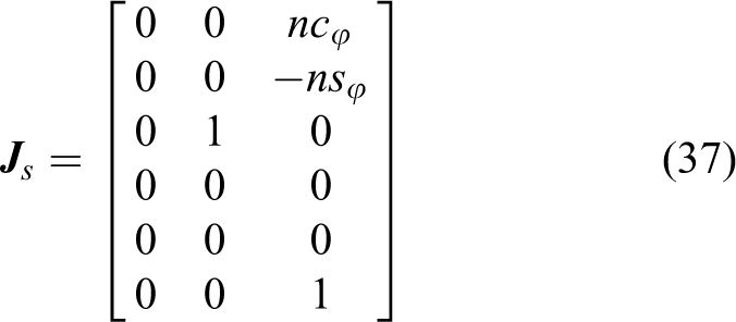
The driver branch is divided into telescopic swinging rod and rotary rod. In the fixed coordinate system, the mass center velocity of telescopic swinging rod is set as

The mass center of telescopic swinging rod is on B 3 B 6, and the centroid coordinates is denoted as(5a, n, 0). Then the position and orientation of telescopic swinging rod mass center can be expressed as follows

By differentiation of equation (36) with respect to time, the Jacobian matrix
The mass center of rotary rod is on b 3 B 6, and the distance between the centroid and b 3 is denoted as l. Then the position and orientation of rotary rod mass center can be expressed as follows

By differentiation of equation (38) with respect to time, the Jacobian matrix

where
Then the driving force τ can be obtained if the external force
Kinematics simulation
Combining SolidWorks and MATLAB software, SimMechanics model is established in Figure 6. The physical environment parameters are set as kinematics. Three driver modules and a sensor measurement module are added to the SimMechanics model. Subsystem1, Subsystem2, and Subsystem3 in Figure 6 are package subsystems as Figure 7(a), (b), and (c), respectively.

The kinematics model in SimMechanics. (a) Subsystem1, (b) Subsystem2, and (c) Subsystem3.

The package subsystems.
For the parameters in Tables 2 and 3, a and h are set as 20 mm and 36 mm, respectively. z1, ϕ and z2 are changed according to ramp signal as Figure 8(a). The theory values of forward displacement solution in equation (18) can be expressed as the solid line in Figure 8(b). The position and posture of point o are obtained and shown as the dotted line in Figure 8(b). Therefore, the correctness of theoretical forward displacement solution of the parallel mechanism is verified.

The kinematics simulation result. (a) Three initial inputs; (b) comparison of the theory and simulation value.
Workspace analysis
In the kinematics SimMechanics model, the three ramp function inputs are changed. Then the workspace of mechanism can be acquired. Specific steps are as follows: Step 1: Set the three input values range as z
1 = (−15∼10) m, z
2 = (−20∼20) m, Step 2: Set z
1 = −15 + iδ1, z
2 = −20 + Step 3: When i = 0, 1, … , n, the data of step 2 are measured and saved. Step 4: Set z
1 = −15 + Step 5: When i = 0, 1,…, n, the data of step 4 are measured and saved. Step 6: Set z
1 = −15 + Step 7: When i = 0, 1, … , n, the data of step 6 are measured and saved. Save all data to sj.txt file, and MATLAB program is edited as follows: clear all clc importdata(‘e:\sj.txt’); x=ans(:,1); y=ans(:,2); z=ans(:,3); [xx, yy]=meshgrid(-47:-25,-18:-22); zz=griddata(x, y, z, xx, yy.’v4’); surf(xx, yy, zz); shading interp;
These points are shown in a three-dimensional coordinate, then the workspace of the mechanism is obtained in Figure 9.

The workspace of 2PC-CPR parallel mechanism.
According to the workspace, the mechanism can be used to write Chinese characters such as “中” when a pen is installed at the center of moving platform. Besides, it can also be applied to productions classification, and so on.
Conclusion
In this article, a novel 2PC-CPR parallel mechanism is presented. The degree of freedom, kinematics analysis, dynamic model, SimMechanics model, and workspace of the parallel mechanism were investigated. We have come up with the following conclusions. The freedom degree of the parallel mechanism turns out to be three according to the screw theory, which proves that the parallel mechanism is reasonable. The input and output relationships of displacement, velocity, and acceleration are obtained by kinematics analysis. The Jacobian matrix is calculated out. The dynamic model is derived based on the virtual work principle, which presents the foundation for the control system. The kinematics SimMechanics model is established. Simulation results verify the theoretical derivations. The workspace of the parallel mechanism is analyzed based on kinematics SimMechanics model, and it can be imagined that our newly built mechanism has a promising future in the application of robot field.
Footnotes
Declaration of Conflicting Interests
The author(s) declared no potential conflicts of interest with respect to the research, authorship, and/or publication of this article.
Funding
The author(s) disclosed receipt of the following financial support for the research, authorship, and/or publication of this article: This work was financially supported in part by National Natural Science Foundation of China (no. 51105050).