
Abstract
This paper provides a kinematic and dynamic analysis of mobile parallel manipulators (MPM). The study is conducted on a composed multi-degree of freedom (DOF) parallel robot carried by a wheeled mobile platform. Both positional and differential kinematics problems for the hybrid structure are solved, and the redundancy problem is solved using joint limit secondary criterion-based generalized-pseudo-inverse. A minimum time trajectory parameterization is obtained via cycloidal profile to initialize multi-objective trajectory planning of the MPM. Considered objectives include time energy minimization redundancy resolution and singularity avoidance. Simulation results illustrating the effectiveness of the proposed approach are presented and discussed.
Keywords
1. Introduction
1.1 Motivation
A mobile parallel manipulator consists of a mobile platform carrying a parallel manipulator. Mobile robots have wide applications in such areas as automatic material handling in warehouses, transportation and health care in hospitals, and exploration in hazardous environments. Because of their high accuracy, velocity, stiffness, and payload capacity the progress of parallel robots (PRs) is accelerated since PRs outperform their serial counterparts [1]. However, the main drawback of PRs is their limited workspace, which restricts their applications [2]. Recently, many researchers have proposed parallel mobile robot design mechanisms [3–7]. Since an MPM possesses the advantages of both a mobile robot and a parallel robot, it is a potential competitor in extensive applications where high accuracy operation, a high rigidity and payload capacity are required, such as in autonomous guidance vehicles and personal robots, and space and underwater robotics.
1.2 Related Works
A literature survey on mobile parallel robots reveals that parallel mobile robots remain a hot area of research. Yamawaki et al. proposed a self-reconfigurable parallel robot, which can be configured to 4R and 5R closed kinematic chains [4]. They proposed a parallel mechanism mobile robot mounted on a crawler mechanism. The combined mobile robot can gain some useful functionalities besides locomotion from the advantage of its parallel mechanism. For example it may be able to traverse a hump by controlling its centre of gravity, carrying an object by making use of its shape. The same study analysed the motions of these functionalities and verified them experimentally with real robots. Graf and Dillmann [5] proposed the use of a Stewart platform mounted on a mobile platform to compensate the unwanted accelerations. The necessary movement of the platform is calculated by a so-called washout filter. This combination can be applied either in the transport of liquids in open boxes or in medical transport, where patients must not be affected by any acceleration. Decker et al. implemented and compared several different approaches for the motion planning of the Gough-Stewart Platform mounted on a mobile robot[6]. They aimed to enhance the capabilities of transport vehicles to enable them to carry delicate objects of various shapes and sizes without requiring extensive packaging to protect them. Li et al. proposed a novel design and modelling of mobile parallel manipulators (MPM) [15]. An MPM composed of a three-wheeled nonholonomic mobile carrier and a 3-RRPaR translational parallel platform is designed and investigated in detail. The position kinematics solutions are derived and the Jacobian matrix relating output velocities to the actuated joint rates is generated. In [6] and [7] a combination of a mobile robot and a Stewart platform is proposed for active acceleration compensation to enable the smooth transport of objects. In [8], a mobile parallel manipulator (MPM) is proposed using the combination of a wheeled mobile platform and a parallel manipulator, which provides extra mobility to the robotic system, enlarging the effective workspace of the parallel manipulator while retaining its advantages. MPMskeepthe advantages of both the mobile and the parallel robot. The MPM is a potential competitor in applications where high-accuracy operation and high rigidity and payload capacity are required, for example in autonomous guidance vehicles or personal robots. Nevertheless, the integration of a parallel manipulator and a mobile robot induces a large number of challenging difficulties, since in most cases the mobile robot is subjected to nonholonomic constraints and the parallel robot introduces many complex kinematic constraints. These difficulties include how to establish the dynamic model of the hybrid system in a systematic way, which involves redundancy resolution and singularity avoidance and often performance indicators of the controller motion. The optimal control and multi-objective trajectory planning of robotic systems is a dynamic research area [9–19]. The present paper extends the application of optimal control and multi-objective decision making to constrained time-energy trajectory planning of mobile parallel manipulators.
The remainder of this paper is organized as follows. Section 2 explains in detail the kinematic modelling. In Section 3 the dynamic modelling of the hybrid system is performedusing the Lagrange method. The redundancy resolution is achieved through joint limits and singularity avoidance. A model multi-objective motion is then carried out for the MPM in Section 4. In Section 5, the ANFIS-based planning in developed. Simulations illustrating the effectiveness of the proposal are presented in Section 6. Finally, Section 7 concludes the paper.
2. Kinematic Modelling and Analysis
2.1 Architecture Description
Research into mobile parallel manipulators is a relatively new research domain, and substantial literature has recently been published [18–23]. In this paper we use the architecture presented in [2], which consists of a three-wheeled nonholonomic mobile robot and a modified 4-DOF MPM version of a DELTA parallel robot (Fig.1). Figure 2 presents the schematic diagram of the designed MPR. R and Pa stand for the revolute and parallelogram joints, respectively [2].

The mobile parallel manipulator [2]

Schematic representation of the MPR [2]
2.2 Position Kinematics Analysis
From Figure 2, we can obtain the following:

Where c stands for cosine, s stands for sine, r is the radius of each driving wheel, and θL and θr denote respectively the rotating angles of the left and right driving wheels. Let ξ =[xm ym φmθL θr]T be the general coordinates of the mobile platform. The forward kinematics problem is very complex for a parallel robot, although the inverse kinematics problem is extremely straightforward in general [10].
Assuming that (νm) is the linear and (ωm) the angular velocity of the mobile platform and the actuated inputs of the actuators (θi, i =1, 2, 3), the position (x, y, z) and orientation (ϕ) of the mobile platform are solved using the forward kinematics.
Assume that the wheels of mobile platform have no slip in the forward, reverse, or sideways directions. Let Δt → 0; the velocities during this time interval can be considered as a constant (see Fig. 2b).
Let
In frame B, let
B


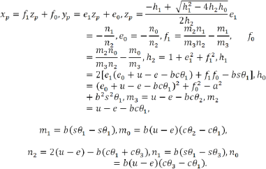
Using Maple (the computer algebra software system) and making some substitutions, solving (2)–(4) leads to solutions for the forward kinematics of the parallel robot:

Where

The position of the moving platform can be derived by:

where

and

is the rotation matrix of the moving frame B with respect to the fixed frame O.
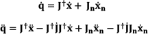
2.2 Differential Kinematics Analysis
Let

Additionally, let

where the 3×3 forward and inverse Jacobean matrices

The detailed expressions of aij and bijappear in the appendix.
When the parallel robot is away from the singularity, from (10) we can obtain

where
Substituting (7), (8) and (12) into (9), and considering (1), we obtain:

The matrix
Differentiating (13) with respect to time yields

In addition, solving (13) leads to

where
2.3 Redundancy Resolution through Joint Limits Avoidance
To include a secondary task criterion by a performance index g(

Where:

The related criterion to avoid the singularity is to maximize the manipulability; we choose q̇s as follows:

where
Now, the formula of the augmented function to avoid singularity and joint limits is as follows:

3. Constraints and Dynamics Modelling
3.1 Constraint Equations:
The mobile robot cannot move in the lateral direction, and the three constraints for the mobile platform can be represented by (2). From (3) and (4), we can derive another three constraint equations for the MPM:

3.2 Dynamic Equations:
All the dynamic equations are taken from [8], and are re-derived here for quick reference. The Lagrange function for the MPM becomes

The constrained dynamics for the entire system of the MPM can be determined by

where ζ = [ξT θ1 θ2θ3 xy z]
T
is the generalized coordinates and
Now substitute xp and yp in (5) and solve for zp; solving Eq. 6 and Eq. 7 leads to solutions for the forward kinematics of the parallel robot:
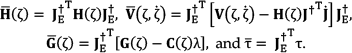
Solving the augmented Lagrange equation gives:

where i=1, 2, 3, …, 11
H(ζ) = diag([A1, A2, A4, A7, A10]) ∈ ℜ5×5 is the symmetrical and positive definite inertial matrix.

G(ζ) = [0; 0; A5; A11] ∈ ℜ5×1 represents the vector of gravity forces,

Then, the actuated torques τ = [τl, τr τ1τ2τ3] T can be solved from the second set of equations of (28) for j = 4, 5, 6, 7, and 8, which can be written into a matrix form:

where
Differentiating (17) with respect to time yields

Let


When
Defining

Where
4. Multi-Objective Motion Planning
4.1 Constrained Linear-Decoupled Form
Here, we use the same approach used by Khoukhi et al. [16]. The major computational difficulty in this system cannot be solved with the original non-linear formulation. Instead, it is solved using a linear-decoupled formulation.
Theorem:
Provided that the inertia matrix is invertible, then the control law in the Cartesian space is defined as:

This leads the robot to have a linear and decoupled behaviour with the dynamic equation:

where
This follows simply by substituting the proposed control law (39) into the dynamic model (34), obtaining:

Since
This gives the robot the decoupled and linear behaviour described by the following linear dynamic equation, written in discrete form as:

where
Notice that the non-linearity is transferred to the objective function. One problem with this formula is the lack of accuracy of the Euler's method. In order to improve the accuracy, and because the MPM structure contains highly nonlinear equations as shown in the previous chapters, we use the Adams-Bashforth Formula:

Applying the Adams-Bashforth Formula (42) gives:


Since it is difficult to obtain the derivative of


Now, the decoupled formulation transforms the discrete optimal control problem into optimal sequences of sampling periods and acceleration inputs

The above-mentioned constraints remain the same, except actuator torques, which become:

Henceforth, inequality constraints g3 and g4 are rewritten as:


Similarly to the non-decoupled case, the decoupled problem might be written in the following form:

subject to

4.2 Augmented Lagrangian Formulation
We used the same approach as [24]. Now, the augmented Lagrangian is associated to the decoupled formulation (P) as follows:
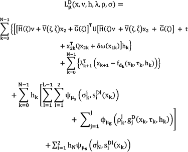
where the function
The first-order Karush-Kuhn-Tucker optimality necessary conditions require that for
The co-states

The gradient of the Lagrangian with respect to sampling period variables is:

The gradient with respect to acceleration variables is:

where

In the previous equations
5. AL-ANFIS Based Motion Planning
5.1 AL-ANFISSet up
Based on the result of the AL solution, an ANFIS-based structure is built to solve the online trajectory planning of the MPM. In [11, 23–24], an ANFIS-based inverse kinematic solver was proposed. In this paper we extend this principle to multi-objective planning, including plate-form dynamic, torques and other technological constraints, in order to build an online ANFIS Planner. Both offline and online planners show that the trajectory planning of MPM is derived with small, acceptable error. A set of derivatives of (q1, q2, q3, q4, q5) is used to construct the true derivatives (x, y, z, ϕ, xn), and thus to obtain an error on which to apply the back-propagation algorithm. As mentioned above, here we add ẋn related to q̇s from equation (15) to remove the redundancy of the system.
5.2 AL-ANFISNeuro-Fuzzy Inverse Planning
AL-ANFIS is a multi-layer feedforward adaptive network. The first layer is a two-input layer, characterizing the Cartesian position crisp values. The last layer is a three-outputlayer characterizing the corresponding crisp joint values (Figure 3). AL-ANFIS involves three hidden layers. The first is the fuzzification layer, which transfers the crisp inputs to linguistic variables through sigmoidal transfer functions. The second is the rule layer, which applies the product t-norm to produce the firing strengths of each rule. This is followed by a normalization layer. The training rule option is the Levenberg–Marquard version of the gradient back-propagation algorithm. This choice allows the learning process to be speeded up substantially with less iteration compared to standard back-propagation (e.g., gradient descent).
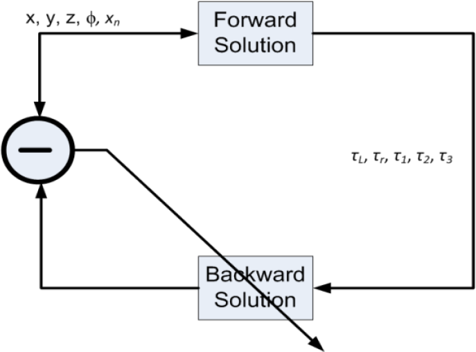
AL-ANFIS Solution learning module
6. Simulation Results
The algorithm described in the previous section is built using Matlab software. The following simulation figures show different scenarios of minimizing time, energy, and both together. In time minimization, the energy weight is reduced to zero, and the same is done for energy minimization. For both time and energy minimizations the weight is set to 1. The following simulation figures show different scenarios of minimizing time, energy, and both together.
All the following simulation cases are performed for the initial values of theta are as follows:

And the target values of thetas are:

6.1 Initial solution
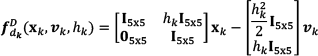
To secure the convergence of the AL algorithm – even though it converges even if it starts from an unfeasible solution – a kinematically feasible solution is defined, based on an optimal time trajectory parameterization. The initial time steps are assumed on an equidistant grid, for convenience:

Upon this parameterized minimum time trajectory, a predictive planning model is built in order to achieve a good initial solution for the AL.
To calculate the inertia matrix and the Coriolis and centrifugal dynamics components, we can use the approach developed initially for serial robots by Walker and Orin [25] based on the application of the Newton-Euler model of the robot dynamics. This method is straightforward and generallyapplicable to the case of MPM robots.
6.2 Search Direction Update
A limited-memory quasi-Newton method is used at each iteration of the optimization process to find the solution for the minimization step at the AL primal level, because the considered problem is of a large scale. In this research a systematic procedure similar to that used in [16] is used in the augmented Lagrangian implementation.
6.3 Simulated Scenario 1: Minimizing Time
Below are shown theseparate results of the minimization of time alone, energy alone, and both time and energy. Figures 4 to 7 show the simulated scenarios for minimizing time. Figures 8 to 11 show the simulated scenarios for minimizing energy. Figures 12 to 14 show the simulated scenarios for minimizing time and energy.

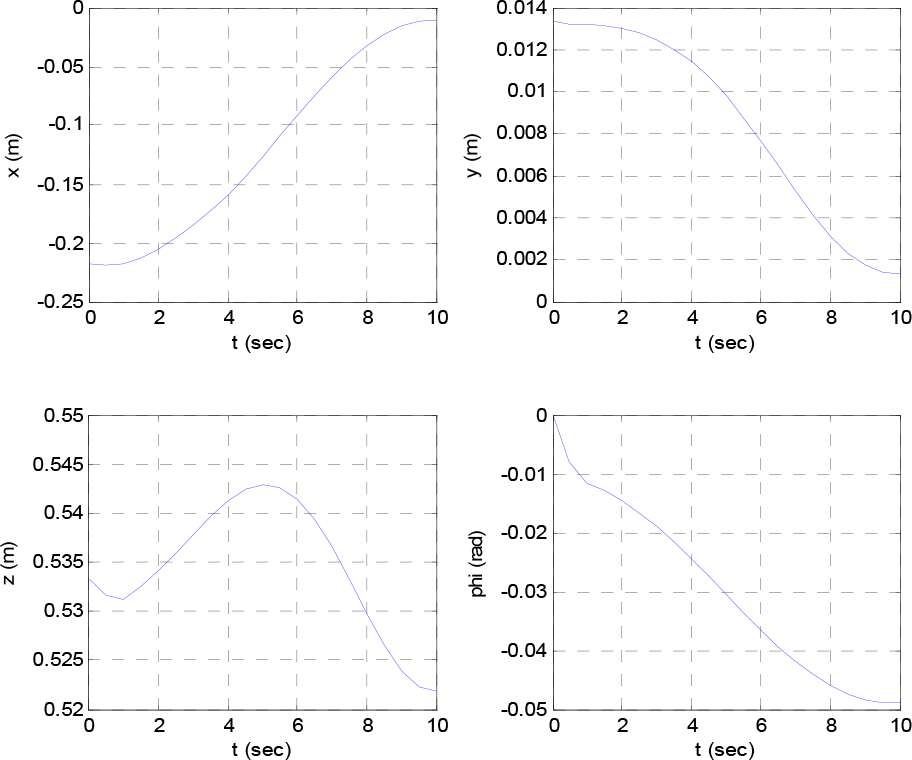
Variations of the end effector position due to minimization of time
Figure 4 shows the variations of the end effector position due to minimization of time, and Figure 5 shows variations in the end effector position due to minimization of time. It also shows the variation of torque during the interval, and the variation of time steps along the path (Fig.6).

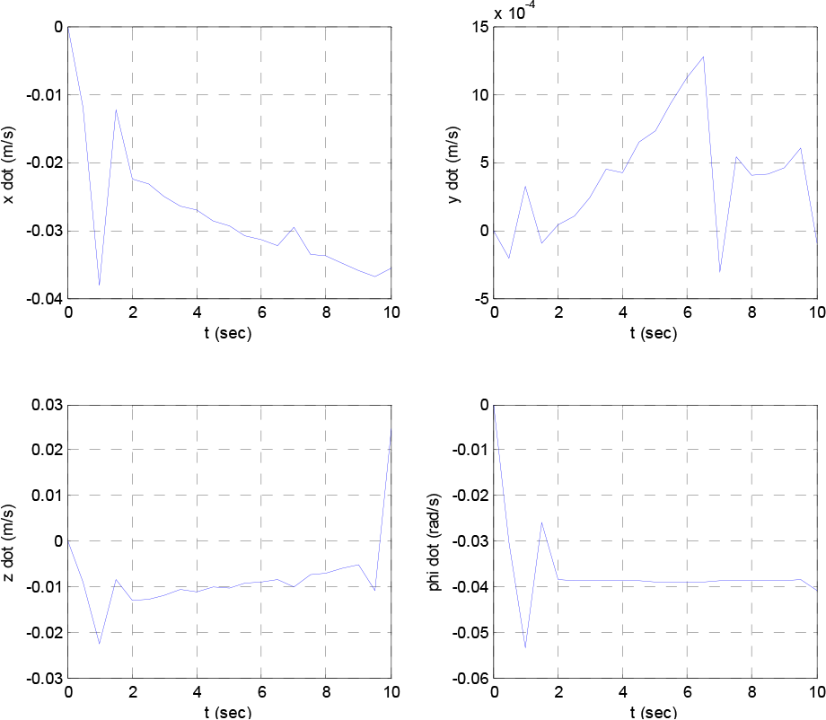
Variations of the end effector velocity due to minimization of time

Variations of the torque due to minimization of time
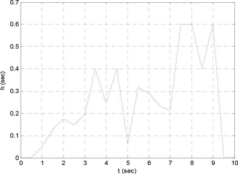
Variations of the time steps due to minimization of time
All the figures show that the minimization of both h and v gives a result close to the desired values, with acceptably small error. Moreover, the theta figures differences between the desired values and the values achieved, which are very close to the target points.
6.4 Simulated Scenario 2: Minimizing Energy
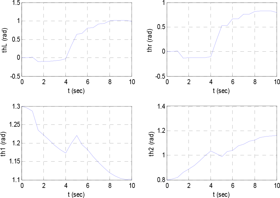
Variations of the angles due to minimization of energy
Variations of the end effector position due to minimization of energy
Variations of the end effector velocity due to minimization of energy

Variations of the torque due to minimization of energy

Variations of the angles due to minimization of both time and energy

Variations of the time step due to minimization of both time and energy

Variations of the end effector velocity due to minimization of both time and energy

Variations of the torque due to minimization of both time and energy
6.5 Simulated Scenario 3: Minimizing time and energy
AL-ANFIS is a structure built using the Fuzzy Logic Toolbox in the Matlab software, which is used to construct an online trajectory plan (Fig. 3). The result of the offline trajectory planning is used to run 400 different trajectories; each one contains 20 points along the trajectory. This gives 8000 samples, among which 750 are considered for training; testing and validation are achieved using 400 entry samples.
Figure 16 shows the training performance for AL-ANFIS, which is interesting as it achieves a very small root mean square error (RMSE), less than 0.1 in less than 10 epochs. It should be noted that the configuration used for the learning is one among infinite possible solutions for each input. Figure 17 shows the difference between the real and estimated values of the joint angles of the 8000samples. Better fine-tuning of the ANFIS parameters should improve the accuracy of the matching between ANFIS outcomes and the AL-provided results. This is the subject of on-going work.

AL-ANFIS performance – root mean square error output with respect to learning epochs

AL-ANFIS performance – difference between real and estimated values of the MPM values
7. Conclusion
This paper has provided a kinematic and dynamic analysis of mobile parallel robots (MPR). The inverse kinematic model is derived along with the joint limit avoidance through redundancy resolution. According to their complexity, the inverse kinematic model of mobile parallel robots is difficult to derive. The position kinematics solutions are derived and the Jacobian matrix that relates output velocities to the actuated joint rates is generated. Multi-objective motion planning of the MPM is then conducted. The objective criteria include time-energy, while satisfying hard constraint limits and technological limitations of the torques, join angles, and structural singularity avoidance of the hybrid structure.
By resorting to a neuro-fuzzy structure, the inverse kinematic is obtained using ANFIS with an initial minimum time trajectory parameterization. The simulation results validate the effectiveness of the derived models. A case study MPR composed of a three-wheeled nonholonomic mobile platform and a 3-RRPaR translational parallel robot was used for this purpose. Simulations in different scenarios focusing on time alone, energy alone and both together have the effectiveness of the proposal.
Footnotes
8. Acknowledgement
This work is supported by King Abdulaziz City of Science and Technology under Grant # KAP 0625- 11 and by King Fahd University of Petroleum & Minerals under Grant # FT10028.