
Abstract
A three-dimensional (3D) trajectory detection framework using two high-speed cameras for the flapping flexible wing of a micro-air-vehicle (MAV) is presented. This MAV, which is called the “Golden Snitch”, has a successful flight record of 8 minutes. We embed the flexible wingskin with a nine light emitting diode (LED) array as the light enhancing marker and capsulate it with parylene (poly-para-xylylene) as the protection layer. We confirm an oblique figure of eight trajectory of this MAV's wing with time-varying coordinate data. The corresponding aerofoil of the main wings' profiles was subjected to the time-varying coordinate data, yielding a resolution of a 1/70 wing beating cycle of 15Hz flapping. The trajectory information is first demonstrated as the moving boundaries of an unsteady flow simulation around a flapping flexible wing.
1. Introduction
The development of flapping micro-air-vehicles (MAVs) with light and flexible wing frame materials at a low Reynolds number has been an attractive research topic for both biological and aerodynamic fields in recent years [1–4]. Using the methodology of bio-mimicking, we selected proper flapping wings and their corresponding appropriate method of flight [2–3, 5–7]. In general prior research concerning flapping was hard to accurately quantify because of the complex wing motion trajectory of a beating wing [8].
To deal with the above issue, micro-electro-mechanical-systems (MEMS) technology was used to measure the force [9] and pressure [10] around the flapping wings of insects. This technology controlled the flight motion of a moth [11] and a beetle [12] through implanted neuroprobes. These research methodologies concerning the aerodynamic forces or the flight motion control of living insects are different from developing artificial flapping MAVs. Furthermore, limited by the body mass scaling law of a flapping flyer, there is actually not enough space to install the MEMS and on-board electronics devices [5–7].
Instead of using MEMS inertial sensors and the wireless communication chips on board, recent studies have yielded break-through progress through the use of a visual motion sensing technique. In the field of mechanical and aerospace engineering, visual motion sensing systems are usually applied for navigation, guidance and control. In [13–17], vision-based navigation systems are developed to track a target. In order to solve the problems of the limited loading capacity of a flapping-wing MAV, external and on-board cameras are implemented to measure the flight data of flapping-wing MAVs [18–21]. In [22–23] a mono-camera and a stereovision system are applied to control the flight altitude of a flapping-wing MAV, respectively. In addition to an artificial MAV, the visual motion sensing technique is also applied to collect the flight data of living insects, e.g., laser Doppler anemometry (LDA) on live fruit flies [24]. However, due to the limitations of the resolution and the frame rate, a visual sensing technique is usually just applied to detect the motion of a whole body and not to the motion of the flapping of the main wings.
In this work, we therefore try to introduce the available motion sensing technique for athletes into an artificial flapping MAV called the “Golden Snitch” [25–27]. Constrained by the small size of the “Golden Snitch” compared to human beings, we fabricated a 9-LED indicator on its wingskin to enhance the light intensity for the visual motion sensing of MAVs' wing beating. These LEDs could consume power from the “Golden Snitch” directly during its flapping operation. Due to the small mass increment of only 0.03g of the LED-indicator using parylene MEMS process [1, 4], the overall flight gesture of the “Golden Snitch” has not been strongly influenced. The detailed 3D trajectory of the flapping can therefore be monitored by the high-speed visual motion sensing or stereovision framework on the ground [21, 28] at the current stage and even during flight in the future.
2. Fabrication and measurement
Before the fabrication and measurement of this work, a description of our flapping MAV the “Golden Snitch” [25–27] is introduced here:
2.1 Construction of the “Golden Snitch”
“Golden Snitch” was developed in 2008 as a flapping MAV. It is 20cm in span and 10g in total mass. When powered by a polylithium battery with a charge specification of 75mA-H and a maximum output voltage of 3.7V, the “Golden Snitch” yielded the longest remote controlled flight endurance time of 8 minutes in 2010. The “Golden Snitch” can be assigned as a research project for studying flapping aerodynamics with potential application as a hands-on experiment kit for students with an interest in aeronautics. The flapping wing is driven by a 7mm-diameter pager motor through a four-bar-linkage gear transmission module developed by us [25–26]. The gear reduction ratio is 26.7, so that a flapping frequency of 15Hz can be achieved from the pager motor with the original rotation speed of 24,000rpm. The aerofoil of the main wings of the flapper is made of 24μm thick polyethylene-terephthalate (PET) with a leading edge spar of 0.8mm-diameter carbon fibre. The proper shape and material stiffness of the whole flapping wing are discussed in [27]. The MAV “Golden Snitch”, embodied with expandable polystyrene (EPS) fuselage and tails and polyoxymethylene (POM) gear transmission mechanism [26], is shown in Fig. 1. The “Golden Snitch” does not have a rudder installed because our study is not concerned with controlling the direction of the MAV. We are able to adjust the flight height and the flight speed by increasing the wing beat frequency through a remote control. Assuming that there is no negative effect of a side gust wind in our controlled environment, the “Golden Snitch's” trajectory soars roughly along the virtual barrel surface of an imaginary cylindrical column of several metres if the tail generating negative lift is only used to stabilize the MAV [25].

The 20cm-span MAV “Golden Snitch”; Component number: 1 and 2: EPS fuselage; 3: four-bar linkage gear transmission module; 4: IR receiver chip; 5: Li-battery; 6: vertical tail; 7: horizontal tail; 8: PET/parylene wing; 9: carbon-fibre leading-edge spar.
To obtain the time-varying 3D coordinates of the flapping wing installed on the “Golden Snitch”, at least three parts of work are necessary, as discussed in the next three subsections.
2.2 Fabrication of Parylene-LED Wing beating Indicators
The half-span of the MAV “Golden Snitch” in Fig. 1 is 10cm, which is compatible with the 4-inch parylene MEMS process. A 10-micron thick parylene film is deposited on a 24-micron thick PET foil as a buffer layer for relieving stress in the connection of the metal wires of the LEDs. So the parylene-PET membrane is wholly regarded as the flapping wingskin. The nine LEDs with surface-mount-tech (SMT) packaging and the connection metal wires are patterned and adhered as well. The layout of LEDs is as in Fig. 2 and the fabrication process is shown in Fig. 3.

The aerofoil of the main wings of the “Golden Snitch” with the LED-indicator layout: LEDs a1-a3 marked with blue in Fig. 6; whereas b1-b3 and c1-c3 are marked with green and red colours, respectively.

Fabrication process of the parylene-PET wingskin embedded with LED dies; Step (b) denoting a 10-micron parylene coating; Step (h) denoting a 3-micron parylene coating as the encapsulation layer.
More specifically, Steps (a)-(f) in Fig. 3 are popularly seen in the flexible substrate process using parylene [29–31]. A glass wafer is firstly regarded as the substrate for making the parylene-PET composite aerofoil of the main wings. PET cannot be directly deposited with metal film due to the many micro cracks that appear due to aging or fatigue. Thus, the metal wires on the PET surface would have the open-circuit problem, and a parylene coating of Step (b) between the PET surface and the Ag-wires is necessary. In addition, a surface roughing process on the parylene before Step (c) is necessary to ensure good adhesion of evaporated Ag-wires on the parylene surface. A lift-off process patterns the silver wires on the 10-micron parylene buffer layer. The parylene-PET membrane with Ag-wires therefore becomes detached from the glass substrate in Step (f) by soaking in acetone. Step (g) is actually a SMT bonding process for the LED dies. The conformal 3-micron parylene coating in Step (h) is used to encapsulate the LED dies firmly as to resist the tearing stress inside the wingskin during the vigorous plunging motion.
2.3 Visual Motion Sensing by High Speed Cameras
With the experimental setup shown in Fig. 4, two high-speed stereo vision cameras with different view angles relative to each other are arranged to take real-time, synchronous pictures of the wing beating. In this study, one camera is a Troubleshooting HR and the other is a Phantom V4.2. Both cameras are set with the same frame per second (FPS) rate of 1000 FPS. Kwon-3D software, often used to carry out the gait analysis of athletes' exercising motion [32], is now used for the first time for the MAV research in this article. This software converts two sets of high-speed image data of the nine LED indicators into their corresponding instant motion coordinates to represent an image of the whole wing beating trajectory. The two DC power in Fig. 4 supplied the electrical power of the MAV's flapping and the nine LEDs array, respectively.
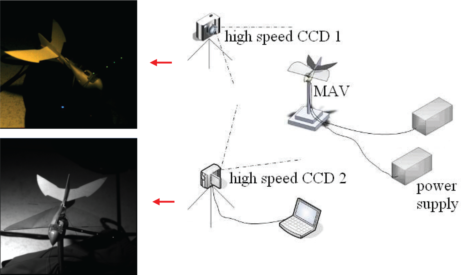
The experimental setup of the trajectory capture of the wing beating with two high-speed CCDs from different view directions (the left two pictures showing the corresponding two images of the MAV by Troubleshooting HR and Phantom V4.2, respectively.)
For equalizing the image dimensions of these two high-speed stereo vision cameras, a scaling rule of 15×15×15cm3 with 23 fluorescent points of known coordinates for calibration should be made in advance and is shown in Fig. 5. We put the scaling rule at the same location as the MAV and took two images of the scaling rule using the two high speed cameras, as in Figs. 5 (a) and (b). The rule of thumb for choosing a proper view angle is that all the 23 points of the scaling rule should be clearly “seen” by the two high speed cameras under this view angle arrangement. The embedded KwonCC software in the Kwon-3D system with its image measurement capabilities yielded an acceptable reconstruction error of 0.14mm, which is shown in Fig. 5(c).
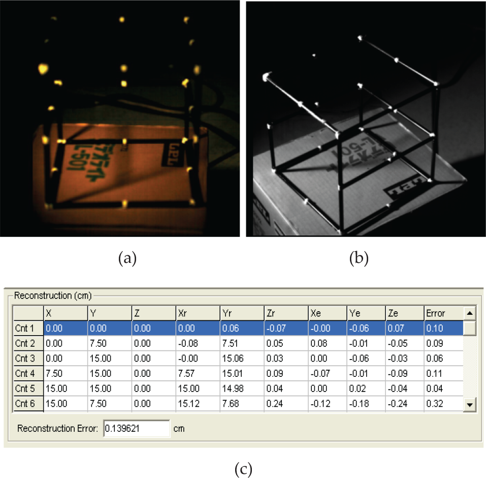
The scaling rule, of 15×15×15cm3, with 23 pre-known coordinates for dimension calibration and error evaluation: (a) the image taken by Troubleshooting HR; (b) the image taken by Phantom V4.2; (c) the table for evaluating the reconstruction error (only six of the 23 known points are shown with 3D coordinates here.)
These two high-speed cameras with precise coordinates finally take their respective images of the MAV with orthogonal view directions. These cameras record following image post processing and the 3D coordinate calculation of the nine LEDs on the wingskin in the next sub-section. For the purpose of auto-capturing the nine LED points, all the background light sources are shut down during the high speed photography procedure.
2.4 Post Processing of Wingtip Trajectory
Since the LED die is miniscule relative to the already small size and light weight of our MAV, the LEDs on the flapping wing served to enhance the light intensity for the visual motion sensing in this research paper. After the coordinate transformation was carried out by Kwon-3D, all the 3D coordinates of the nine LEDs on the aerofoil of the main wings are exported in *.txt format. We used LabVIEW-8.5‘s “front-panel” interface to receive the coordinate data from Kwon-3D.
Fig. 6 (a) and (b) show the basic gestures of the “Golden Snitch” under monitoring and the assigned positions of the nine LEDs. Fig. 6 (c) and (d) demonstrate the low-frequency wing beating of 3Hz flapping subject to 0.3V driving voltage. This operating motion matches the moving path of the original simple flapping mechanism design. The 3D trajectory of the simple flapping is without doubt a banana-shaped or C-shaped contour on a spherical surface with the pivoting point at the wing root [5]. However, when we increase the driving voltage to 3.7V, as well as increasing its wing beat frequency to 15Hz, a vibration parallel to the free stream direction and orthogonal to the original plunging direction is induced by the fluid-structural interaction [33]. This induced vibration adds to the original up-and-down plunging and constructs an oblique “figure of eight” trajectory of wing beating images. This overall wing beating “figure of eight” trajectory is confirmed by Fig. 6(e) and (f).

The “front-panels” of LabVIEW-8.5 showing the 3D trajectories of the nine-LED indicator representing the real flapping motion of the “Golden Snitch”: (a) Front view; (a) Front view; (b) Side view; (c) A simple flapping at driving voltage of 0.3V; (d) The projection of the nine-LED indicator from the side-view direction of a simple flapping at driving voltage of 0.3V; (e) Figure of eight flapping at driving voltage of 3.7V; (f) The projection of figure of eight flapping from the side-view direction at driving voltage of 3.7V.
The physical meaning of the oblique “figure of eight” trajectory herein has been investigated [33] and is different to the conventional horizontal “figure of eight” trajectory of hummingbirds and flies. The main contribution of the horizontal “figure of eight” trajectory is on the lift generation and it is good for hovering. However the oblique “figure of eight” trajectory of the “Golden Snitch” appears to have a greater influence on the thrust generation and is good for forward flight.
3. Results, discussion and new application
One of various contributions made by this paper is to apply a stereo-vision system to detect the absolute positions of the LEDs installed in the main wings. As stated in the introduction, a visual motion sensing technique is usually applied to detect the motion of the whole body, but is seldom used to detect the motion of part of the body. With the calibration of the stereo vision system, not only have the flapping trajectory of the discrete LED points on the wing aerofoil been plotted, but also the time-varying viewgraph of the aerofoil of the main wings' deformation situation is plotted for each time step from the output data in relation to the flapping trajectory. Moreover, a cubic scaling rule of 15×15×15cm3, with 23 pre-known coordinates for dimension, is designed to compensate for the reconstruction error in Fig. 5(c) before the designated experiments were performed.
We used Matlab software to transform at least 71 sets of the measured 3D coordinates in Fig. 6 into 71 interpolated profiles. Each interpolated wing profile is constructed by the 3D coordinates including the nine LED points and two fixed points on the centreline of the wing frame corresponding to a certain moment of the wing beating cycle. Herein we define 0° (or 360°) as the very beginning of the down stroke half cycle and 180° as the onset of the upstroke half cycle. We therefore selected phase angle profiles every 60° and assembled them together in Fig. 7 and 8. Fig. 7 denotes the low driving voltage case of 0.3V and Fig. 8 denotes the high driving voltage case of 3.7V. These continuous figures show the moments of the down stroke half cycle (60°→120°→180°), which are proceeded by the upstroke half cycle (240°→300°→360°=0°).

The deforming profiles of the flapping membrane wing corresponding to different phase angles of a wing beating cycle; driving voltage=0.3V; (a)60°; (b)120°; (c)180°; (d)240°; (e)300°; (f)360°.

The deforming profiles of the flapping membrane wing corresponding to every 60° phase angle of a wing beating cycle; driving voltage=3.7V; (a)60°; (b)120°; (c)180°; (d)240°; (e)300°; (f)360°.
Three aspects of observation can be revealed from Fig. 7 and 8 as follows:
From Fig. 7, which shows the low-frequency flapping, all the wing profiles show a concave, upwards (∪) shape or a negative camber aerofoil due to the dominant self weight of the wing skin. Whereas, the high-frequency flapping case of the down stroke period in Fig. 8 shows some moments with a concave, downward (∩) shape or a positive camber aerofoil, due to the sufficient downward flapping acceleration. The concave upward or downward deformation of the flexible wing skin promptly responds to the instantaneous pressure loading from the unsteady flow fields. This observation matches our physical intuition and the high-speed images of a flexible flapping wing in Fig. 9 [21, 33–34].
From the profile shape of the 0° or 360°-phase angle profile with the highest wingtip position or the top dead point (Fig. 8), we can observe the stroke reversal phenomena, i.e., the transition from the upstroke flapping to the down stroke flapping. Herein, the rear portion of the wing profile from the strengthened rib to the centreline turns to concave down (∩) from concave up (∪) during this stroke reversal. The shape of the 180°-phase angle profile also exhibits the other stroke reversal, which is the transition from down stroke flapping to upstroke flapping.
In Fig. 8, the wing portion from the leading edge to the strengthened rib seems to be almost flat and is without substantial curvature. This contour is therefore not beneficial to the positive camber of the down stroke aerofoil and is weak in lift generation. As we have already stated in [27], the addition of the strengthened rib is used for the reinforcement of the global flexible wing. By using the parylene MEMS process, the parylene-encapsulated wing is substantially strengthened, which makes the rib structure unnecessary. Considering the lift enhancement of the flapper and the weight reduction for the MAV, we suggest removing the rib in the next generation design of the MAV.

Wing profiles of the “Golden Snitch”: taken by a high speed camera during its flapping [33].
3.1 New Application to CFD using Visual Techniques
The new application of the above 3D time-varying trajectory provides a model of the unsteady computational fluid dynamics (CFD) simulation around a flapping wing [35–36]. Due to the intrinsic difficulty of solving the fluid-structure interaction problem subjected to flapping, we would like to propose using this work's experimental 3D trajectory, which includes the aeroelastic interaction with the original up-and-down flapping at the same time. In other words, we focus solely on resolving the airflow field with time-varying wing boundaries.
For the purpose of clarity in our results, we will only take the example of 2D unsteady flapping flow. By intersecting the cross section along the quarter-span position (middle chord between wingtip and wing root) on the 3D deforming profiles of Fig. 7–8 via the SURFER software, the 2D wing profiles varied with time, corresponding to low and high frequencies of wing beating (Fig. 10). For the case of the driving 0.3V, all the aerofoils show negative camber; whereas for the case of 3.7V, some profiles during the down stroke half cycle show partially positive camber, which is good for lift generation.

The 2D aerofoil of the main wings geometries varied with time along the quarter-span cross section: (a) 0.3V; (b) 3.7V. The solid dots denote the leading edges during the down stroke, the hollow dots denotes the leading edges during the upstroke. The upstream wind is from the right hand side.
The next step is to input the 2D aerofoil contours across the quarter span position in Fig. 10 into a CFD code, e.g., FLUENT software for advanced flow field computation. Herein we only access the second order up-wind iteration scheme to obtain the steady state solution of the respective airflow field. This airflow field is subject to every aerofoil contour boundary and an ANSYS result of the quasi-steady state airflow problem was obtained accordingly. For every time step, the whole 2D airflow field domain with the deformable wing boundary was arranged in 80,000 square grids. The upstream velocity is set as 3m/s from the right hand side with the number of iterations set at 5,000. Fig. 11–12 show the equi-velocity contour of the flapping airflow field operated at 0.3V (3 Hz) and 3.7V (15 Hz), respectively.

Equi-velocity contour (unit: m/s) of the flapping flow field operated at 0.3V; wing beat frequency is 3Hz; free stream velocity is 3m/s.

Equi-velocity contour (unit: m/s) of the flapping flow field operated at 3.7V; wingbeat frequency is 15Hz; freestream velocity is 3m/s.
Even though the airflow fields in Fig. 11–12 cannot consistently generate inverted Karman vortex streets in the wake region [35], we can still gather meaningful results from the time-changing downwash flow and its unsteady lift information in the high frequency flapping case in Fig. 12. We compute the unsteady lift coefficients as the quasi-steady state CFD simulation in Fig. 13(a) by integrating the resultant force on the aerofoil of the main wings from Fig. 12 and then compare it to the previous experiment lift data of the “Golden Snitch” in Fig. 13(b) by using a wind-tunnel (where the wing beat frequency is 15.4Hz). From a qualitative aspect, these two sets of lift data of one-flapping cycle of high frequency cases have similar changing trends. Differing from most previous CFD research into flapping wings with a given rigid aerofoil or a sine-changing trajectory, this paper is believed to unveil one of the rare examples of a real shape aerofoil for the main wing or an artificial flapping MAV. Now, more advanced and accurate 3D CFD simulation and research is under way to verify the usefulness of the time-varying 3D trajectory data of the flexible flapping wing revealed in this paper.
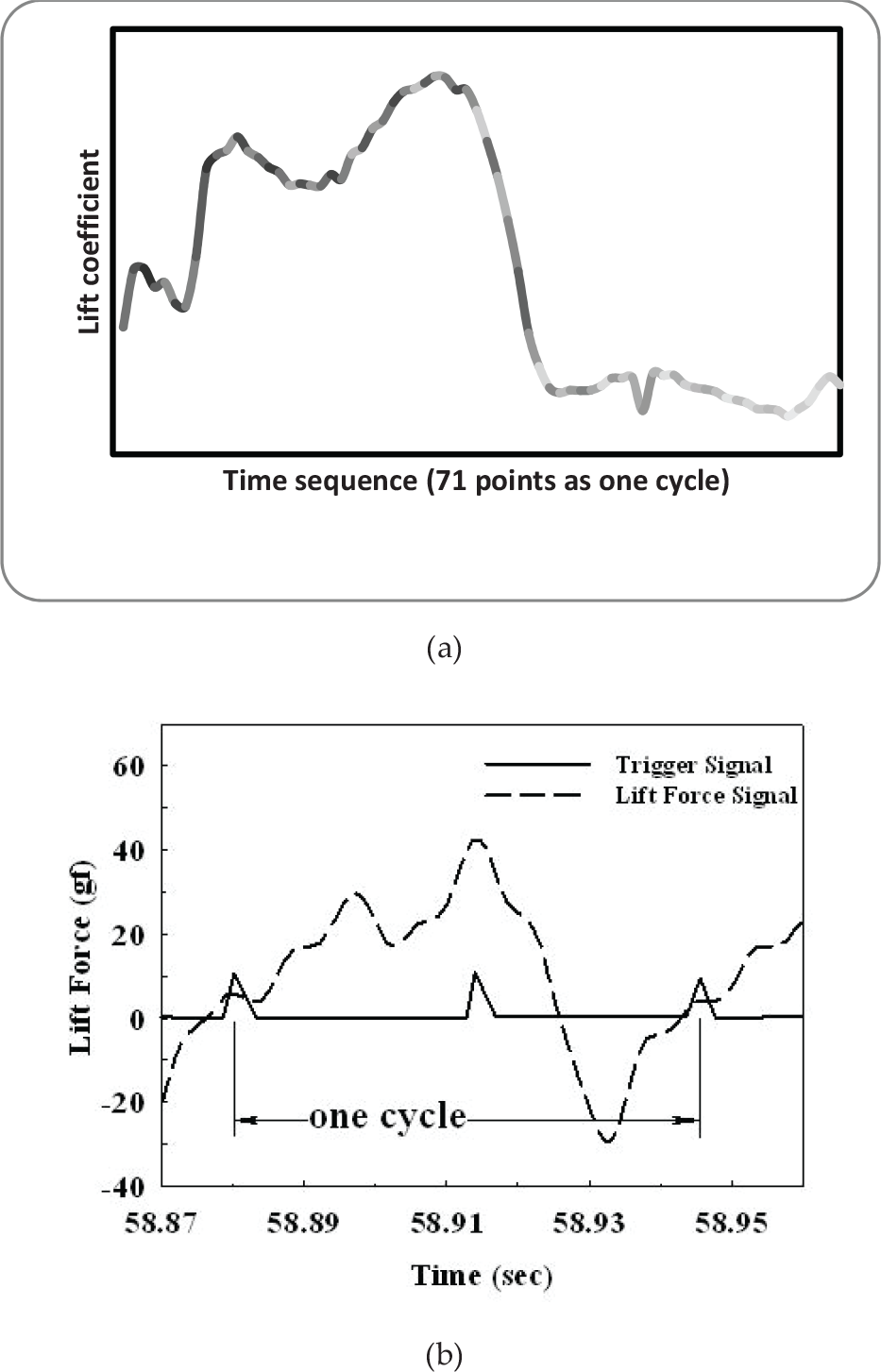
The unsteady lift force information: (a) the lift coefficient history of a flapping cycle predicted by this work; (b) the experimental lift data of the “Golden Snitch” in a wind tunnel [27].
4. Conclusion
A 3D trajectory detection framework for a bio-mimicking MAV “Golden Snitch” is initially constructed in this paper. A flexible wingskin embedded with a 9-LED array was fabricated and capsulated with a parylene protection layer. The obtained oblique “figure of eight” trajectory of the flapping MAV is confirmed experimentally. The detailed 3D coordinates, as well as 2D cross sections of the deforming wing profiles corresponding to different time steps, are also presented. The time-varying lift data of 15.4Hz flapping from our CFD results have the similar changing trends to the wind tunnel data. We believe that this paper may unveil one of the rare examples of a real shape aerofoil of the main wing or an artificial flapping MAV. From the 3D observation of the real wing trajectories herein, the modification of the flapping wing structure will lead to the possible emerging application of unsteady CFD simulation for flapping flyer research in the future.
Footnotes
5. Acknowledgements
We give our heartfelt thanks for the financial support of the National Science Council of Taiwan for the funding of project numbers NSC 98-2221-E-032-025-MY3 and NSC 101-2632-E-032-001-MY3. We also greatly value the technical expertise of Prof. Jr-Min Miao from National Pingtung University of Science and Technology, Prof. An-Bang Wang from National Taiwan University and Prof. Shung-Wen Kang from Tamkang University. In addition, Mr. Peter Te-Cheng Jang, with a B.S. in Mechanical Engineering from the University of California at Berkeley, is also highly appreciated for his technical writing amendments to this paper.