
Abstract
This paper presents the design of a novel radius-variable-gripper (RVG) for use as end-effector of high-voltage hot-line cleaning robot (HVCR). A eight-bar linkage mechanism is proposed to obtain the aim of 1-dof acutuation. According to the shape of insulators, the dimension design and kinematic analysis of RVG have been carried out. The optimization is performed to locate the joint points of arm segments, on which the brushes are mounted, approximately on the position circles in the whole opening-and-closing process of RVG. The prototype has been given finally, and it is showed that RVG is feasible to this special application.
1. Introduction
The contamination flashover of high voltage insulators is one of the severest threats to the safe operation of power systems. Especially in north of china, with the quick development of economy, the environment is somewhat polluted and destroyed, hence contaminaton flashover frequently happens when there is a mist. And the economic loss caused by the flashover of power system is huge. Cleaning high voltage insulators periodically is the only and effective way to greatly decrease the probability of contamination flashover. According to the IEEE standard(IEEE Std 957–1995, 1995), ‘the method used for insulator cleaning is dependent on the insulator material, construction, whether or not the line is energized, and on the type of contaminant to be removed’. In the past, because of the actual situation of china, the high voltage insulators were cleaned conventionally by hand wiping. Hand cleaning is thorough and effective, but is also a dangerous, tedious, time consuming, and expensive process that requires equipment outages. In 2001, Research Inst. of Robotics of Shanghai Jiaotong University started to study a teleoperated robot (Che, L. X.; Yang, R. Q. & Gu, Y., 2005), namely HVCR (High-voltage Hot-line Cleaning Robot), to clean the insulators in 220/330kV substations. Fig.1 shows the prototype of HVCR.
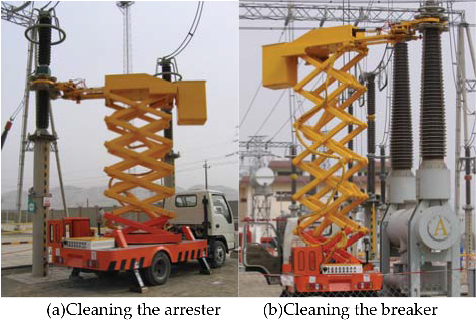
The prototype of HVCR
It should be noted that the term “insulator(s)” is used in a general sense to describe individual insulators and also the external insulating members of other apparatus. For example, in fig.1, the insulator cleaned in (a) is the member of a surge arrester, while in (b) is the member of a circuit breaker. With respect to the different high voltage devices, the insulators have distinct external shapes and dimensions, such as columniform(e.g. arrester in (a)) and coniform(e.g. breaker in (b)). The end-effector of HVCR is a kind of radius-invariable-gripper(RIVG), which can be used to clean the columniform insulator effectively. Similar grippers were presented in the past (Hirose, S. & Aoki, S., 1995)(Xu, W. C. & Yu, H. Y., 2000)(Gu, Y.; Yang, R. Q. & Song, T., 2006). During the applicaton, the RIVG showed two drawbacks. The first one is that it can not sweep the coniform insulator with radius-variable cross-section, such as circuit breaker. The second point, in order to clean the columniform insulators with different radius, the operator needs to change the end-effector frequently. These two disadvantages make the cleaning operation rather inconvenient and inefficient.
In the paper, a radius-variable-gripper (RVG), mimicking the motion of human fingers with one degree-of-freedom is presented. RVG is composed of two eight-bar linkage mechanisms, actuated by a single hydraulic cylinder. In the last few decades, a large number of anthropomorphic, prosthetic and non-prosthetic end effectors have been developed and reported, a detailed review of which is given in literature(Bicchi, A., 2000)(Okamura, A. M.; Smaby, N. & Cutkosky, M. R., 2000). Most of the researchers aim to design end-effectors which offer considerable flexibility, particularly in the range of objects that can be handled, both in shape and mass. Bekey(Bekey, G. A.; Tomovic, R. & Zeljkovic, I., 1990) studied a five-fingered end-effector with four degree of freedom, named Belgrade/USC hand. Miodrag (Miodrag, R., 1989) developed a mechanical hand possessing a feature he called self-adaptability. Crowder(Crowder, R. M. et al., 1999) designed a multi-fingered end-effector for unstructured environments, which located the finger actuators within the base and used mechanical linkages to transfer motion. Unlike the previous designs, in this research, the gripper RVG is a kind of special perpose manipulator used in relative structured environment. It can be used to clean not only the columniform insulator, but also coniform ones. The operator can adjust the radius of the gripper conveniently rather than changing the manipulator to clean different columniform insulators. Furthermore, the radius of RVG can be regulated continually when cleaning the coniform insulator from top to bottom(see (b) of fig.1). In the following sections, the details of the design process of RVG will be described.
2. Operating principle of RVG
The RVG has been designed for simple drive and easy control rather than to increase its dexterity and flexibility. The design of RVG is based on the finger configurations of human hands. Fig.2 illustrates the two different working states of RVG. In fig.2, (a) and (c) show that RVG is cleaning the top and bottom part of a coniform insulator, respectively; (b) and (d) show the pose of RVG when it cleans the different parts of a coniform insulator. The gripper is composed of two arms. Each arm includes four segments in series. Motions of the arm segments are not individually controllable, but they are connected by linkages. And, an insulating hydraulic cylinder(Che, L. X.; Yang, R. Q. & Gu, Y., 2006) is used to drive the linkages, which results in motions approximating a human hand. Inside the arm segments, series of gears are installed to transmit the power from the hydraulic motor to brushes.

The working states of RVG
3. Analysis of the mechanism
3.1. Mechanism description of RVG
There has been much research on the creation of a robotic end-effector that is similar, in function and appearance, to the human hand. Among these researches, the mechanisms with one degree-of-freedom include six-bar linkages, gears connected in series and cable mechanism (Light, C. M. & Chappell, P. H., 2000)(Nechev, D.; Cleghorn, W. L. & Naumann, S., 2001)(Guo, G. & Zhang, L., 1993). At LARM in Cassino, in order to obtain one degree of freedom actuation for an anthropomorphic finger, a study of the operation of an index human finger has been made(Figliolini, G. & Ceccarelli, M., 2002), and the design of driving mechanisms for fingers has been carried out(Rodriguez, N. E. N.; Carbone, G & Ceccarelli, M., 2006). Considering the insulation property and lightweight requirements, in this study, the gripper adopts an eight-bar linkage mechanism.
Fig.3 shows this eight-bar linkage mechanism used in one arm of RVG(To be simple, the other symmetrical arm is not showed in fig.3). In fig.3, the arm is composed of three crossed four-links OABC, CDEF and FGIH connected in series and the distal segment IHJ. The main goal here is to determine the position of some key joint points, on which the brushes are mounted, rather than to only study the motion locus and contact force of fingertip J. In order to clean the coniform insulator, in the process of opening-and-closing of RVG, joint points O, C, F, H, and J, on which the brushes are mounted, should be positioned on a series of approximate circles which is named positon circle. And, the centers of these position circles should be located on the symmetry axis of the two arms.

Schematic diagram of RVG
3.2. Analysis of joint position
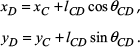
Using vector analysis approach(Guo, G. & Zhang, L., 1993), in Fig.3, the coordinate of point A and C can be calculated directly:

According to the coordinate of joints A(x
A
, y
A
) and C (x
C
, y
C
), the coordinates of point B are:

Where,
And the coordinates of point D are:
Where,
Similarly, the coordinates of E, F, G, H, I and J can be calculated.
3.3. Location error of joint F H J
The location error e
i
of points F, H and J is defined as the difference between the length of FOc, HOc and JOc and the radius of position circle respectively:

Where, as shown in Fig.4, b and y c are the coordinates of the center Oc of a position circle; R is the radius of the position circle.
The location of position circle
As shown in Fig.4, the vertical coordinate of center O
c
and the radius of the position circle are:

Where, l1 is the length of link l OC .
4. Analysis of operational ability of RVG
For the insulators to be held and cleaned, the minimal and maimal cleaning radius of RVG should be determined according to the exact dimension of these insulators.
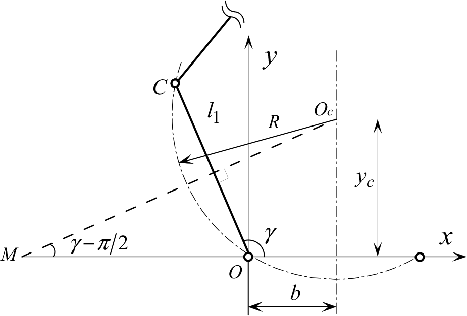
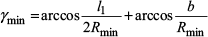
4.1. Minimal cleaning radius of RVG
As shown in Fig.5, when the distance between the end point J of one arm and the root point O' of another arm equals to S, the radius of the position circle circumscribed by polygon OCFHJ is the minimal cleaning radius, denoted by Rmin. S is the minimal distance determined empirically to avoid the collision between two arms of RVG. Therefore:
Minimal cleaning radius
4.2. Maximal cleaning radius of RVG
Fig.6 shows the maximal cleaning radius of RVG, when it is cleaning the bottom part of the insulator with the biggest radius. Therefore:
Maximal cleaning radius


Where, Rmax is denoted to the maximal cleaning radius of RVG.
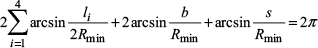
4.3. Maximal expanding radius
When the robot does not work, RVG expands fully. Fig.7 shows the state of maximal expansion of RVG with a single arm. As shown in Fig. 7, line JOc is perpendicular to the symmetry axis of RVG. Therefore:
Maximal expanding radius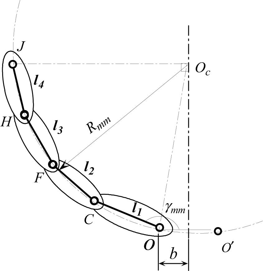


Where, R mm is the radius of the position circle in the state of maximal expansion of RVG
5. Optimization of RVG
To the design of an anthropomorphic finger, usually, four optimality criterias must be fulfilled basically(Rodriguez, N. E. N.; Carbone, G & Ceccarelli, M., 2006):
Human-like motion and grap;
Compact size;
Actuation lightweight and efficiency;
Position and force control.
However, the design of RVG in the paper is to attach the problem of a finger-like mechanism for a very specific application. The kinematics of the motion is the most important requirement for RVG. Specifically, the aim of the optimal design is to locate the joint points O, C, F, H and J approximately on the position circles in the whole opening-and-closing process of RVG. In the following sections, the design variables are determined, an objective function is selected and the design constraints are formulated.
5.1. Design variables (DV)
Variables uesd to determine the dimensions of points C,F,H and J include: b, α, l1, l2, l3, l4, φ1, l CD , θ1, l CF , l GF , l ED , φ2, l EF , l FH , θ2, l GI , l HI , θ3, l HJ . Considering the rationality of mechanism design and the simplification of manufacture, links l1, l2, l3 and l4 have the same length, that is l1 = l2 = l3 = l4 = l, and b = l/2. Therefore, 16 design variables have been selected finally, denoted by a vector X = [x1, x2, x3,,, x16].
5.2. Objective function
In order to keep points O, C, F, H and J on the same position circle, the location error e
i
of these points should be as small as possible. For the sake of clarity, the expression of e
i
is rewritten here as:

In addition, both e
H
and e
J
should keep positive, when the state of RVG varies from maximal cleaning to maximal expanding. Therefore the optimal function can be:
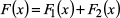
Where,

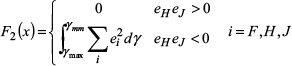
F1(x) represents the squared sum of e i of point F, H and J from the state of minimal cleaning to maximal cleaning.
In equations (8)and(9), γmin, γmax and γ mm are obtained from equations (2), (4) and (6) respectively.
5.3. Constraint condition
According to the actual size of insulators, Rmin = 275mm and Rmax = 400mm. Substituting Rmin and Rmax into equations (1)and(3), then the value of l varies between 247.2 and 297.4, and the value of each of the other variables varies between its two limits, as shown in Table 1:
Contraint conditions for Design variables

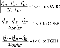
In addition, the constraint conditions for the three crossed four-bar linkages are respectively:
5.4. Results of optimization
The optimization of RVG is a single-objective nonlinear optimization problem in the form of min
Results of optimization

6. Discussion of the Optimal result
6.1. Reconfiguration of the eight-bar linkage
Using the optimal results showed in table 2 to reconfigurate all the components of the eight-bar linkage, then the optimal mechanism will operate as shown in the simulation of Fig.8.

Expanding movement of RVG after optimization
According to the definition of location error of joints E, H and J, expressed by

The location error of point E, H, J after optimization
However, the study in the paper is the primary sample in using the principle of human-like finger mechanism to the design of end-effector for HVCR. In the following research, the other design criterias, such as actuation lightweight and efficiency, should be further studied.
6.2. Compensation for the offset of the center of position circle
As shown in fig.4, in the process of expanding of RVG, the center O
c
moves up along the line x = b. The offset of center O
c
should be compensated with the help of another mechanism of HVCR to avoid the collision between the gripper and the insulator. As mentioned in previous sections, the vertical coordinate of O
c
is expressed by 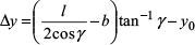
Where,
7. Mechanical design for the prototype
A prototype of RVG(see fig.10) has been built according to the reconfiguration shown in fig.8. In fig.10, (a)∼(e) show the different working states of RVG.
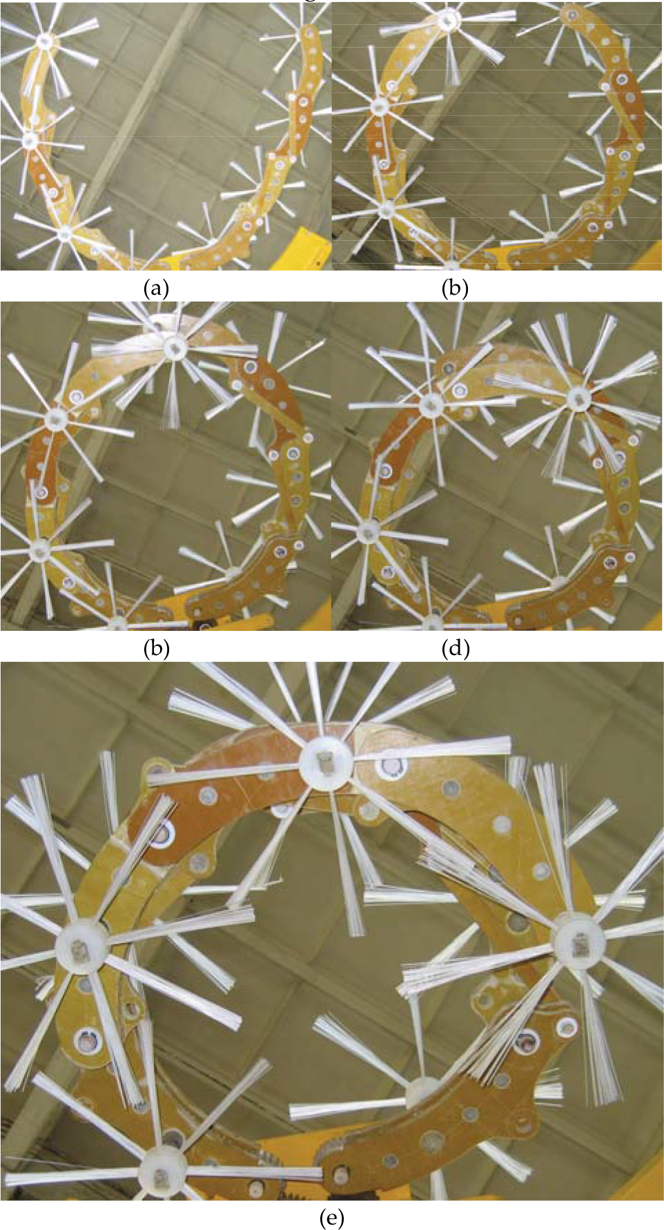
The different states of prototype of RVG
Considering the property of high-voltage insulation, all elements of RVG are manufactured by insulating material, see fig.11, all links and segments of arms are made in FRP (Fiberglass-Reinforced Plastics). In addition, the insulating journal bearings (made in Polytetrafluoroethylene) are used for the support of gear transmission and relative rotation of segments. In fig.11–b, in order to avoid the interference of links and brushes, the different segments have been assembled on different level.
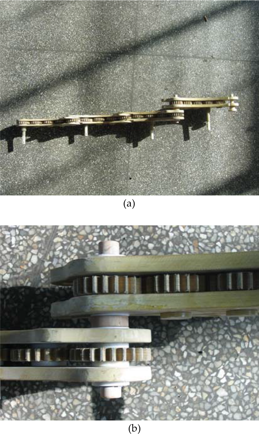
Parts of RVG
8. Conclusion
In the paper, an eight-bar linkage with one degree of freedom is proposed for use in the design of the radius-variable-gripper to clean the insulators in high voltage substation. The joint points on the RVG, on which the brushes are assembled, are located on a series of position circles approximately during the whole process of opening-and-closing. The RVG is able to clean both columniform and coniform insulators in substations.
This research is a primary example of how such finger-like mechanism can be brought also in other very specific fields of engineering application. And much more studies including deeper kinematic analysis and velocity mapping, should be done to optimize this gripper in the following works.