
Abstract
Skid-steered mobile robots have been widely used in exploring unknown environments and in military applications. In this paper, the tuning fuzzy Vector Field Orientation (FVFO) feedback control method is proposed for a four track wheel skid-steered mobile robot (4-TW SSMR) using flexible fuzzy logic control (FLC). The extended Kalman filter is utilized to estimate the positions, velocities and orientation angles, which are used for feedback control signals in the FVFO method, based on the AHRS kinematic motion model and velocity constraints. In addition, in light of the wheel slip and the braking ability of the robot, we propose a new method for estimating online wheel slip parameters based on a discrete Kalman filter to compensate for the velocity constraints. As demonstrated by our experimental results, the advantages of the combination of the proposed FVFO and wheel slip estimation methods overcome the limitations of the others in the trajectory tracking control problem for a 4-TW SSMR.
Keywords
1. Introduction
In recent years, many mobile robotic system applications have been developed. Several types of system have been designed and manufactured based on the locomotion systems of robots. With a 4-TW SSMR, there is no steering mechanism and the direction of motion is changed by turning the left and the right side tracked wheels at different velocities. Because of complex wheel-ground interactions and kinematic constraints, the path tracking control of the mobile robot makes it difficult to obtain an accurate experimental result.
In the literature, there are several approaches to solving the path tracking problems of a mobile robot. For example, a combination of kinematic and torque control frameworks using a backstepping technique to join robot kinematics into dynamics allows us to apply approaches from a model-dependent computed torque method (CTM) to a robust sliding mode control (SMC) method [1]. In [2], the adaptive SMC is designed for an uncertain dynamic model with parametric uncertainties associated with the camera system. Another type of controller for an autonomous mobile robot is the stable tracking control method which is proposed based on an error model of the kinematic model [3]. Although there are many interesting features to all these control methods, they are difficult to tune, in contrast to the flexibility of the fuzzy logic control (FLC). The fuzzy logic controller for the path tracking of a wheeled mobile robot is presented in [4]. A fuzzy adaptive tracking control method for wheeled mobile robots is proposed, where unknown slippage occurs and violates the nonholonomic constraint in the form of state-dependent kinematic and dynamic disturbances [5]. In [6], a pseudo-static friction model is used to capture the interaction between the wheels and the ground, and an adaptive control algorithm is designed to simultaneously estimate the wheel/ground contact friction information and control the mobile robot's trajectory as desired.
In previous work, the novel Vector Field Orientation (VFO) feedback control method was developed for a Differentially Driven Vehicle (DDV), a Threecycle Mobile Robot and a 4-WD SSMR in [7–9]. Also in [10], the extended VFO control method for a mobile vehicle was proposed to compensate for skid-slip phenomena.
In a mobile robot's field of operation, wheel slip limits traction and braking ability, especially for a four track-wheel differentially skid-steered mobile robot (4-TWD SSMR). Accurate estimation of slip is essential to obtaining the precise position of a mobile robot operating in unstructured terrain. Several approaches to slip estimation have been developed. For example, using a sliding mode observer (SMO) as a means to estimate slip parameters based on the kinematic model of a skid-steering vehicle is proposed in [11]. In another study, a novel method combining an optical flow algorithm with a sliding mode observer to estimate the slip parameters of a SSMR is introduced [12]. However, in order to validate the proposed method, it needs to be tested on more complex trajectories and longer travelling distances. Reference [13] proposes an experimental slip model for exact kinematic modelling and the parameters of this model are determined based on experimental analysis.
The contribution of this paper is the combination of the proposed FVFO and novel wheel slip compensation methods for the trajectory tracking of a mobile robot. First, the tuning fuzzy Vector Field Orientation (FVFO) feedback control method is proposed for a 4-TW SSMR. While the stable tracking control in [3] and conventional VFO feedback control methods in [7–10] do not perform well over a wide range of operating conditions because of the fixed gains used, the FVFO used the FLC to tune parameters of the VFO method. That is the flexibility of the proposed method, thanks to which we are able to obtain more precise trajectories. Second, in the field of mobile robotics, wheel slip limits the traction and braking ability of the robot; the methods in [11–13] retain these limitations when the robot is travelling on different ground surfaces with different and longer trajectory shapes. In this paper, we propose a novel method for online wheel slip estimation based on a discrete Kalman filter to compensate for the velocity constraints. The experimental results show that the combination of the proposed FVFO and novel wheel slip compensation methods overcomes the limitations of the others in the trajectory tracking control problem. This system can be enhanced by using trajectory tracking control for a 4-TW SSMR. The experiment is performed on the NT – Hazard Escape – 1®, as shown in Figure 1.

The NT – Hazard escape – 1 Mobile Robot
This paper is organized as follows: Section 2 introduces the experimental NT – Hazard escape – 1 mobile robot setup. Section 3 proposes a tuning fuzzy Vector Field Orientation (FVFO) feedback control method for a mobile robot. The implemented extended Kalman filter and slip estimation are designed in Section 4. The experimental results, including analysis and evaluation, are discussed in Section 5. Finally, Section 6 presents the conclusion.
2. The experimental NT-Hazard escape – 1 mobile robot setup
The NT – Hazard escape – 1 mobile robot, with four NT – track wheels, considered in this study, has been applied in a disaster area, has been used to run through and observe rough terrain including a construction site and has run up stairways. A robot with small actuators was created for the first time in Korea, providing the robots with various functions. Each of the eight motors operates and functions independently. The robot can easily lift 2 tracks even when fully loaded. The robot can move whilst maintaining its central balance like a tank. In addition, the RS232C is supported and enabled by an embedded board and computer which operate through wireless telecommunication. The dimensions of the mobile robot are shown in Figure 2.
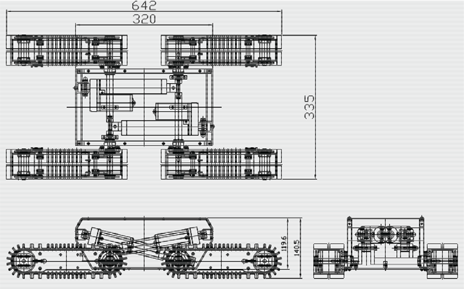
Dimensions of the NT – Hazard escape – 1
For research purposes, an experimental mobile robot was designed. The system configuration is represented by the element component configuration shown in Figure 3, while a real photograph of the experimental system is displayed in Figure 4. Using these figures, the AHRS (AHRS – 03 – 300) was mounted on the top centre of the robot on a base platform. The AHRS specifications are shown in Table 1. Two incremental encoders (E40H-8-1024-3-N-5) were installed on the robot's front left and front right track wheels. A notebook model ASUS U36S was used to collect data from the sensors through an AVR 128-pro board and also performed all the algorithms in real-time. Here, the software control algorithm for the system was coded in the programming language C# (using the Microsoft Visual Studio 2008 version).
The AHRS – 03 – 300 specifications

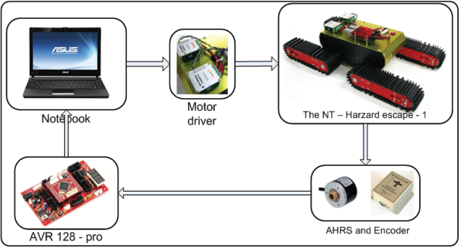
The system configuration

The real photograph of the experimental system
During the experiment, the measurement sampling frequency for the AHRS and incremental encoders was set to 20Hz. The robot was programmed to follow desired trajectories on concrete terrain. Based on the measurements from these two sensors, the robot position values are derived using a Kalman Filtering technique and then the trajectory tracking controllers are applied to drive the robot along desired trajectories.
3. The tuning Fuzzy VFO feedback control method for the path tracking of the mobile robot
A path tracking control method is used to control the trajectory of the experimental robot's motion as desired, based on closed–loop control systems and the sensor fusion technique for feedback control signals.
Figure 5 shows a diagram of the implemented control algorithm. As shown in this figure, the control systems include three closed-loop controls: two low-level closed-loop controls for motor speed on the left and right sides, and a high-level closed-loop control for the robot's position. For low-level closed-loop controls, discrete PID controllers are applied, and the tuning fuzzy VFO (FVFO) feedback control method is designed for high-level closed-loop control. Then, the extended Kalman filter (EKFx) is utilized to estimate the positions, velocities and orientation angles, which are used for feedback control signals in the high-level closed-loop control, based on the AHRS kinematic model and velocity constraints. Additionally, a discrete Kalman filter for the slip estimator (KFλ) is proposed to compensate for the velocity constraints for EKFx in order to improve the accuracy of estimation values. The EKFx and KFλ are implemented simultaneously using measurements from the AHRS sensor and encoders. They are introduced in the next sections.
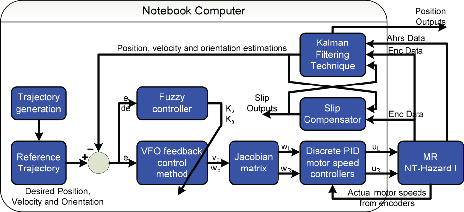
The diagram of the implemented control algorithm
3.1. The VFO feedback control method
The stable tracking control (STC) method is introduced in [3–4], based on an error model of the kinematic model. The linear velocity output v c and the angular velocity output ω c of the control law are:

where
or

where
In the VFO strategy the trajectory tracking control problem is divided into two subtasks: convergence of position and orientation to the desired values. The vehicle is driven by the pushing controlv
B
with a careful pushing strategy, while the orienting controlw is responsible for matching the vehicle's heading vector with the position convergence vector. Such tasks are accomplished with the help of the choice of a proper convergence vector field, which defines the instantaneous convergence direction and orientation of the vehicle. The control position errors
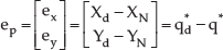
where

where
Using kinematics modelling (2), the simultaneous attenuation of both the position and orientation errors during a transient stage requires highly oscillatory vehicle movement, which usually does not occur in practice [10]. To avoid transient oscillations the third component of h can be designed to introduce the so-called auxiliary orienting variable

where

Since the third component, which is the convergence orientation, is:

where

Using the principles of the VFO method, the VFO feedback control law is:


where v
c
and ω
c
are the linear and angular velocity outputs from the VFO controller. The left and right angular speed inputs

where r is the radius of the tracked wheel and L is the distance between the left and right sides of the robot.
3.2. The tuning fuzzy VFO feedback control method
From Equations (5) and (8), it can be seen that the position and orienting components of the convergence vector field are similar to a PD control, but the derivative parameter is fixed at one. The

where the

The tuning fuzzy VFO scheme of the high-level closed-loop control
From Figure 6 it can be seen that there are three fuzzy tuners for the three output parameters

Membership functions of inputs |e x |, |e y |and |e a |
Membership functions of inputs |de x |, |de y |and |de a |
There are three outputs from the three fuzzy tuners: k
px
, k
py
and k
a
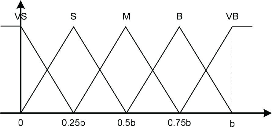
with the outputs having ranges from 0 to 1. Singleton membership functions are then used for the fuzzy output partitions. Figure 9 shows five membership functions (VS, S, M, B, VB) corresponding with the five output states (very small, small, medium, big, very big), respectively. Because the same properties of the three output parameters

Membership functions of the outputs kp x , kp y and kp a
Rule i: If |e x | (|e y |or |e a |) is A i and |de x | (|de y |or |de a |) is B i then k px (k py or k a ) is C i , i = 1, 2,…, n
where n is the number of fuzzy rules; A i , B i and C i are the i th fuzzy sets of the input and output variables used in the fuzzy rules. A i , B i and C i are also the linguistic variable values of the input and output signals in the fuzzy tuners.
The rules of the fuzzy tuners are designed as shown in Table 2. The MAX-PROD formula is chosen as the main strategy for the implication process:
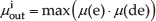
where

where

where
Rule table of the fuzzy tuners

4. Extended Kalman Filter (EKFx) and Slip estimation (KFλ) design
4.1. AHRS kinematic model and velocity constraints
4.1.1. AHRS kinematics model
We define a navigational reference frame N(X,Y,Z) and robot body frame B(x,y,z) as shown in Figure 10. Let PN(t)=[XN(t),YN(t),ZN(t)]T

An AHRS kinematics model of a 4TW SSMR
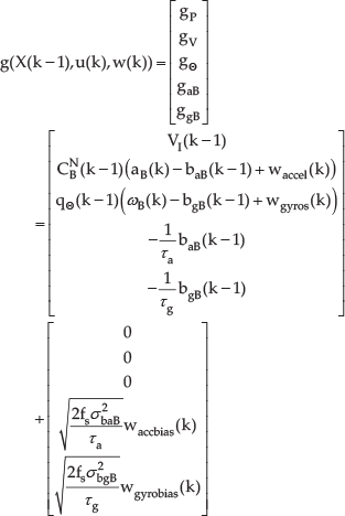
After subtracting the constant offset and local gravity vector, the acceleration and angular rate models can be described by [15]:

with


where the true acceleration vector, the true angular rate vector of the vehicle in the B frame, the acceleration white noise and the angular rate white noise are
We define the state vector

where


where
4.1.2. Velocity constraints
In the 4-TW SSMR, the motors that power the wheels on each side are geared internally to ensure that the velocity of the two adjacent wheels on each side are synchronized and thus have the same velocity at ground contact. We define

where

The 4-TW SSMR kinematics

where

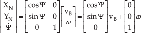
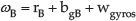
Because of the symmetric mechanical structure of the robot, it can be assumed that the centre of mass (COM) of the robot is located at the centre of the geometry (COG) of the body frame. The AHRS coordinate is located at the COG of the body frame in the B frame, as shown in Figure 10. Using two wheel encoders (one for each side of the vehicle), we obtain the AHRS velocity vector
Based on [16], since the four tracked wheels of our robot are always in contact with the ground and since the AHRS is fixed on the robot platform, the velocity constraints

The variances
4.2. Extended Kalman Filter (EKFx) design
Now, we define the state variable's vector

where the AHRS input signals at the k
th
sampling time are
and
With velocity constraints (27), the AHRS velocities in the B frame are considered as the measurement vector
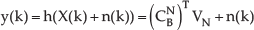
where n(k) represents measurement noises. We assume that the measurement noises n(k) are independent, zero-mean and Gaussian white noise, i.e., n(k)~N(0, R). The covariance matrix of the measurement noise is:

where
4.3. Slip estimation (KFλ) method
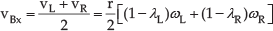
In order to determine wheel slip parameters to compensate for the velocity constraints and their variance values in Section 4.1.2, a discrete Kalman filter, denoted by KFλ, is designed. By giving v
Bx
in the body frame B and yaw rate

By substituting (33) into (25), we have:


We define the unknown parameters:

Substituting (36) into (35), the relationship between the angular speed from the encoders and unknown parameters is described as:

The slip estimation based on the discrete Kalman filer (KFλ) is now established. We assume that the slip process is a random process and then the unknown parameter process can be modelled in discrete-time form

where

From Equation (37), a measurement model can be written which relates to the encoder measurement noises as:
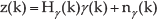
where

where


where

Based on previous descriptions, the estimated slip values

The dual estimation algorithm
The dual estimation equations

5. Experimental results
In this section, experiments were performed to prove the effectiveness of the combination of the proposed FVFO and slip compensation methods for the robot's position in a real-time application. The system was performed on concrete terrain in an outdoor environment. The experiments involve two scenarios:
Scenario 1: The mobile robot is controlled along a desired trajectory with two curves in two cases: without and with slip compensation.
Scenario 2: The mobile robot is controlled along a desired circular trajectory with a 2-m radius in two cases: without and with slip compensation.
5.1. The use of the FVFO method for mobile robot without slip compensation
In this section, the proposed FVFO method is performed in two scenarios without slip compensation. Additionally, the stable tracking control method (STC) and the conventional VFO feedback control were applied in order to compare them with the FVFO results.
In the first scenario, the output trajectories of the three methods are shown in Figure 13 are and compared to the desired trajectory. The response of STC is quite different from the desired response, while those of VFO and FVFO are close to the desired response. The linear and angular velocities of the three methods, shown in Figures 14 and 15, are also close to the desired velocities despite the mechanical vibrations and sensor noises.

The desired, STC, VFO and FVFO trajectories, respectively, without slip compensation in scenario 1

The desired, STC, VFO and FVFO linear velocities, respectively, without slip compensation in scenario 1

The desired, STC, VFO, FVFO angular velocities, respectively, without slip compensation in scenario 1
In Figure 16, the position error of FVFO, which is the distance from the estimated position of the robot at the defined instant to the nearest point of the desired trajectory, at any instance in time is the closest to zero compared to those of the STC and conventional VFO. The results suggest that the proposed FVFO has improved the performance of the solving of the path tracking problem. Consequently, the Root Mean Square Error (RMSE) of the robot's position of FVFO is the smallest (0.0494[m]), while those of the STC and VFO are 0.0994[m] and 0.0845[m], respectively.

The position errors of STC, VFO and FVFO, respectively, without slip compensation in scenario 1
The trajectory responses of the three methods in the second scenario are shown in Figure 17. The linear angular velocities and position errors of the three methods are shown in Figures 18, 19 and 20. It is clear that the FVFO result is the best (with the smallest RMSE (0.0688 [m])).
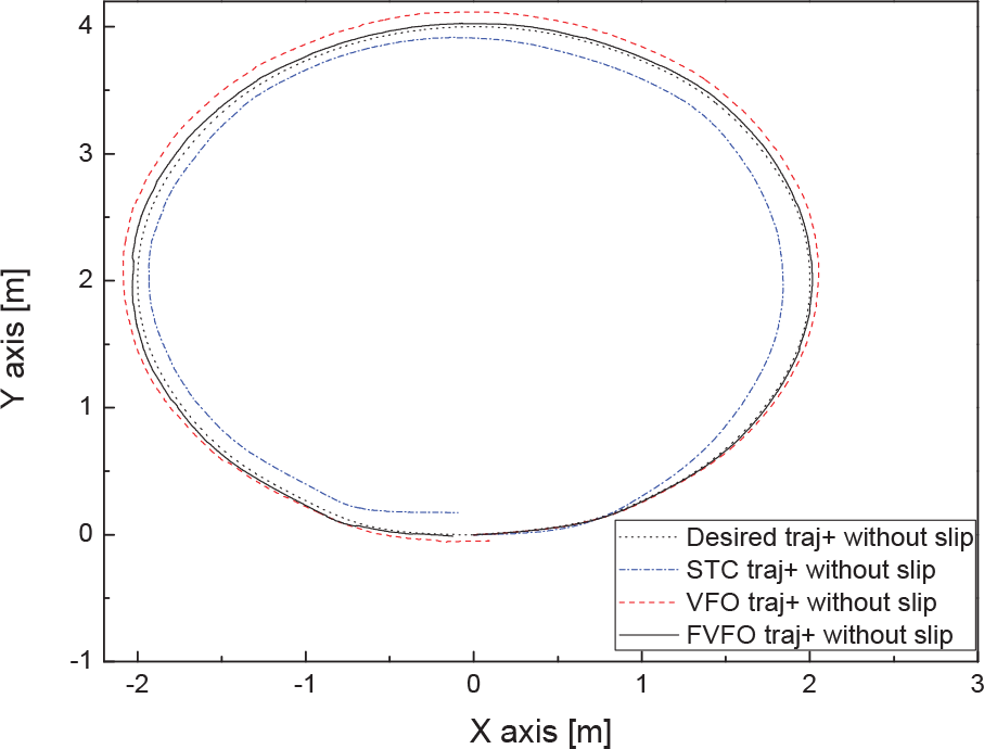
The desired, STC, VFO and FVFO trajectories, respectively, without slip compensation in scenario 2

The desired, STC, VFO and FVFO linear velocities, respectively, without slip compensation in scenario 2

The desired, STC, VFO, FVFO angular velocities, respectively, without slip compensation in scenario 1

The position errors of STC, VFO and FVFO, respectively, without slip compensation in scenario 2
5.2. The use of the FVFO method for a mobile robot with slip compensation
In Section 5.1, although the FVFO method reduced more position errors than the STC and VFO method, the system error is still significant. In the field of mobile robotics, wheel slippage limits the traction and braking ability of the robot, and causes large position errors in path tracking control. In this section, the system is performed again with slip compensation.
The STC, VFO and FVFO trajectories with slip compensation in both scenarios are shown in Figures 21 and 24. The FVFO responses with slip compensation are closest to the desired responses. Based on the slip estimation, the estimated values from EKFx are more precise than the previous values without slip compensation. By considering position errors, it is clear that the performance results with slip compensation are more accurate than previous results without slip, as shown in Figures 22 and 25. Consequently, the smallest RMSEs of the proposed method are 0.0124[m] and 0.0121[m] corresponding to the first and second scenarios.

The desired, STC, VFO and FVFO trajectories, respectively, with slip compensation in scenario 1
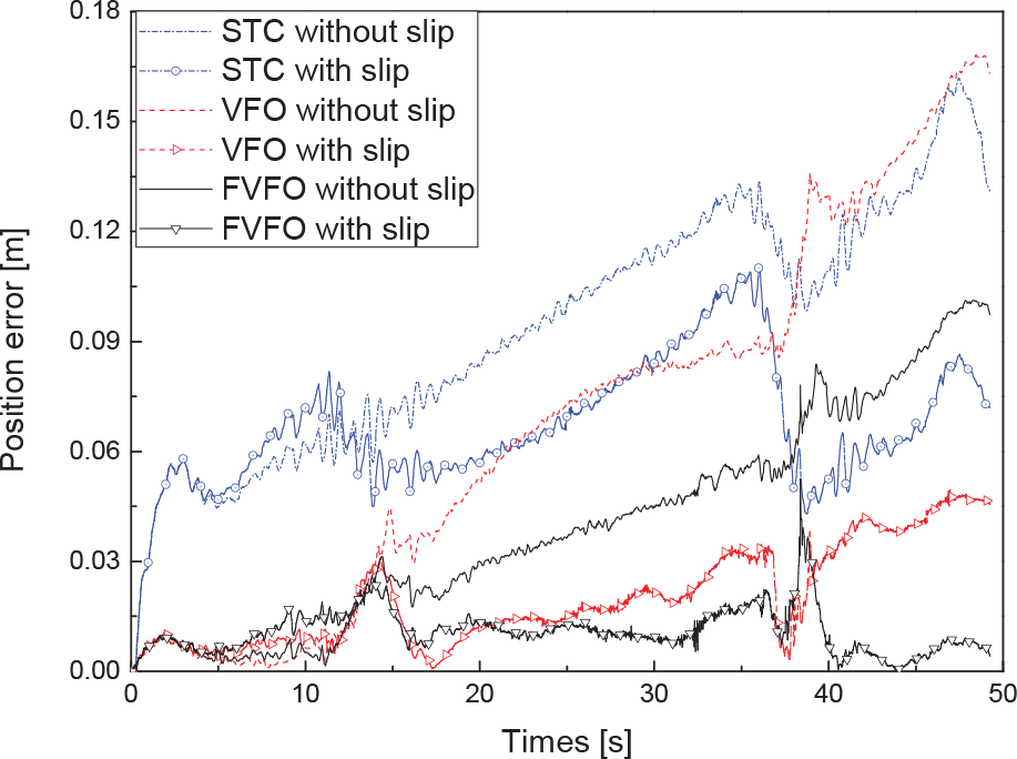
The position errors of STC, VFO and FVFO, respectively, without and with slip compensation in scenario 1
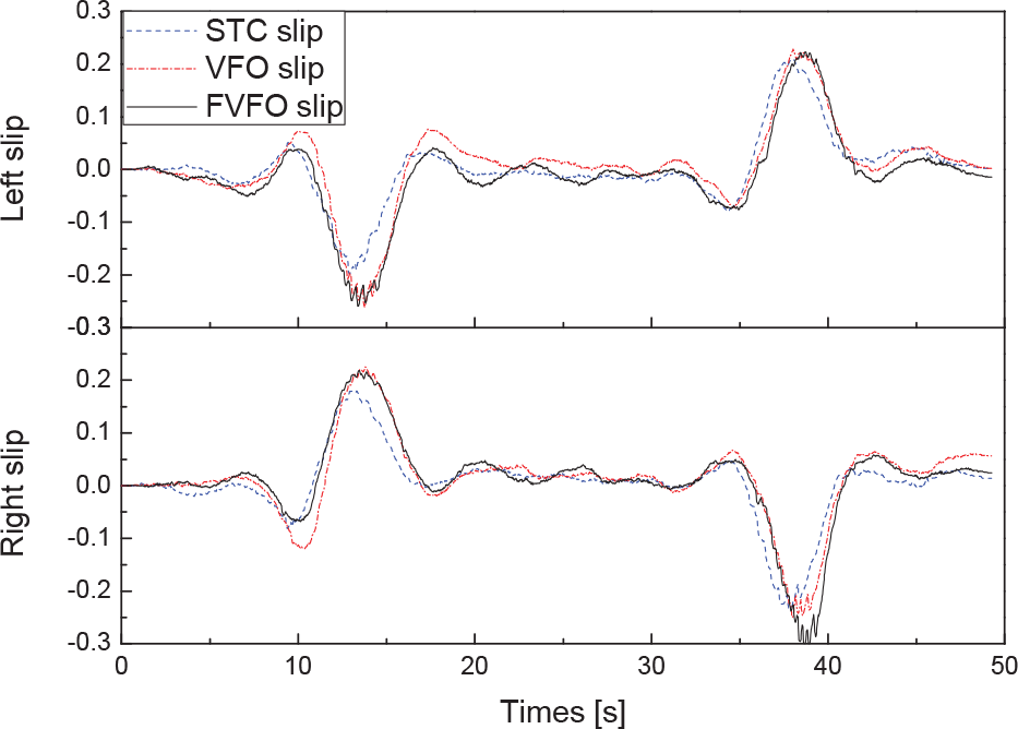
The estimated slip parameters of the left and right wheels of the STC, VFO and FVFO methods, respectively, in scenario 1

The desired, STC, VFO and FVFO trajectories, respectively, with slip compensation in scenario 2

The position errors of STC, VFO and FVFO, respectively, without and with slip compensation in scenario 2
It is clear from the above results that slip compensation is very effective in the field of mobile robotics. For the first scenario, the robot follows the desired trajectory, which has two curves. For the first curve, the angular speed of the right wheels is greater than that of the left wheels. Then, the traction phenomenon occurs on the right side while the braking phenomenon appears on the left. Consequently, the right wheel slip value is positive and the left wheel slip value is negative. Similarly, for the right rotation in the second curve, the right wheel slip value is negative and the left wheel slip value is positive. Furthermore, when the robot travels along the straight segment, less force is needed to drive the robot and the left and right wheel slips are close to zero. Figure 23 illustrates the estimated slip parameters of the left and right wheels for the three methods.
For the second scenario, the robot follows the desired circular trajectory counterclockwise. The angular speed of the right wheels is always larger than that of the left wheels. Consequently, the right wheel slip value is always positive and the left wheel slip value is always negative, as shown in Figure 26. All types of the estimated slip parameters in both scenarios are consistent. Tables 4 and 5 show RMSEs of all the experiments in this work.
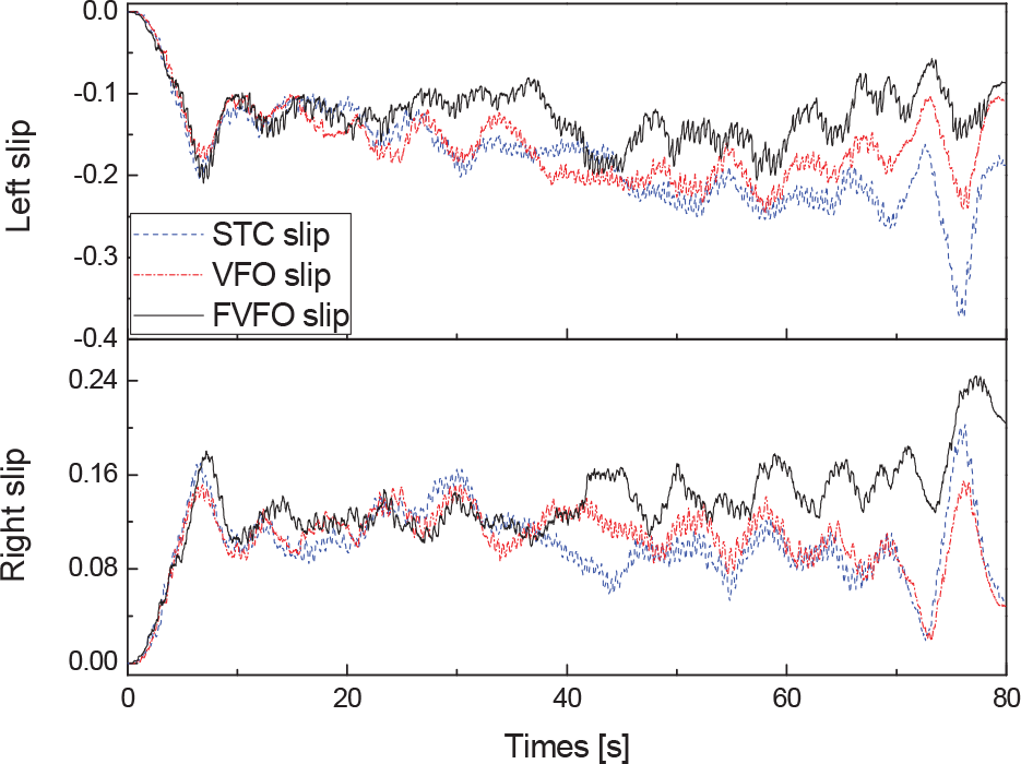
The estimated slip parameters of the left and right wheels of the STC, VFO and FVFO methods, respectively, in scenario 2
The Root Mean Square Errors (RMSEs) of the robot position in scenario 1

The Root Mean Square Errors (RMSEs) of the robot position in scenario 2

6. Conclusions
This paper presents experiments into a method of controlling the 4-TW SSMR along a desired trajectory based on estimated feedback control signals from an extended Kalman Filter, which uses measurements from an AHRS and two incremental encoders. In this paper, we proposed a combination of the proposed FVFO and novel wheel slip compensation methods for the trajectory tracking of a mobile robot. The extended Kalman filter is utilized to estimate the positions, velocities and orientation angles, which are used for feedback control signals in the FVFO method, based on an AHRS kinematic motion model and velocity constraints. Experimental results show the advantages of the combination of these two methods, which are effective at overcoming the limitations of the others in the trajectory tracking control problem for a 4-TW SSMR, e.g. the commercialized Hazard Escape I® mobile robot.
Footnotes
7. Acknowledgments
This work was supported by the 2011 Research Fund of University of Ulsan.