
Abstract
DDS is a recent specification aimed at providing high-performance publisher/subscriber middleware solutions. Despite being a very powerful flexible technology, it may prove complex to use, especially for the inexperienced. This work provides some guidelines for connecting software components that represent a new generation of automation devices (such as PLCs, IPCs and robots) using Data Distribution Service (DDS) as a virtual software bus. More specifically, it presents the design of a DDS-based component, the so-called Automation Component, and discusses how to map different traffic patterns using DDS entities exploiting the wealth of QoS management mechanisms provided by the DDS specification. A case study demonstrates the creation of factory automation applications out of software components that encapsulate independent stations.
1. Introduction
Today's factory automation applications are growing in size and complexity. In modern factory automation applications, industrial devices such as robots, Programmable Logic Controllers (PLCs) and Industrial PCs (IPCs) are changing from preprogrammed, stationary systems into machines capable of modifying their behaviour, based on interactions with the environment and other devices. Changes have also come about from users demanding higher efficiency, functionality and performance in the control of industrial plants [1]. Moreover, modern applications involve a large amount of information and an increasing number of industrial devices [2]. In this scenario, the integration of both horizontal and vertical communication is becoming a critical and complex issue [3]. Traditionally, factory automation communications have been organized in layers according to the so-called automation pyramid (Figure 1). This approach allows different types of technologies to be used in different layers of the automation pyramid. Historically, fieldbuses like Profibus or CAN were used at device and control levels, whereas typical office networks like Ethernet or Wi-Fi were preferred at plant level. Nowadays, these latter technologies, namely Switched Ethernet or Ethernet-modified architectures, are being increasingly used even at the bottom layers of the automation pyramid. This is due to several reasons [4]: (1) decentralization of applications is shifting intelligence to the distributed components; (2) vertical integration is gaining importance and (3) the adoption of IT standards is bringing about important cost reductions. Another driving force in factory automation results from the adoption of more powerful computing platforms by most industrial device vendors. These new platforms allow the introduction of modern software engineering techniques that improve performance and flexibility while, at the same time, reduce costs and time-to-market. However, modern factory automation applications require the integration of heterogeneous devices that execute different hardware platforms and Operating Systems (OS) [2].

Automation pyramid
In this context, middleware technologies provide high-level abstractions and interfaces to facilitate integration, reuse and development [5]. Some middleware specifications, such as CORBA [6, 7], ICE [8], OPC [9, 10], Web Services [11, 12] and DDS [13, 14] simplify the development of distributed factory automation applications. Even though middleware is typically organized in a hierarchy of several layers [15], most of the above cited specifications only address communication issues. Some authors have defined higher-level middleware architectures that provide new abstractions and services [16, 17] addressed to specific domains and applications.
In particular, the OMG Data Distribution Service (DDS) is an emerging middleware specification that follows the publisher / subscriber paradigm and implements a broad set of mechanisms to specify and manage Quality of Service (QoS) requirements in real-time applications. It has been used in several application domains such as avionics or defence. Although a few industrial automation systems have also been implemented with DDS, this standard has not yet gained much significance in factory automation applications. There are two main reasons for this fact: (1) It is a relatively new standard and (2) there is still a lack of development of environment support to facilitate enhancing de facto standard control systems like PLCs with DDS-based communication without deep programming knowledge [14]. In addition, although DDS is a very powerful technology it may prove complex to use for non-experienced users.
This paper fills the gap by providing some guidelines and abstractions to use DDS as a virtual software bus in the control layer for a new generation of factory automation devices (PLCs, IPCs and robots). More specifically, this work presents the generic architecture of a DDS-based component capable of providing QoS communication requirements in factory automation applications. Also, it identifies different types of traffic patterns among the controllers and maps them over DDS entities exploiting its wealth of mechanisms for QoS management.
The design of applications that use automation components allows concepts such as maintainability, reusability, flexibility and reconfigurability to be consolidated. For some time attempts have been made to integrate component architectures in industrial automation systems. One alternative is to use the IEC61499 standard [18] with component-oriented technologies. This standard proposes an open architecture for designing distributed automation applications capable of introducing modularity, reconfigurability and flexibility into distributed control systems. Vyatkin [19] defines the term IMC (Intelligent Mechatronic Component) for automation software design. This concept is close to the “Technological Module” introduced by Profinet-CBA [20]. Cengic et al. [21] introduce the term “automation component” over IEC61499, inspired by VHDL components. Black et al. [22] implemented IMCs as IEC61499 FBs (Function Blocks) within an approach to create multiagent systems that introduce autonomous and collaborative behaviour according to holonic principles.
The layout of the paper is as follows. Section 2 discusses several related works in the field. In particular, it analyses different middleware architectures used in robotics, as well as the most relevant kinds of traffic found in factory automation applications. Section 3 is the heart of the paper. It presents the design of a generic DDS-based component, the so called Automation Component and provides certain guidelines to map the different traffic patterns found in factory automation into DDS entities exploiting the richness of QoS management mechanisms provided by the DDS specification. Section 4 illustrates the use of this generic component in factory automation applications by means of a simple case study. Finally, Section 5 draws some conclusions.
2. Related work
This section describes some middleware architectures used in automation and robotic domains and discusses the major communication needs of factory automation applications.
2.1. Middleware for robotics and factory automation applications
Different architectural paradigms have been proposed to support the development of distributed and concurrent systems. In particular, object-oriented, component-based and service-oriented approaches are among the most relevant paradigms for the integration of software artefacts that require interprocess communication and event synchronization. Ref. [23] discusses its application to robotics. There have been several initiatives based on these paradigms to create frameworks and libraries for industrial robotic applications. Most of them are aimed at solving the following challenges [24]:
Simplify the development process
Ease integration
Support communications and interoperativity
Provide abstractions that hide heterogeneity and use the available resources efficiently
Offer frequently needed services
These frameworks have been analysed in [24, 25] and Orocos [26], Miro [27], Orca [28], Player/Stage [29], Aseba [30] and Robot Operating System (ROS) [31] are the most representative ones. Some of them are restricted to specific types of robotic applications such as mobile robots (e.g., Miro). One interesting initiative, Nerve [32], has developed a lightweight middleware aimed at networked social robotic applications. However, the robotics community still lacks well-accepted common software architectures, middleware and shared low-level functionality. In addition, since most of the previous initiatives have been developed within academic environments, the authors write software solutions that tend to be firmly based on their own architecture, middleware and robots [33]. Finally, these frameworks typically focus on solving the requirements of robotic applications only, without considering the integration of other industrial devices like PLCs or IPCs.
Previous initiatives have been built on top of different distribution middleware technologies. In particular, CORBA is used by Orocos and Miro, Orca is built on top of ICE, Nerve uses DDS, whereas the rest follow proprietary client/server communication approaches. Most of the previous frameworks barely implement the client/server paradigm. Only Orca, ROS and Nerve supply publish/subscribe one-to-many communications, which improve the overall performance of data exchanges and decouple discovery and communication tasks [34]. However, in most factory automation applications both client/server and publisher/subscriber paradigms should be combined.
Other authors propose alternative approaches for factory automation applications, such as using Service Oriented Architectures and Web Services [12, 35], but as shown in [36] these technologies may not provide an adequate performance in real-time applications like those usually found in factory automation.
It may be concluded from the previous discussion that simple approaches on top of more efficient technologies could be helpful in building factory automation applications with open industrial devices. When compared with previous approaches, the use of DDS as distribution middleware in the control layer of the automation pyramid provides several advantages. On the one hand it is a high performance middleware with low overhead, which is capable of supporting real-time communication on top of the TCP/IP stack. In addition, DDS is an open standard promoted by the OMG [13] that has been designed to work in different programming languages, on top of different computing platforms and operating systems providing a certain degree of independence. However, abstractions on top of DDS are needed in order to ease the creation of factory automation applications. This work, as well as [37], goes in this direction. More specifically, DDS is used directly as a communication backbone to connect software components based on concepts adopted from the IEC61499 standard [18].
2.2. Traffic types in factory automation applications
This subsection discusses the main communication needs in the control layer of the automation pyramid. This layer connects different types of process controllers (mainly IPCs, robots and PLCs). In factory automation applications, it is necessary to provide at least three different communication types, associated with different operations [4].
Each of the previous traffic types adapts best to a particular communication paradigm. Periodic and aperiodic data communications may be distributed more efficiently by using the Publisher/Subscriber paradigm, ensuring that certain QoS constraints are met. In such cases the same information is frequently sent to a set of recipients. However, the Client/Server paradigm is better suited for most non-time-critical operations, which may be synchronous (a Client makes a request to a Server, which provides a response) or asynchronous (a Client makes a request to a Server, which is processed without response).
In this paper DDS has been chosen as the communication backbone since it is a high-level, high-performance standardized middleware that follows the Publisher/Subscriber paradigm. In addition, it provides platform/programming language independence. As shown in [34, 38] the use of the Publisher/Subscriber paradigm is well suited for distributed real-time systems like those found in factory automation applications. Moreover, DDS is a unique middleware that provides a rich set of parameters to control QoS constraints, such as transport priorities, deadlines, reliability or liveliness, as described in next section. However, since some typical operations found in factory automation (both request/response and request/non-response) adapt best to the Client/Server paradigm they should be adequately mapped in terms of DDS with no interference from other more stringent operations.
3. Building factory automation applications with DDS
This section presents the main contribution of the paper, consisting of the internal design of a DDS-based Automation Component for building factory automation applications. It also describes the mapping of the different types of communication needs in this domain in terms of DDS entities and QoS parameters. The section starts with a short overview of the DDS fundamentals.
3.1. DDS Fundamentals
The Data Distribution Service for real-time Systems (DDS) [13] is an emerging specification released by the Object Management Group (OMG). It provides a high performance platform-independent middleware for Data Centric Publish/Subscribe many-to-many communications. There exist several implementations of DDS that allow different programming languages (mainly C, C++ and Java) and general purpose OSs, like Windows, Linux and some RTOS to be combined. Open source and community distributions of DDS products, such as OpenDDS [39] or OpenSplice [40] are available.
DDS defines a virtual Global Data Space (see Figure 2), which is accessible to all applications: Publishers produce/write data, which are consumed/read by subscribers. Publishers and subscribers are decoupled in time, space and synchronization. For example, late joiners may obtain data issued before their activation even if the application that produced it has already finished or crashed. This behaviour must be properly configured by tuning the QoS properties. Data are described in a platform independent way, inherited from the CORBA specification, the so-called IDL (Interface Definition Language).
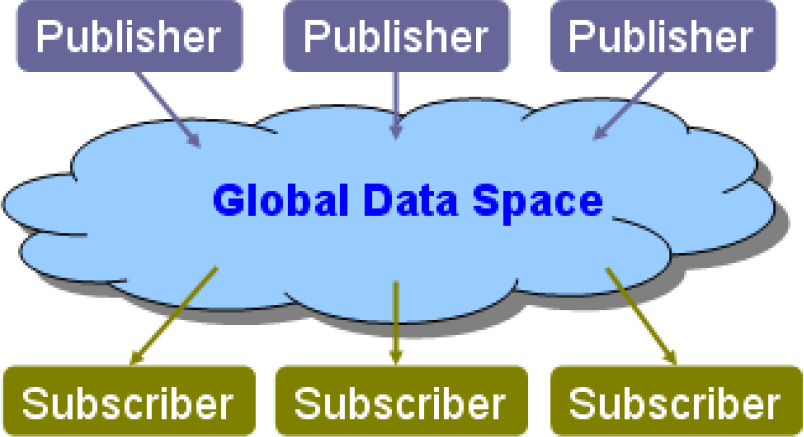
DDS Global Data Space
DDS also defines the Data-Centric Publish-Subscribe (DCPS) model, a topic-based API involving several entities [13] as represented in Figure 3. These entities are described below.

Major DDS entities and their interactions
One of the key features of DDS is the availability of a broad number of mechanisms that allow the management of QoS policies. These policies are configured at the different DDS entity levels (topics, data writers, data readers, publishers and subscribers). Table 1 shows the available parameters for specifying and managing the QoS policies in the current DDS specification. These parameters must be publisher/subscriber compatible under an RxO (Request vs. Offered) contract.
List of most relevant DDS QoS parameters

DDS has been adopted in many application domains. In particular, a few works deal with the use of DDS in factory automation applications. For example, in [14] a modular active fixturing system built with DDS has been presented. Also, DDS is analysed in [37] as a communication backbone for IEC61499 communication SIFBs [18]. Other works analyse the use of DDS in Electrical Substation Automation Systems [38].
3.2. Internal design of the DDS-based Automation Component
One of the major benefits of using DDS as a communication backbone is that it provides a hierarchical set of entities with a rich set of QoS parameters, which, when configured appropriately, may be used for fine tuning the communication needs of the applications. Even though this characteristic makes DDS a very powerful and high performance technology, it may prove complex to use by non-experienced users, especially due to the variety of combinations of QoS parameters. This subsection presents the internal design of a DDS-based Automation Component architecture that includes all the functional operations provided by every component, as well as the necessary entities to use DDS as a communication backbone for factory automation applications. Thus, programmers will be able to create factory applications by connecting Automation components that encapsulate the functionality of factory automation controllers, such as PLCs, robots or IPCs, to the DDS software bus, as shown in Figure 4.

Building factory applications with DDS-based Automation Components
The DDS-based Automation Component is based on a hierarchical skeleton that could be semi-automatically generated with model driven engineering (MDE) techniques. Figure 5 presents the UML class diagram for this component. Application programmers must insert the functionality of the component by instantiating several objects of the FunctionalWrapper class. These objects implement the services that require access to the DDS backbone as described above through objects of the DDS:Topic class. The Figure also shows the hierarchy of DDS classes needed to access the DDS:Topic objects in every component. Finally, according to the type of service, each DDS entity is configured with different DDS QoS policies, as discussed in the following subsection.

UML class diagram for the DDS-based Automation Component
For example, since DDS is capable of managing the distribution priorities of the data inside the Topics: (1) aperiodic communications for delivering sporadic data, alarms and events may be assigned the highest priority levels; (2) periodic data will be distributed by using medium to high priority values, thereby guaranteeing basic update times and (3) non-time-critical communications can be mapped into topics with lower priority values, improving the traditional best-effort paradigm. However, due to the nature of TCP/IP protocols, some QoS aspects will not be enforced but just a hint given to the underlying infrastructure.
3.3. Mapping factory automation communications over DDS
Even though DDS allows a large number of QoS policies to be configured, the authors have tried to simplify the configuration of the middleware by focusing only on those considered most relevant in factory automation applications. A short description of these parameters follows:
This subsection also presents guidelines for specifying the DDS QoS policies in order to map the different types of traffic found in factory automation applications, as identified in Section 2. This kind of application involves different operations, each of them requiring particular traffic flows. Thus, since DDS is a Publisher/Subscriber based technology, all Client/Server operations require mapping into the Publisher/Subscriber paradigm. Efficiency will be lost, but only on the request/response operations, which frequently require lower priorities. This approach allows middleware to be left to deal with the communication requirements. A discussion about how to map factory automation traffic in terms of DDS follows. Table 2 summarizes this mapping.
Recommended QoS parameter values for every kind of factory automation traffic

4. Case study
This section presents a case study that illustrates the application of the above-proposed DDS mapping. It is based on a factory automation cell (see Figure 6) in which four stations assemble different parts over a pallet. More specifically, the assembled final piece is composed of a base, a bearing, a shaft and a lid.

Factory automation cell
4.1. Description of the case study application
The cell is capable of assembling different types of pieces. Individual stations are capable of distinguishing the type of piece by means of a piece code located at the bottom of the pallet and execute different operations accordingly. Each station has a conveyor belt to move the pallet across the station. After correctly processing one piece, the conveyor moves the pallet with the piece to the next station, in order to continue with the assembly process. The four stations involved in the case study are the following:
There is also a supervisory control application that initializes the controllers of the stations at the start-time and monitors the process status at the run-time.
The control application for the factory automation cell has been created with five automation components that encapsulate the functionality of each of the four stations described above, as well as the supervisor.
These automation components have been distributed over three physical devices connected by an Industrial Ethernet, as shown in Figure 7. One device holds the supervisory automation component whereas the other two devices are IPCs that play the role of station controllers. Each IPC contains the software of two automation components that encapsulate one physical station. In the proposed case study Controller 1 holds the Loader and Robot automation components whereas Controller 2 holds the Sealer and Storage automation components.

Topology of the case study application
As shown in Figure 7, there are two industrial communication networks involved in the system: (1) Profibus-DP fieldbus, which is used by the controllers to access the I/O signals in each station in a multimaster configuration and (2) Industrial Ethernet network, which implements the control communication network and links the controllers and the supervisory computer. This is the network in which the DDS virtual bus is implemented.
4.2. Information exchange and mapping into DDS topics
The case study presented above requires both synchronization of the stations in order to follow the processing sequence and delivery of the messages simultaneously to several devices (e.g., the following station and the supervisor). Consequently, an efficient publisher/subscriber technology like DDS seems an adequate choice.
Figure 8 represents the messages exchanged among the automation components that encapsulate the station functionalities of the factory automation cell. These messages are described below. Different colours have been used to represent each type of service.

Information exchanged among the Automation Components via the DDS backbone
Once the piece identification code is read from the pallet at each station, its code and error/status information are published in DDS as one topic (Set) that is used by the next station (Ready) for two purposes: (1) to anticipate the parts required for a specific type of piece and (2) validation. This information is also delivered to be used by the supervisor.
When any station finishes processing a piece, it publishes its code and error/status information by means of a DDS topic (End). This topic informs the next station (Begin) to start its procedure and it also contains information used by the supervisor.
The supervisor may start and stop the stations using two DDS topics with configuration data (Start/Stop). Both of them allow configuration data in the message body to be sent. Internal faults at the stations are communicated immediately to the Supervisor by means of another DDS topic, the so-called General Station Event (GSE), which includes error and status information of the fault.
Table 3 provides a map of the identified services in the described industrial automation environment into DDS. Since GSE represent alarms and events, they are mapped into Aperiodic Station Event (ASE) services whereas Set and End are mapped into Periodic Variables (PV). Both types of services adapt best to the Publisher/Subscriber paradigm as described above. As a consequence, they require a single DDS topic for each variable with the same names (GSE, Set and End). In the case of GSE the supervisor subscribes to a topic shared by several station components (Loader, Robot, Sealer or Storage), which may publish the events. In the case of the Set and End topics, any station component may act as a Publisher, whereas the next physical station as well as the Supervisor may act as Subscribers.
Summary of the mapping into DDS topics and services

Start and Stop operations involve sending configuration information from the Supervisor to the stations in the body of the message. Since these operations do not need a response from the station component to the supervisor, they should be mapped as Request/Non Response (RNR) services. The supervisor component publishes these topics and station components (i.e., Loader, Robot, Sealer and Storage) subscribe to them.
The stations may also require additional information from the Supervisor, such as a code description or the status of any station. These operations are achieved by using Request/Response (RR) services. In this case, two topics are needed: Msg_Req and Msg_Res.
Figure 9 shows some of the topics exchanged among the Supervisor, Robot and Sealer components. This figure is focused on the Robot component and, for the sake of clarity, the figure is not exhaustive: neither are all the topics and nodes depicted nor all connections of the Storage station shown. The boxes represent the automation components that wrap the stations. The direction of the arrows represents whether the application publishes one topic (one outgoing arrow) or is subscribed to a topic (one incoming arrow). Arrows have different colours and styles depending on the type of communication: Red is for ASE, green is for PV, yellow for RNR and blue is for RR. Finally, topics are located in the middle of the figure and are managed by the DDS middleware according to the QoS parameters as described below.
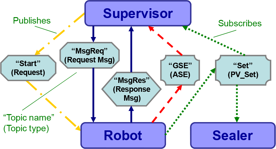
Topics exchanged among the Supervisor, Robot and Sealer automation components
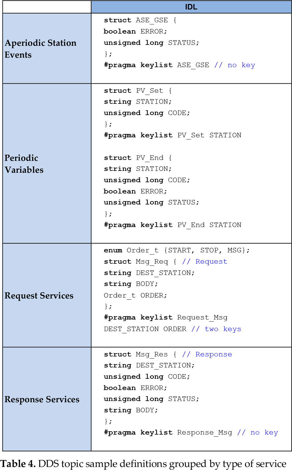
DDS uses a subset of IDL to describe the topics of the applications. Table 4 provides sample IDL interfaces that illustrate how to define the data of the case study in order to distribute them among the nodes of the distributed application for the above-described services. It should be noted that RR and RNR services share the same type for their requests, namely Msg_Req.
DDS topic sample definitions grouped by type of service
4.3. Building the automation components
This section describes the construction of the automation components according to the internal design proposed in Section 3.2. Even though this section is focused on the Robot automation component, it could be easily extended for the other components. Two major points are discussed hereafter: the object hierarchy of the robot component, as well as the values for the most relevant QoS parameters for the DDS entities.
Figure 10 represents an UML object diagram that implements the UML class diagram proposed in Figure 5 for the robot component. The RobotComponent contains two major objects, the RobotWrapper which holds the robot functionality by wrapping its programs and the CellParticipant, which implements an object of a DDS:DomainParticipant class for connecting the RobotComponent to the DDS middleware. All DDS:Topics described above (Set, End, GSE, Start, Stop, MsgReq and MsgRes) are connected to the DDS middleware by means of the RobotPublisher and RobotSubscriber. There are also several implementations of the DDS:DataWriter and DDS:DataReader classes, one for each kind of service defined above (i.e., Aperiodic Station Events – red, Periodic Variables – green, Request Non Response Services – yellow and Request/Response Services – blue).

UML object diagram for the Robot automation component
With regard to the QoS parameter settings, Table 2 summarizes the values assigned to the different DDS QoS parameters. Below is a brief justification of the chosen values:
The
The
The
5. Conclusions and future work
This work illustrates how to use DDS as a middleware virtual bus for connecting industrial controllers at the control layer of the automation pyramid. Every physical device is encapsulated by means of a generic software component, the so-called Automation Component, capable of accessing (reading and writing) information (Topics in DDS terminology) from the virtual bus. Assuming that the underlying network infrastructure is capable of enforcing the selected QoS policies, the use of a unique middleware specification if properly configured, may solve all communication needs for factory automation applications becoming a real communication backbone.
This paper also proposes an internal design for the Automation Component as well as a mapping for the most frequent operations in factory automation applications. This mapping distinguishes among different types of services and provides guidelines to configure the values of the DDS QoS parameters. The use of the proposed mapping is illustrated by means of a case study consisting of a factory automation application.
The authors are currently working on the creation of a basic IEC61499 function block set [37] so that they may constitute structural components from which distributed factory automation applications may be created on top of DDS.
Footnotes
6. Acknowledgments
This work has been financed in part by the Spanish Ministry of Economy and Competitiveness (MINECO) under project DPI2012-37806-C02-01; by the Basque Government through the S-PE11UN061 SAIOTEK project and by the University of the Basque Country (UPV/EHU) through grant EHU11/35.