
Abstract
The article presents a software architecture to optimize the process of prototyping and deploying robot controllers that are synthesized using model-based design methodologies. The architecture is composed of a framework and a pipeline. Therefore, the contribution of the article is twofold. First, we introduce an open-source actor-oriented framework that abstracts the common robotic uses of middlewares, optimizers, and simulators. Using this framework, we then present a pipeline that implements the model-based design methodology. The components of the proposed framework are generic, and they can be interfaced with any tool supporting model-based design. We demonstrate the effectiveness of the approach describing the application of the resulting synchronous dataflow architecture to the design of a balancing controller for the YARP-based humanoid robot iCub. This example exploits the interfacing with Simulink® and Simulink® Coder™.
Keywords
Introduction
In the past few decades, robotics has experienced a continuous shift from applications in constrained industrial environments to those involving autonomy, interaction, and collaboration with external agents. The adaptation of the robotic devices to new tasks often presents big challenges in both cost and time. Thus, the capability of prototyping a new controller and rapidly deploying it to the target robotic device is becoming more and more paramount. The canonical approach to develop a robotic controller can be summarized in two distinct phases. 1 In the first phase, the robotic controller is synthesized, tuned, analyzed, and possibly tested in a simulated environment. Arbitrarily complex models of the controlled system are typically exploited. In the second phase, the controller is ported to the real device, tuned again and executed. Each minor change to the controller requires iterating this entire process from start, and a lot of effort is spent to minimize manual operations.
Model-based design 2 (MBD) is a methodology that emerged to deal with the challenges introduced by the need to continuously improve complex systems. MBD aims to simplify the development by providing a common environment shared by people of different disciplines involved in the different design phases. 3 Later changes of the original design either due to early mistakes or requirements modifications are easier to propagate, therefore time and cost of the development can be reduced. 4 A characteristic of the MBD is that the iterative process of the continuous improvement is performed with unified visual tools, typically based on dataflow programming languages and frameworks. The dataflow naming originates from the view of programs as directed graphs of computations, where the data flows between their components. 5 Controllers are usually described and analyzed using block diagrams, and the view offered by dataflow programming, composed of nodes and edges, naturally translates to blocks and signals. The analogy between graphs and block diagrams makes MBD particularly appropriate for controller design. A typical implementation of MBD consists of the following stages:
Plant modeling: creation of a mathematical description of both the dynamics of the controlled system and its environment.
Controller prototyping: implementation of the operational aim of the controller acting on the plant model.
System simulation: assessment of the controller performance in a simulated environment containing the plant model.
Controller deployment: adaptation of the resulting controller to run online on the controlled system operating in the real environment.
In the market, there are many available open-source and commercial software that implement the specifications of MBD. Most of them belong to a broader category of tools that fulfill the paradigm of actor-oriented programming 6 (AOP). Contrarily to object-oriented programming (OOP), where data structures interact via procedure calls, in actor-oriented languages concurrent objects are the first-class citizens. These objects are also called actors and they communicate with each other via predefined channels. Actors have well-defined interfaces that abstract their internal state and define constraints on how they can interact with the outside. The interaction between actors is never direct as the channel mediates it. In this way, the actors are independent entities that are not directly connected with other actors. The definition of AOP is very broad and many models of computation 7 can be identified to categorize the nature of the interaction between actors and channels. Each of these models is characterized by constraints in their execution, typically in the form of internal computation, internal state update, external computation, and type of communication between actors. Among all the available models, synchronous dataflow 8 is particularly suited for the design of robotic controllers. The computations performed by this model are triggered by the availability of new input data and the connections between actors are buffered. Examples of tools belonging to this domain are Simulink®, 9 Xcos, 10 Modelica®, 11 and LabVIEW™. 12
The application of MBD to robotic controllers development can narrow the gap between control engineers, used to approach systems with block diagrams, and software engineers, used to procedural and OOP. However, this approach is not exempt from the complications introduced by system integration, which often introduces time-consuming obstacles. Particularly for what concern robotics, AOP languages by themselves are not the final solution. In fact, OOP still has a central role in the development of low-level algorithms. The aim of these actor-oriented languages is not substituting OOP, but complementing it. In fact AOP is more suitable to target the creation of applications that belong to higher abstraction layers, implementing a design principle compatible with the separation of concerns. 13,14 It represents a valid choice to ease the interconnection of self-contained black-box functionalities, which represent the building blocks of any robotic controller.
In this work, we propose a software architecture composed of a framework inspired by AOP and a pipeline for its application to robot controllers design. The framework intends to reduce the effort spent on system integration while minimizing both code and functionality duplication. The pipeline implements all the MBD stages, and it aims to minimize the controllers lead time while automatizing as much as possible the prototyping and deployment processes. Rapid prototyping and continuous deployment are achieved interfacing the framework respectively with Simulink and Simulink® Coder™. 15 Simulink provides out-of-the-box a wide library of black-box functionality exposed as blocks and also allows to be extended and integrated with external algorithms. Its status of visual programming and debugging is very mature and well-documented. Simulink Coder provides the automatic code generation capability that aids the implementation of the deployment stage of MBD, removing the need to port or adapt the controller to another domain before being executed in the target platform. 16
Despite our tools selection, the framework has been designed in such a way to simplify the integration with other existing actor-oriented frameworks. The logic of the presented black-box functions (developed in OOP) is independent of them. This design allows to effectively separate the two programming domains while exploiting the best features from both.
More specifically, the work presented in this article is based on a previously introduced framework. 17 From the status described in that work, the underlying software architecture considerably changed, but a big effort was spent to maintain as much as possible the same user experience. The whole-body interface layer proposed in the original work has been entirely removed, moving the responsibility of the robot abstraction to the middleware layer. Moreover, most of the improvements detailed in the same study have been adapted to the new architecture and implemented. Beyond a radical architectural advancement, the main extension presented in this work is the fulfillment of the automatic code generation support, fundamental to complete the implementation of MBD.
The article is structured as follows. First, we list tools and frameworks belonging to AOP and implementing the MBD pattern, and define a common terminology used throughout the article. Then, we present the architecture of the proposed software framework and outline how we implemented AOP for robotic controllers design. Successively, we describe how the proposed framework can be exploited to obtain a pipeline that implements the typical stages of MBD. We present a development cycle example for a balancing controller that targets a humanoid robot. We proceed by discussing the current limitations of this workflow and future improvements. Finally, we draw conclusions.
Background
Related software
MBD is a methodology that covers many software layers. Following a top-down view, the conventional unified tools typical of MBD usually share the following features:
support to automatically generate real-time code from a model,
present a graphical interface to visualize a model,
serve an engine to initialize the directed graph of computation,
provide a set of solvers to compute the output of each model element,
include a library of default black-box functions, and
offer a set of application programming interface (API) for interfacing with its engine.
Providing a complete taxonomy of the existing tools and frameworks is not a trivial task. To simplify the analysis, we limit the overview to frameworks that use the synchronous dataflow model of computation, ignoring those that also support concurrent actors. Considering the scope of the current work, we separate the existing solutions in two categories: hybrid and discrete-only.
Hybrid tools are the most generic and complete, they typically allow performing both continuous and discrete simulations. Since they provide solvers for each of the two domains, hybrid tools can execute both offline simulations of continuous ODE systems and their discrete equivalent which is compatible with real-time usage.
Discrete-only tools, instead, target only discrete-time systems, and their execution is limited to call an equivalent
Given these definitions, engines that belong to the hybrid group are Drake, 18 OpenModelica, 19 and the commercial software Simulink, Dymola®, 20 and LabVIEW. 12 Excluding Drake, all the others are unified visual tools which fully enter into the MBD framework. Simulink, in particular, is the engine that became the de facto standard for MBD. It implements all the MBD stages providing great flexibility and very simple user experience.
Other available engines are represented by those that emerged in the context of software engineering for robotics, all belonging to the category of the discrete-only tools. These types of engines are typically designed to support the development of software that runs in real time on a robotic platform, and so they do not support simulation-specific features such as continuous-time system modeling. Examples of this software are Stack of Task’s Dynamic Graph, 21 Genom3, 22 OpenRTM, 23 and Orocos. 24 A features comparison of the tools listed in this section is presented in Table 1.
For what concerns the deployment stage of MBD, we can identify few suitable frameworks that provide support of automatically generate code. The scope of this process is to convert a model prototyped as a directed graph to a low-level procedural representation. Nowadays, automatic code generation is a standard feature of the MATLAB system. The Simulink Coder toolbox allows generating optimized C and C++ code from a Simulink model, and it provides support to customize the sources injecting custom code during the generation process. Other frameworks that are worth mentioning are most of the software suites based on the Modelica 11 language, which typically support generating low-level code from their models.
Comparison of available synchronous dataflow frameworks.a
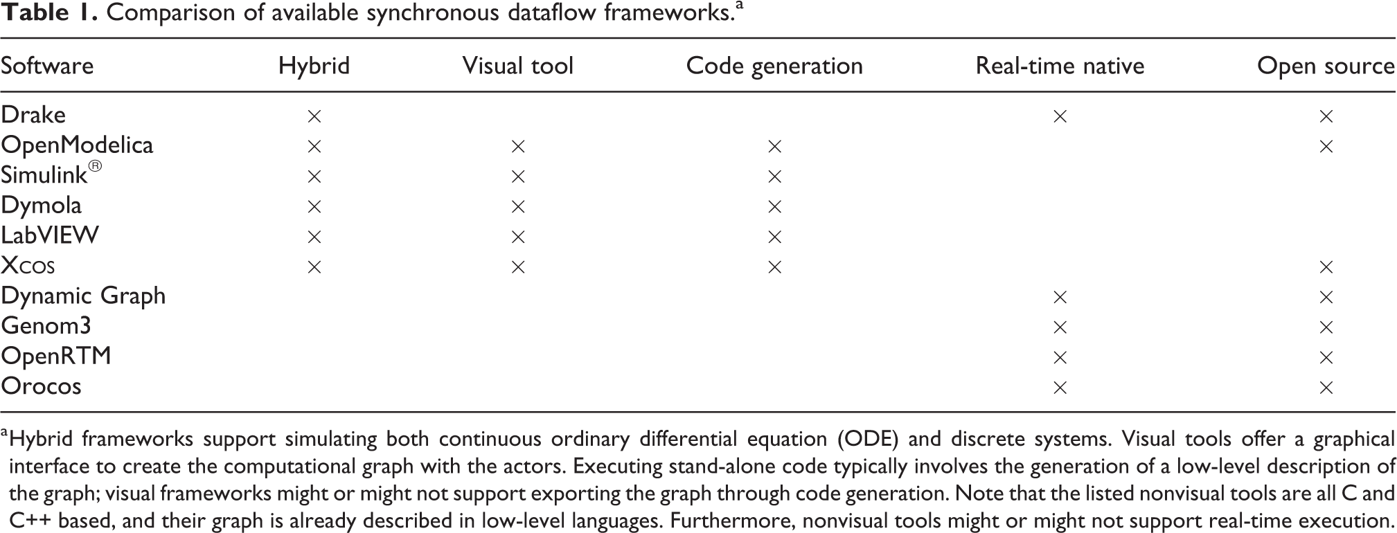
a Hybrid frameworks support simulating both continuous ordinary differential equation (ODE) and discrete systems. Visual tools offer a graphical interface to create the computational graph with the actors. Executing stand-alone code typically involves the generation of a low-level description of the graph; visual frameworks might or might not support exporting the graph through code generation. Note that the listed nonvisual tools are all C and C++ based, and their graph is already described in low-level languages. Furthermore, nonvisual tools might or might not support real-time execution.
The functional mock-up interface 25 (FMI), despite being outside the categorization described above, is still relevant to this overview. FMI is a standardized interface widely used in industry for model-based development. It is a feature-rich and production-grade tool with a clear standard, constantly improving at each release but, as most of the tools listed in this section, it was not available when we started the development of our software stack. In any case, its adoption in its current form would not be possible due to the lack of the support of vector messages between actors, shortcoming that will be removed in the upcoming version of the standard.
Other interesting frameworks for controllers design which are related to the cited engines are the Robotic Toolbox 26 and the Robotic System Toolbox. 27 The latter, particularly, is one of the few unified framework that fully implements MBD specifically for robotic controllers. It is based on the ROS 28 middleware, and it implements many of its features. However, the support of kinematics and dynamics has been added only recently, and it lacks the possibility to be extended to interfacing with third-party robotic libraries.
Terminology
The majority of the hybrid and discrete-only software listed in the “Related software” section share a software architecture composed of similar components. In view of the AOP architecture used in this work, we will make use the following terminology, illustrated in Figure 1:
Blocks are elements that provide self-contained functionality. They wrap algorithms exposing a black-box interface composed of inputs, outputs, and parameters.
Ports are virtual elements associated to block inputs and outputs. They store information to identify which kind of data is supported by the block (typically size and type).
Signals are the elements that connect ports of different blocks. When two ports are connected, they share their data.
Engines control the channel through which the blocks communicate. Engines typically create the computational graph and assign the blocks execution order. They also collect the block outputs and propagate them to the handled channel. They usually provide graphical tools to visualize blocks and help their interconnection by creating signals between them.

Visualization of the implementation of an actor: the block.
These terms naturally translate to the definitions of the AOP framework: blocks map to actors, signals map to channels, and ports represent the interface between actors and channels.
Framework software architecture
This section describes the software architecture of the proposed framework. Firstly, the factory pattern and the plugin concepts are introduced. Their combined usage has direct applicability within an AOP context. Secondly, we describe in detail the two components that form the framework:

Unified modeling language (UML) diagram of the main classes part of the proposed architecture. The
Factory pattern and plugin libraries
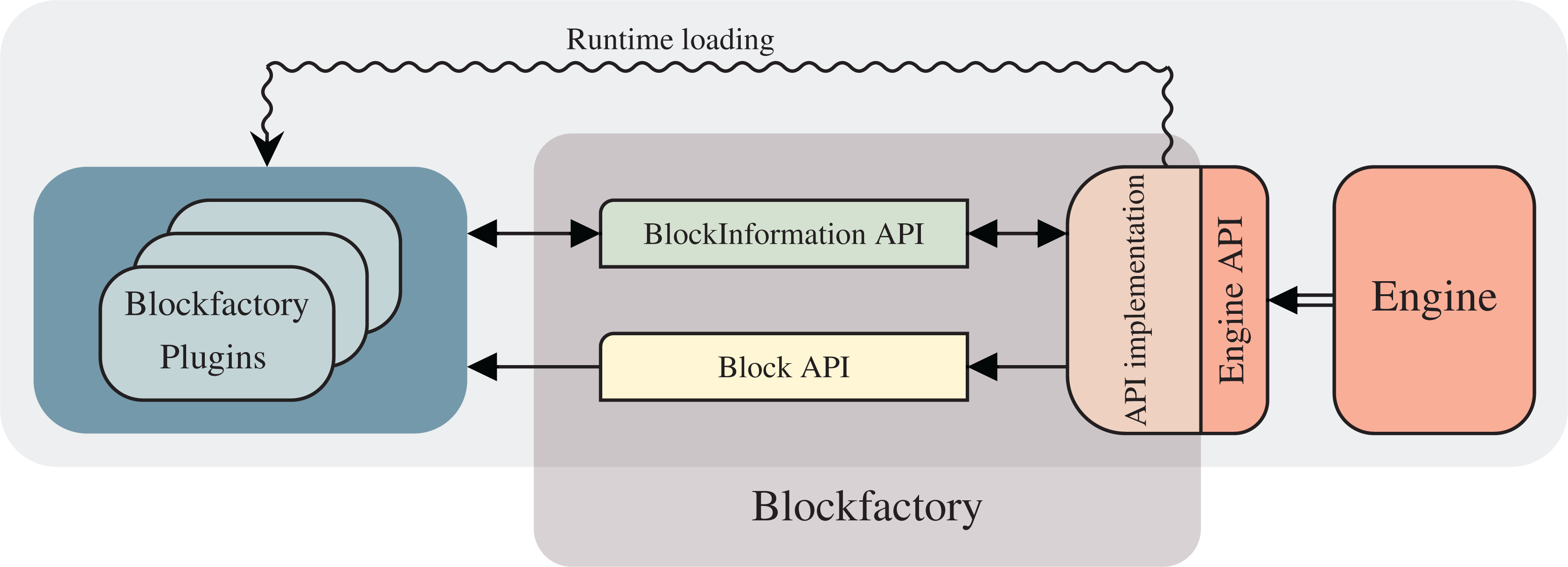
Third-party engines typically offer a set of APIs that can be used to integrate external software inside their framework. To detach effectively the block implementations from the third-party engine, the combination of the factory pattern and dynamically loaded plugins represents one of the canonical solutions. 31 With the factory pattern, objects are created from a factory function without the need to specify their class. Typically, a label or identifier is associated with this kind of objects, and only this information is required during their instantiation. Unfortunately, this is not enough to achieve the separation between engines and blocks, because the factory function only hides their allocation and the engine still needs to link against their implementation. This shortcoming can be overcome with plugin libraries dynamically loaded during runtime. In this case, the engine needs to have two information: the label associated with the implementation of the block and the name of the shared library that contains it. Once the plugin is dynamically loaded, the engine can instantiate block objects using a factory function without knowing anything about the class that implements them. Then, it can call their functionality through the common interface. The implementation of block classes is not constrained to any model of computation of AOP. In the most general form they can be asynchronous and concurrent.
The combined architecture of factory and plugins represents a natural implementation of AOP. In fact, the limitation of the engine to access the functionality of the blocks through their exposed abstraction layer enforces one of the key characteristics of actors: the exposure of a well-defined interface.
For what concerns robotic controllers, the separation layer introduced by the plugin-based factory pattern provides a great help in system integration. In fact, since the plugin libraries containing the blocks are engine-agnostic, they can be loaded from each engine without the need to recompile them. This means that a controller prototyped with one engine can load the same library of the deployed controller. The code duplication is hence minimized and the robustness of the system is improved because the logic of the blocks is shared. Another benefit of this architecture to the system integration is about dependencies. The stand-alone plugins can link against any third-party library without the need to operate on the layer specific to the engine.
BlockFactory
The concepts defined by AOP are implemented in a tool called
To obtain engine-agnostic blocks, the 1 to be abstracted. For this scope,
Software architecture outline.
The interfacing with third-party engines can be achieved in two steps. Firstly, their own API or callbacks need to be implemented for loading during runtime the plugins containing the block’s logic. Secondly, to provide blocks the information from the engine they need, the
The actor-oriented applications that can be built with
Whole-body toolbox
WHOLE-BODY TOOLBOX is a C++ plugin library that exposes canonical algorithms and utilities commonly used to develop robotic controllers, such as rigid-body dynamics algorithms and communication capabilities with robotic devices mediated by middlewares. These functionalities are wrapped as block entities, and they can be loaded independently by all the third-party engines supported by
For historical reasons, the middleware we actively support is YARP. 32 Our main target platform is the iCub humanoid robot, 33 even though all YARP-compatible real and simulated robots are supported out-of-the-box. As an example, a previous work 17 showed a simulated whole-body controller running on both iCub and Walkman 34 robots.
Historically, WHOLE-BODY TOOLBOX was developed for whole-body control, 35 hence the name. In its last revisions, it became a generic robotic toolbox that can be used for any type of controller. The blocks implementing dynamics and kinematics algorithms are mainly based on iDynTree 36 and do not depend on any middleware. They can be used also with robots which are not YARP-based, outsourcing, in this case, the interfacing with the target platform to third-party plugin libraries. The only requirement for using the provided algorithms is the availability of an URDF description of the robot to control. 37
A complete software stack for robotic controllers typically involves the interaction with a physic simulator. The robotic simulator we chose to support is Gazebo. 38 The interaction between Simulink and Gazebo follows a co-simulation pattern, where the former is the master that issues forward step commands to the physic engine at each simulation step. The controller transparency between the real and the simulated robot is achieved by exposing the same network interface exploiting the abstraction layers provided by the YARP middleware. In the case of the simulated robot, the implementation of these interfaces are provided by Gazebo YARP Plugins. 39
The toolbox also provides generic utilities for robotic applications, such as discrete filters, Cartesian trajectory controllers, 40 and quadratic programming solvers based on qpOASES. 41
The pipeline
In the “Framework software architecture” section, we introduced the proposed framework, described its architecture, and discussed how its components interact with each other. In this section, we will describe the pipeline that implements MBD from the point of view of the control engineer, detailing how it is practically used and how the components of the framework relate to each step of the development.
The proposed pipeline implements all the four stages on which the MBD pattern is derived. We will demonstrate a practical usage showing the steps to rapidly prototype and deploy a balancing controller, 42,43 executed on the humanoid robot iCub. 33 A simplified overview of the theory behind the controller is reported in the preceding work. 17 Since we managed to maintain the compatibility of the controllers designed with the previous architecture, the experimental results of that study that use Simulink correspond to the prototyping phase of this pipeline. As explained more in detail below, thanks to the abstraction between the controller and the robot provided by the YARP interfaces, the pipeline includes few intermediate steps in addition to the stages defined by MBD.
The first stage of MBD is plant modeling. For controllers applications, the plant is typically composed of the robot and the environment where it operates. In our case, the model of iCub is represented by an URDF file, which stores its kinematic and dynamic properties. The model of the robot is generated semi-automatically from its computer-aided design, solution that allows obtaining a very detailed description of the robot. For what concern the environment, we use the default empty world provided by the physic engine running inside the simulator. The same applies to the interaction between the robot and the environment.
The implementation of the remaining stages of MBD is illustrated in Figure 4. The first row shows the prototyping phase of the pipeline and the second one shows the deploying phase. Referring to the figure, the depicted steps serve as follows:
This first step implements the controller prototyping stage of MBD. The controller is designed in Simulink using the default system blocks and the blocks provided by WHOLE-BODY TOOLBOX. In this case, when the user drops a block in the model, the S-function contained in
When the controller is ready, it can be executed on the simulated robot model. WHOLE-BODY TOOLBOX provides a block for interfacing with Gazebo, synchronizing it with the simulation loop running in Simulink. This step provides the means of the system simulation stage.
In this additional third step, the control designer has the possibility to connect the controller, still running in Simulink from an external machine, to the real robot. Since the controller now needs to run in a real-time setting, the block used to interface with the simulator is substituted with a block that enforces the simulation loop to be synchronized with the real clock. Measurements and reference signals are gathered and streamed in real time.
Reached this point, the controller is already functional on both the simulated and the real robot. The last controller deployment stage starts with step 4. Exploiting the capabilities of Simulink Coder, the oriented graph visually created in Simulink is translated to an automatically generated C++ class. In our software architecture, Simulink Coder is handled as another engine (as illustrated in Figure 2), and a different implementation of the
This step in equivalent to step 2. In this case, though, the automatically generated controller is executed on the simulated robot.
Similarly, this step is equivalent to step 3 with the automatically generated controller.
The real deployment to the target platform is represented by this last step. Until now, the controller always ran from the external machine, communicating to the real robot through the network, exploiting the YARP observer pattern.
31
The automatically generated class of the controller and the
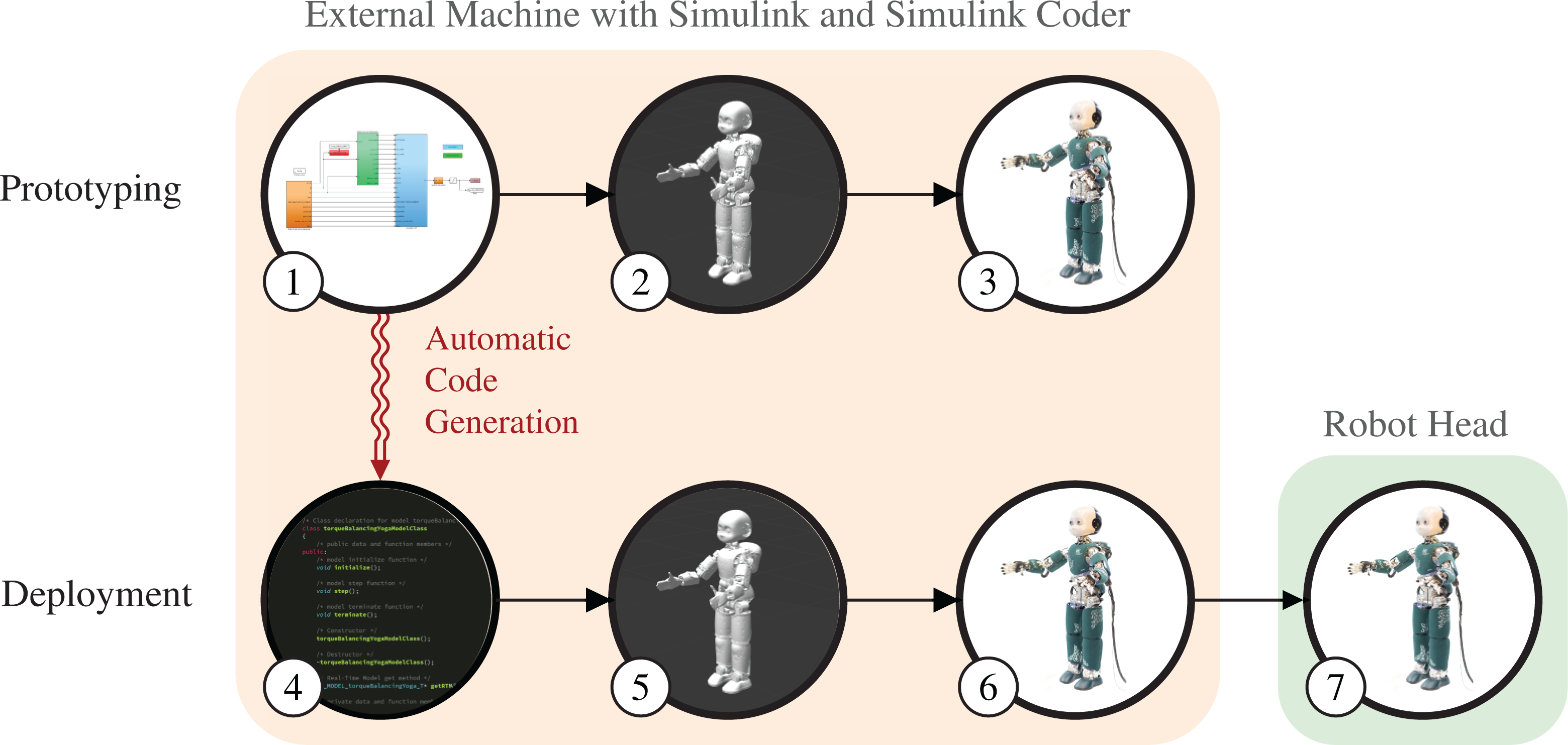
Overview of the pipeline implementing model-based design. The prototyping phase, in the first row, assumes the availability of a model of the robot. In step 1, a Simulink® model of the controller is created. In step 2, the controller is tested in the Gazebo simulator using the robot model. In step 3, the same controller used in simulation is tested on the real robot, leveraging the robot transparency provided by exploiting the same YARP interfaces. All the computations of this phase are executed from an external machine running Simulink. The communication with the real robot is achieved through the YARP middleware. The second row illustrates the deploying phase. Exploiting Simulink® Coder™, in step 4, C++ code is automatically generated from the Simulink controller. Steps 5 and 6 perform the same tests of the previous phase from the same external machine, respectively, on the simulated and the real robot. This time, though, the autogenerated controller is executed. Eventually, in step 7, the controller is deployed to the computer in the robot head and runs stand-alone.
In this example, the controlled robots—simulated and real—refer to the same kinematic structure. One may wonder which modifications are necessary in this new architecture to run the controller on a robot endowed with a different number of degrees of freedom. One of the new features of WHOLE-BODY TOOLBOX is the presence of a configuration block, where it is possible to specify runtime information such as the name of the URDF model, the names of the controlled joints, and the name of the robot used to set up the YARP context. Excluding edge cases, this is enough to make controllers independent from the robot.
Limitations and future work
BlockFactory
The dataflow framework
In its current state, the block interface is modeled to be a stateless system. The engine can only trigger the evolution of a block state by calling its
The FMI
25
represents a common standard as an alternative to the provided interfaces. Instead of a complete substitution, though, being able to expose blocks in their counterparts called functional mock-up units can be a valuable addition. This would open the interoperability with a plethora of tools that already support FMI, improving the integration of the models designed with
Whole-body toolbox
WHOLE-BODY TOOLBOX currently grounds the interfacing with robots on the YARP middleware, and we are aware that there are not many existing YARP-based robots. Despite implementing the YARP interfaces for a new platform is not an insuperable task, it might limit the applicability of this pipeline. Going in this direction, a native implementation of the more common ROS middleware would enlarge the adoption of the proposed tools. A proof-of-concept of an ROS plugin implementing its publisher–subscriber pattern is already available. 44 On the same line, allowing to install the WHOLE-BODY TOOLBOX without its YARP component would be another possible improvement. In fact, the majority of the blocks are middleware-agnostic, and they could be already used in systems without any middleware installed. For instance, many use cases might benefit from the included algorithms for rigid-body dynamics.
The current support of simulating a kinematic structure consists of a co-simulation setup between Simulink and Gazebo that communicate through YARP messages, thanks to the Gazebo YARP Plugins. This entire system worked well for us in the past; however, its use is not as straightforward as it could be. In fact, to obtain a correct synchronization between the two simulators, all the components of this system should be started passing extra options. To simplify this process, it would be beneficial embedding the physic simulator inside a new block, treating it as a regular node of the graph. In this way, the synchronization could be greatly simplified taking advantage of the information available from being executed as part of the computational graph. This would also enable to execute headless simulations and allow us to open the graphical user interface only if visual feedback is required.
A limitation of WHOLE-BODY TOOLBOX that might restrict its applicability to generic tasks is the lack of maturity of the robotic perception stack. The main scope of our applications is balancing and locomotion; therefore, we always ignored perception and focused mainly on dynamics. Our controllers currently operate only on flat terrain, where perception is not required. However, creating new specific blocks to retrieve sensory data would be straightforward. An improved perception can then allow controllers to handle more structured scenarios that can be already simulated in Gazebo inserting the robot model into a structured world.
In the long run, we would like to add the support of existing machine-learning frameworks to embed networks and function approximators into our robotic controllers. Furthermore, we are planning to introduce the possibility to export controllers with an interface that exposes a set of parameters which would allow applying reinforcement learning algorithms.
Pipeline
The description of the pipeline reported in the previous section offers a general overview of its functionalities. However, it hides few caveats which might not be straightforward. In step 2, obtaining a model that can be effectively actuated in Gazebo requires tuning its PID gains. Finding a proper configuration is not straightforward and many iterations are necessary. Furthermore, this process has to be repeated again in step 3, when the controller is executed on the real robot. Once the right gains have been properly found, they can be reused in steps 5 and 6. However, these low-level configurations are not strictly specific to this pipeline. In fact, they are related to the YARP implementation of the robot, and these parameters are meant to be abstracted by YARP interfaces.
Similarly, it is interesting to analyze the factors that might differ between running the autogenerated controller from the external machine and from the onboard device of the robot. The communication between the controller and the robot—typically consisting of sensor measurements and references—are mediated in both cases by the transport layer handled by YARP. In the first case, since the controller is running in an external machine, the exchange of data occurs through the network transport layer. This type of data transfer introduces overhead and delays that might affect the performance of the controller. Deploying the controller to the onboard machine provides a great opportunity to mitigate this problem. However, this is not exempt to side effects. In fact, controllers are very sensitive to time delays and dealing with them is yet an open problem in many applications. Assuming that the same gains can be applied might hold surprises. In our experience though, controllers did not need any tuning. In any case, moving the computation of fundamental tasks such as motion control as close as possible to the actuators offers a tremendous possibility to enhance system robustness. Furthermore, the deployed controller is an optimized version of the one executed in Simulink. If the rate of the controller is slower than the rate of the robot measurements and the actuation bandwidth, the gain of speed might allow increasing the controller frequency, which is typically related to better performances.
A current limitation of the autogeneration process is how controller parameters stored in Simulink are handled. With the current
Conclusions
In this article, we presented a rapid prototyping and deployment architecture for robotic controllers based on the principles of MBD. The architecture is composed of a framework and a pipeline.
Developing and maintaining a controller in pure C++ is typically extremely demanding, and even minor architectural changes might require a considerable effort. In light of the fast prototyping aims, developing controllers using visual tools and then automatically generate optimized C++ code represents a great speedup.
As first component of the framework, we presented the actor-oriented tool
Different kinds of robotic controllers are typically based on a limited set of elemental functionalities, and complex logic can be achieved by their composition. In this work, as second component of the framework, we presented WHOLE-BODY TOOLBOX, a collection of black-box functions for robotics representing the building elements of generic robotic controllers. This toolbox wraps a number of existing open-source projects belonging to the categories of robotic middlewares, rigid-body dynamic libraries, and mathematical optimization tools.
These two projects serve as the primary components of the proposed pipeline to rapidly prototype and deploy robotic controllers. In particular, the presented pipeline implements the rapid prototyping capability—idiomatic feature of MBD—by interfacing with the Simulink engine. The rapid deployment, instead, is achieved exploiting the automatic code generation support provided by Simulink Coder. We explained step by step how the entire process works, detailing how the stages of MBD have been implemented.
Ultimately, we explained the shortcomings of the current status of both the components of the presented framework and the resulting pipeline, and our plans to address them. The present condition of these projects is the outcome of many years of development, during which the architecture often changed and gave us the possibility to learn from our mistakes. Despite these continuous changes, a big effort has been spent to keep the experience of the control engineers that use this framework as consistent as possible. As attempted in the previous papers, we tried to be as critic as possible to our choices, being aware that the presented pipeline still has a big room of improvements.
To conclude, we would like to remark that the development of all the presented tools followed from their beginning an open-source and community-driven approach. From one hand, we could have never achieved the current development status and our results if we could not interface with existing open-source software such as middlewares, simulators, and libraries. We are grateful to the entire robotic community to provide and maintain them over time. From the other hand, collaborations with other research institutes—mainly belonging to the community built around the iCub humanoid robot—helped us to improve the robustness of the entire framework using it within different contexts. A great contribution, as an example, regards the interfacing with MATLAB. In fact, due to licensing limitation, we cannot test the pipeline thoroughly with many versions, and also the application of continuous integration pipelines presents many restrictions. A wider user base with diverse setup helped us debugging problems we would probably have never encountered.
Footnotes
Authors’ note
The content of this publication is the sole responsibility of the authors. The European Commission or its services cannot be held responsible for any use that may be made of the information it contains.
Declaration of conflicting interests
The author(s) declared no potential conflicts of interest with respect to the research, authorship, and/or publication of this article.
Funding
The author(s) disclosed receipt of the following financial support for the research, authorship, and/or publication of this article: This was financially supported by the European Union’s Horizon 2020 research and innovation program under grant agreement no. 731540 (An.Dy).