
Abstract
This paper focuses on the modelling and control problems of a self-propelled, multimodal amphibious robot. Inspired by the undulatory body motions of fish and dolphins, the amphibious robot propels itself underwater by oscillations of several modular fish-like propelling units coupled with a pair of pectoral fins capable of non-continuous 360 degree rotation. In order to mimic fish-like undulating propulsion, a control architecture based on Central Pattern Generator (CPG) is applied to the amphibious robot for robust swimming gaits, including forward and backward swimming and turning, etc. With the simplification of the robot as a multi-link serial mechanism, a Lagrangian function is employed to establish the hydrodynamic model for steady swimming. The CPG motion control law is then imported into the Lagrangian-based dynamic model, where an associated system of kinematics and dynamics is formed to solve real-time movements and, further, to guide the exploration of the CPG parameters and steady locomotion gaits. Finally, comparative results between the simulations and experiments are provided to show the effectiveness of the built control models.
1. Introduction
The research into land-water propulsors (i.e., amphibious robots) tends to attract engineers due to their fascinating locomotion agility and high performance [1–6]. Their potential applications involve near-shore observatories, search-and-rescue missions and amphibious reconnaissance, etc. In view of engineering implementations, amphibious robots typically adopt wheel-driven [7], legged-type [8] or wheel-leg hybrid mechanisms [9] for locomotion on land. Others may mimic snakes to crawl on land [2,10,11]. The legged-type and snake-like mobile mechanisms are complex, with maintenance problems and partially unexplored sophisticated approaches. The wheel-driven mechanism is relatively more mature and simpler to design and control, which is broadly suitable for uncritical environments. For underwater locomotion, amphibious robots generally utilize propeller impetus [4,9], snake-like anguilliform swimming [2,10,11] or fish-like fin actuators [1,5,12]. The former two offer slower locomotion speeds and less efficient propulsion. As a fast, efficient and high-mobility underwater propulsor, fish-like swimming takes advantage of conventional rotary propeller-based propulsion, which achieves impressive propulsion efficiency by coordinated oscillations of the body and/or fins. As a distinctive feature, a dolphin propels itself by dorsoventral oscillations as distinct from the oscillations of fish tails, which are confined to the horizontal plane. Remarkably, dolphins display superior performance in terms drag reduction, swimming hydrodynamics and manoeuvrability.
In synthesizing the motion characteristics of both ground mobile robots and underwater robots, this paper mainly presents a novel amphibious robot called “AmphiRobot-II” with a pair of bio-inspired wheel-propeller-fins. It is an improved version of the AmphiRobot-I developed in [12]. As shown in Figure 1, mechanically the robot is composed of a head with wheel-propeller-fins, three fish-like propelling units and a flapping caudal fin. When moving on land, the robot implements wheel-based movements, whereby the wheel-propeller-fins function as wheels; when swimming in water, the robot performs fish-like (lateral oscillations) or dolphin-like (dorsoventral oscillations) propulsion, where the wheel-propeller-fins function as pectoral fins. Specifically, the robot takes fish-like swimming as the primary underwater propulsor by utilizing the travelling waves of body undulation transmitted from head to tail. That is, several fish-like oscillating hinge joints (J1–J4) comprise the drive mechanism (yaw control) while coordinated with the pectoral fins (pitch control). A specially-designed swivelling mechanism is further designed to rotate the posterior body by ±90° (roll control) to switch gaits between fish- and dolphin-like modes.
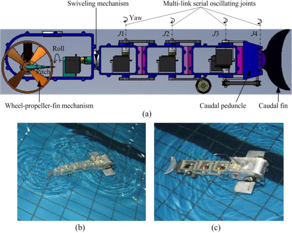
Mechanism design of AmphiRobot-II. (a) Concept design. (b) Fish-like swimming mode. (c) Dolphin-like swimming mode.
To generate a fish body wave, Lighthill proposed a carangiform propulsive wave equation in the 1960s [13]. In 1996, Barrett et al. developed an experimental model of the RoboTuna's swimming kinematics in terms of a set of seven key parameters that can determine swimming performance [14]. These sine-based approaches use simple time-indexed sine-based functions for generating travelling waves. Besides the disadvantages of poor anti-interference capability, abrupt modifications of control parameters (in terms of wavelength, oscillating frequency and amplitude, etc.) will lead to a discontinuousness of propulsive waves, which in turn will produce non-smooth trajectories. In recent years, neurobiological studies have indicated that vertebrates have neural circuits – namely, central pattern generators (CPGs) – in their spinal cords that can produce patterns of the oscillations necessary for locomotion. Due to its robustness and the limit cycle property [16], the CPG-based control approach can be employed well to produce rhythmic movements, such as legged walking, flying and swimming. In addition, a robot swimming underwater will interact with the surrounding fluid. The strong coupling and nonlinearity between them mean that highly effective motion control remains unresolved.
In this paper, CPG-based locomotion control in conjunction with Lagrangian dynamics is employed to tackle the aquatic propulsion of AmphiRobot-II. In particular, the integration of the Lagrange dynamics and the CPG-based control guides the search for CPG parameters, steady locomotion gaits and preliminary validation, greatly facilitating the creation of versatile gaits. As a result, the amphibious robot equipped with wheel-propeller-fins successfully possesses more novel amphibious gaits, enhancing its motion ability and possible operations.
The rest of the paper is organized as follows. In Section 2, the adopted CPG-based locomotion control is briefly described. The formulated Lagrangian dynamics are detailed in Section 3. The simulated and experimental results are provided in Section 4. Finally, Section 5 concludes the paper with an outline of future work.
2. CPG-based multimodal locomotion control
To estimate the oscillation property of a fish body, Lighthill's elongated body theory has been widely used to generate a propulsive travelling wave. Many other aspects of fish-swimming behaviour have been studied to shed light on the propulsion mechanism, which demonstrates an implied undulatory wave travelling from head to tail with increasing amplitude. Meanwhile, neurobiology studies reveal that fundamental rhythmic motor patterns in locomotion are generated by CPGs in various organisms. CPGs are networks of neurons that can produce coordinated oscillatory signals without oscillatory inputs from sensory feedback or higher control centres, which have become widely used in robotics recently [15–18]. The CPG-based controller, in particular, has the quality of distributed control and the ability to deal with redundancies and fast control loops, as well as permitting the modulation of locomotion by simple control signals [15]. As such, it is well-suited for locomotion control in dealing with multi-articulate or multi-DOF-related applications. Since the swimming of fish relies on rhythmic activities through oscillations of a multi-joint body and fins, a CPG is an appropriate tool for modelling the kinematics of the underwater locomotion of the amphibious robot. As the kernel of the CPG model, a phase oscillator with controlled amplitude based upon the Kuramoto model is utilized to achieve the synchronization of multiple oscillators so as to ensure coordinated movements of multiple joints [19,20]:

where
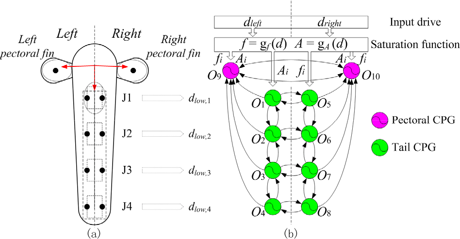
Configuration of the CPG model for the AmphiRobot-II
As illustrated in Figure 2, the CPG network for AmphiRobot-II comprises tail CPGs and pectoral CPGs. The pectoral fin on each side corresponds to a nonlinear oscillator, O9 and O10 separately, with the output signal as the control command to drive the pectoral fin. The actuated joint angle signals of the pectoral fins can be expressed as
Coupling weights between the CPG elements

3. Hydrodynamic modelling
3.1. Kinematic analysis based on the multi-link serial mechanism
The determination of an optimal locomotion gait for AmphiRobot-II present an acutely challenging problem, involving the robot's body kinematics and the hydrodynamics of the surrounding water. The intractability of the hydrodynamics of a flexible body involves various uneasily-enveloped factors, such as added mass, trailing vortex effects and leading-edge suction, etc. For the purpose of simulation, a simple physical model of AmphiRobot-II is created to test various locomotion gaits.
Figure 3a shows a simplified five-link mechanism and pectoral fins where the first link corresponds with the head attached by the first modular propelling unit and the last with the caudal fin. The world rectangular coordinate system (WRCS) XOY is established with the origin placed at the starting point of the second link. At the initial moment, the robot body is adjusted to a line while the X-axis directs towards the head with the Y-axis towards the left side of the robot. Specifically, θ
i
is the angle between the ith link and the X-axis (i= 1, 2, …, 5).

Dynamic model of the amphibious swimming robot. (a) System configuration of a five-link serial mechanism and reference frames description. (b) Pressure on the ith link. (c) Approach stream pressure on the head. (d) Friction drag. (e) Pressure on the left pectoral fin.
From Figure 3, the position of the centroid in each link can be expressed as:
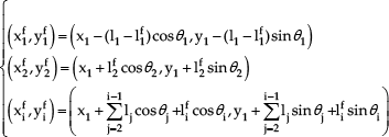
where
We can get the velocities of the ith link relative to water – i.e.,

As distinct from the links oscillating in the horizontal plane, the pectoral fins keep oscillating in the vertical plane. As shown in Figures 3 a and 3e, the centroid of the left pectoral fin can be obtained:
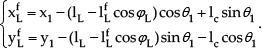
Likewise, the velocity of the pectoral fins can be formulated as below:

3.2. Lagrangian dynamic modelling
The commonly used approaches to fluid-body interaction have focused on twoaspects. The former involves a reduced Lagrangian formulation, where a fish is taken to be a rigid body with the action of the tail [22]. The latter is based on a highly simplified quasi-static lift and drag model of forces acting on the fish body and tail [23]. Morgansen et al. have extensively presented a modest model of the latter [24]. The designed modular amphibious robot can be regarded as a multi-link serial mechanism coupled with pectoral fins and represented by thin plates, which can be solved by the Lagrangian function with explicit joint angles as input variables. As a bonus offered by our robot, repeatable experiments can easily be conducted to verify the simulated swimming model in the Mathematica environment, which makes the hydrodynamics computation tractable.
For the convenience of theoretical analysis, some suppositions are made below:
The instantaneous force is out of balance in the vertical plane. Taking into account the intrinsic frequency of the oscillating joint and oscillation symmetry, the vertical movement is temporarily suspended. AmphiRobot-II mainly employs fish-like swimming, where the swivelling body device is casually disabled. To lay out a primary design scheme, the overall buoyancy counterbalances the gravity and only the forces in the horizontal direction are taken into consideration (e.g., thrust and resistance). The 3-D dynamic analysis will not be considered for the moment.
The potential energy is constant (E) according to Supposition 3. The kinetic energy of each link comprises translational kinetic energy within WRCS and the rotational kinetic energy within the centre-of-mass system. Thus, the Lagrangian function will be expressed as follows:
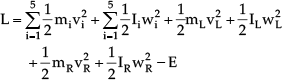
where

where F X and F Y are the compositions of the hydrodynamic forces on the X axis and Y axis, respectively. MΘ is the moment about the point (X, Y). Notice that X, Y and MΘ are the functions of time evolution – i.e., X(t), Y(t) and MΘ(t) – which are fundamentally decided by the joint actuation laws.
3.3. Hydrodynamic force approximation
The interaction of a robot swimming underwater with the fluid flow is a crucial issue that remains unresolved. The hydrodynamic aspects of swimming have been described in various models [25,26]. In many cases, some simplifications are necessary. To calculate the resultant forces, a large Reynolds number is applied and all of the forces acting on any propulsive element are due to the motion of that element in the fluid. The movement of any object through a stationary fluid causes an increase in pressure in front of the object and a decrease behind it. The different pressures on the two sides also give a net drag force to the object, counteracting the movement. Forces acting on the body from the surrounding water depend upon the speed of the body relative to the water. The movement of robot's propulsive elements through the fluid causes pressure differentials to develop on either side of the elements, resulting in drag forces in opposition to the motion. Next, each link is acted upon by three forces: pressure on the links, the approach stream pressure and friction drag.
3.3.1. Pressure on the links
While oscillating, the hydrodynamic force acting perpendicular to the surface of the ith link is the thrust for advancement (see Figure 3b), which is given by:
Many fish balance vertical forces by continually swimming, with their pectoral fins flapping and while maintaining a steady swimming speed. Thanks to the pectoral fins mounted on both sides of the head, the robot is more agile for turning or maintaining balance in the water. The propulsive forces generated by the pectoral fins in conjunction with the rear body promote the robot in moving forwards. While oscillating, the pectoral fin produces the perpendicular pressure and parallel friction drag in relation to the surface. The thickness of the pectoral fin is small and the friction drag can be ignored simply by considering the perpendicular component that contributes to propulsion (see Figure 3e). As with the moving links, the pressure on the pectoral fin is given by:
Similarly, 
3.3.2. Approach stream pressure
During swimming, the robot suffers from a resulting force which acts upon the head in opposition to the motion – i.e., the approach stream pressure (see Figure 3c). Owing to a larger cross-section of the head with small oscillation amplitudes of the rear body, the drag forces acting on the other links can be ignored, except for the head. The drag force on the head is given by:
3.3.3. Friction drag
Friction drag arises as a result of the viscosity of the fluid flow between the fish body and the boundary layer of the water (see Figure 3d). The movement of the robot's propelling units through the fluid causes friction drag parallel to the propelling units, resulting in drag forces adverse to the motion. It is empirically evaluated as 20−50% of the approach stream pressure (i.e.,
3.3.4. Composition of the hydrodynamic forces
By resolving all of the above forces in the WRCS, the components of the forces in the direction of the X-axis and the Y-axis can be rewritten as:

where
The composition of moment acting on the hinged joint point (X, Y) is given by:

Based on (7)–(9), a system of partial differential equations of X, Y, Θ, and t can be obtained:

To further solve the above equations, some initial values should be given. Suppose that the robot is at the origin at the initial moment and that the robot body maintains itself motionless in a line – i.e., X(0)=0, Y(0)=0, Θ(0)=0,
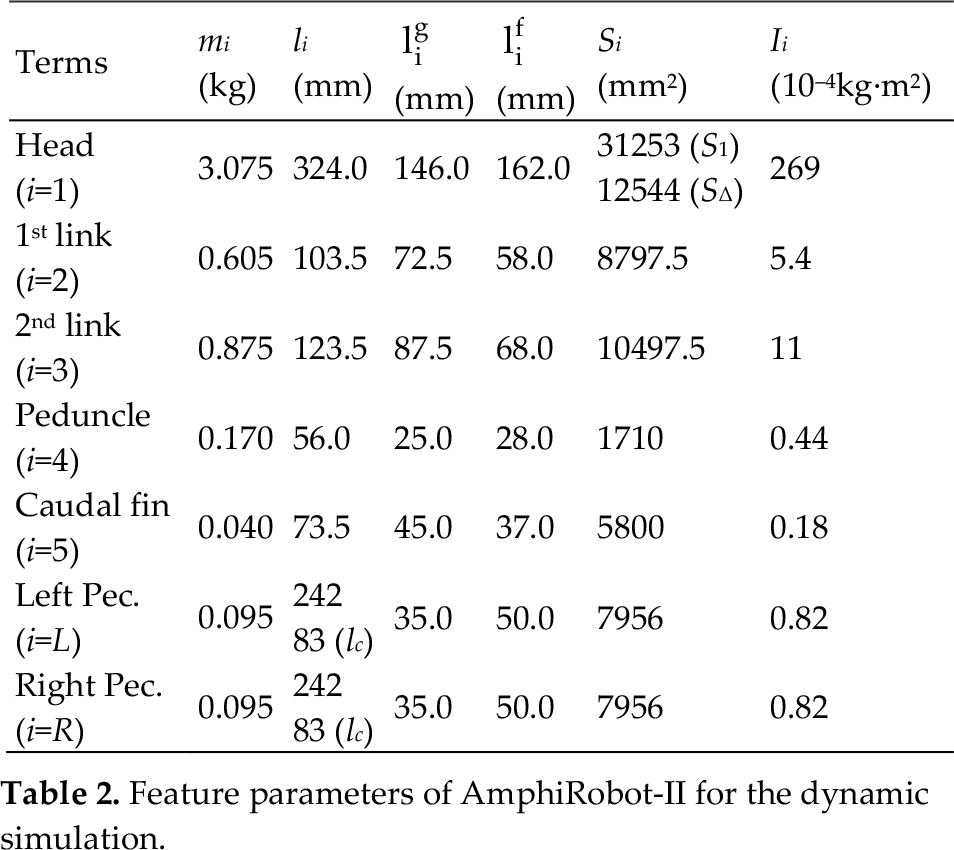
Feature parameters of AmphiRobot-II for the dynamic simulation
Notice that, in a similar fashion to the hydrodynamic modelling of fish-like lateral motions, dolphin-like dorsoventral motions can be dynamically simulated with the same kinematic analysis and hydrodynamic force approximation [28]. Hence, a comparison between fish- and dolphin-like swimming in the same robotic platform becomes available.
4. Simulations and experiments
4.1. Simulations
By assigning the same drive between the left and right sides of the model – e.g., d L =d R =3 – the corresponding oscillatory frequencies and amplitudes for moving joints can be obtained from the CPG model, which can then be imported into the Lagrangian model. Figure 4a shows the displacement of the point (X, Y), where the robot moved in the negative-direction of the X-axis. The orientation is not strictly in the negative direction, for the reason that the forces acting upon the robot are not absolutely symmetrical at the start time, as illustrated in Figures 4c and 4d. The oscillation curve of Θ in Figure 4b partly demonstrates the relative accuracy of the hydrodynamic model. The moment acting on the point (X, Y) is plotted in Figure 4e. It is a vital parameter for the servomotor selection and the maximum moment of the servomotor should satisfy the simulation result. With the simulated results, the average velocity can be estimated by:
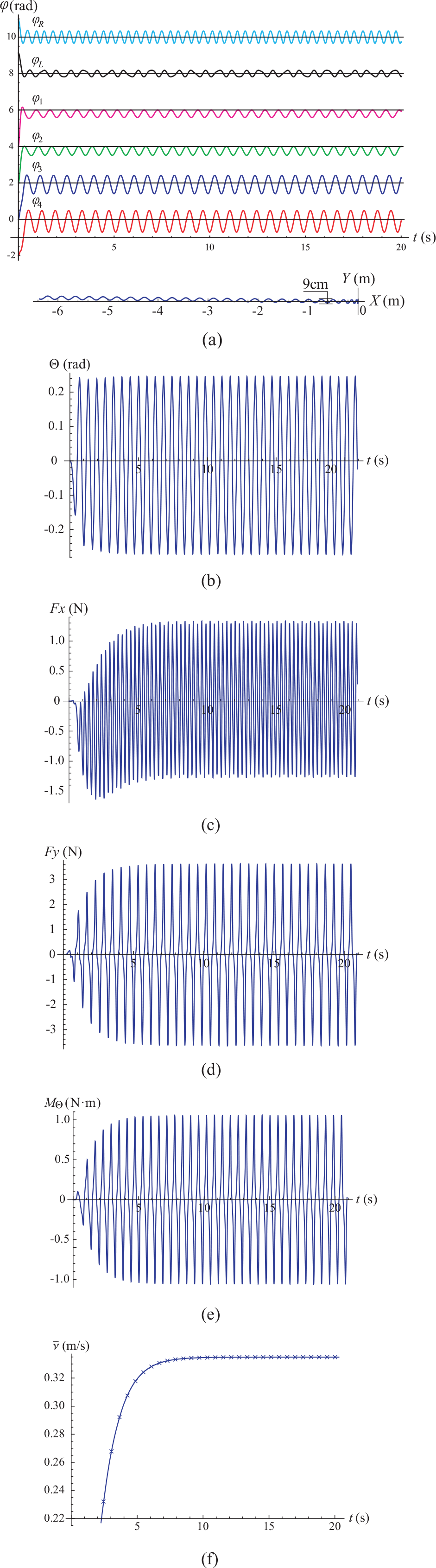
Simulated forward gait. (a) Forward swimming trajectory. (b) Oscillatory angle signal of Θ. (c) Hydrodynamic forces acting on the X-axis. (d) Hydrodynamic forces acting on the Y-axis. (e) Moment acting on (X,Y). (f) Average velocity at every period.

where t s is an arbitrary time after the simulation is steady and T is the oscillating period indirectly obtained from the oscillating frequency. The velocity curve obtained in Figure 4f indicates the motion stability after several periods, and the steady average velocity is 0.335 m/s.
Meanwhile, turning can be induced when asymmetrical drives are applied between the left and right sides of the CPG model. The robot will turn towards the side receiving the higher drive. The posterior body keeps oscillating at a common frequency in terms of synchronization, which is in vain for modulating the direction. The turning gait will mostly be credited to asymmetrical oscillation amplitudes of all the joints in the posterior body, with the side receiving higher input drive oscillating at higher amplitudes, as shown in Figure 5a. The turning motion simulation is displayed in Figure 5b at d L =1.5 and d R =3.5, and the average turning radius is around 1.15 m. Notice that the pectoral fins will oscillate in their own intrinsic frequencies due to unattained critical input drive during swimming. The differences of the oscillatory frequencies and amplitudes of the pectoral fins on both sides will also help turning and assist with propulsion. The successful simulations of forward gaits and turning gaits show the effectiveness of hydrodynamic modelling in describing yaw motions.
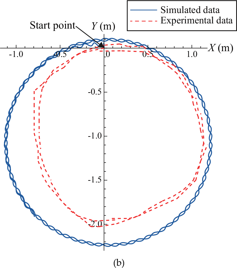
Simulated turning gait. (a) Actuated joint angle signals from the CPG model. (b) Comparison of turning trajectories.
In addition, by modulating the attack angle of the pectoral fins, the robot is able to achieve an up-and-down motion, termed ‘pitching gait’. Figure 6 shows the comparative results between simulations and experiments on the pitching gait, where the attack angle increases from 0 to 60º, with a step of 10º. The simulated data largely conforms to the experimental data over the whole range of attack angles, demonstrating the validity of hydrodynamic force analysis in relation to the pitching motions. More interestingly, Figure 7 depicts the comparison results of fish- and dolphin-like modes. The simulation demonstrates that the dolphin-like swimming precedes the fish-like mode, with a higher speed comprising a 6% increase at a maximum input drive d l =d r =5, though it is less remarkable. In particular, aquatic experiments verify this trend. The established dynamic model that is capable of fish- and dolphin-like swimming simulation further verifies the effectiveness of the whole hydrodynamic analysis when primarily involving three types of forces.

Comparison of simulated and actual pitching gait via modulating attack angle of the pectoral fins

Comparison of simulated and actual propulsive speeds between fish-like and dolphin-like modes
4.2. Experiments
The experiments were performed in a lake and the drive signals were generated through wireless communication by a human operator. By applying the same drive between the left and right sides of the CPG model, the AmphiRobot could realize forward swimming. As the same drive is increasing and is applied to both sides, the swimming distances and corresponding consuming time are measured at drives ranging from 1.0 to 4.0, with a step of 0.5. As the equal input drives cannot serve as a guarantee of actual locomotion in a straight line – the measurement has been run three times for a specific drive. The average velocity can thus be calculated.
At present, the robot is able to achieve different forward gaits in BCF mode (by oscillating only the body and/or caudal fin) or in PF mode (by oscillating only the pectoral fins), or their combination PF+BCF. Figure 8 demonstrates how the input drive affects the propulsion velocity in different forward gaits. The velocity curves partly confirm the biology-inspired concept that fish typically rely on the BCF mode for propulsion while employing the PF mode for manoeuvring and stabilization. The velocity increases with the drive and attains the maximum velocity when the input reaches the maximum acceptable drive. The experimental results generally agree with the simulated velocity curve despite the existence of small errors. This could be due to an inaccurate model, a simplified mechanical analysis and initial random parameters.
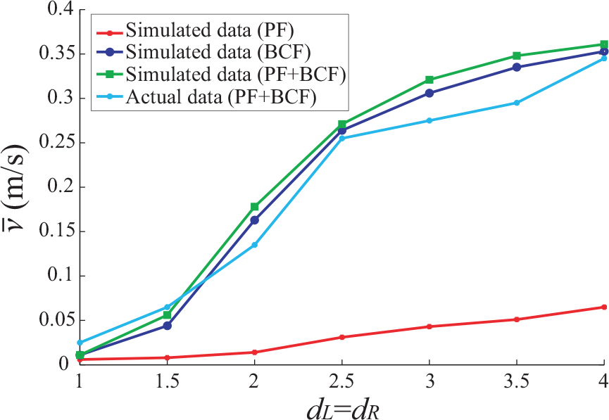
Propulsion comparison of different forward gaits
Furthermore, a series of terrestrial and aquatic locomotion gaits were successfully implemented (see Figure 9), which can significantly expand the operational field and capability of the amphibious robot. Currently, the gait transition is primarily induced by modulating the activity of the CPG, the attack angle of the mechanical pectoral fins or else the swivelling mechanism. As a quantitative case, the average turning radius shown in Figure 9d is approximately 0.95 m, which is minor in contrast with Figure 5b. This mainly owes to the larger bending of the rear body and the approach stream pressures produced by the rear body, which are ignored in the dynamic model. In particular, the experimental trajectory of the turning robot exhibits an irregular circular path. This phenomenon might be caused by the drive difference that undermines the balance of the robot body tilting to the side of the small drive.
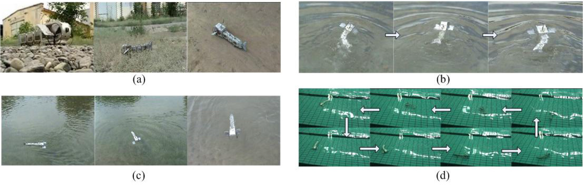
Multimodal amphibious locomotion in different environments. (a) Crawling in terrestrial environments, including stony ground, grassland and a bumpy road. (b) Gait transition between fish- and dolphin-like swimming. (c) Multiple swimming gaits, including backward swimming, turning on the spot and braking. (d) Turning underwater.
5. Conclusions
This paper presents the modelling and control issues of an amphibious swimming robot capable of multimodal motions. To generate robust gait control for steady swimming, a CPG-based control law was designed to produce the joint angle signals of the propelling units. A hydrodynamic model based on a Lagrangian formulation has been proposed for underwater locomotion. By introducing the CPG-based control into the hydrodynamic solution, multiple gaits could be numerically estimated. Comparative results have been given to show the effectiveness of the formed dynamic model combined with the CPG-based control model.
Further research will focus on mechanical and gait optimization for improved amphibious performance. Furthermore, sensory feedback information will be integrated into the CPGs to improve amphibious locomotor performance.
Footnotes
6. Acknowledgements
This work was supported by the National Natural Science Foundation of China (60775053, 61075102) and, in part, by the Beijing Natural Science Foundation (4102063, 4122084).