
Abstract
This paper presents autonomous control for indoor small helicopter X.R.B. In case of natural disaster like earthquake, a MAV (Micro Air Vehicle) which can fly autonomously will be very effective for surveying the site and environment in dangerous area or narrow space, where human cannot access safely. In addition, it will be helpful to prevent secondary disaster. This paper describes vision based autonomous hovering control, guidance control for X.R.B by model reference sliding mode control.
Keywords
Introduction
Humans are fascinated by levitation. The reason is probably that the world we are living in is three-dimensional. However, human beings live and move mainly in two dimensions. It seems that humans have a very strong drive to overcome their biological limits. This means, they build machines that enable them to move in three-dimensional space, e.g., airplanes. These machines are not restricted to operating in two dimensions. A small machine which can fly autonomously is appropriate for investigation of the atmosphere under environments where nobody can exist, or regions where nuclear pollution and biohazard are generated, or other critical situations. Because no matter how complicated the geographical feature is, it won't become a trouble if it flies in the air. What's more, it is possible to use it even in a considerably hazardous region. Not only can it act along, but also can be coordinated to work as a group with tens or hundreds of robots to complete a wide-ranging investigation. A micro size flying device (Micro Air Vehicle: MAV) refers to a new class of aircraft whose target dimensions are less than 15 cm (6 in) in any one dimension. In the future, even insect size vehicles are envisioned. The Defense Advanced Research Projects Agency (DARPA) is the U.S. agency at the forefront of MAV development[1][2][3].
MAV's development started for the use as an uninhabited aircraft for the search operation in a short distance in the arena of warfare. For other purposes, MAV can be used for surveying polluted area by NBC (Nucleus, Biology, and Chemistry) weapons, radio relay in place where communication is difficult, or rescue operation such as finding landing point when the aircraft pilot escapes.
Obviously, to perform such tasks, MAV must be capable of flying autonomously instead of by radio control. However, there are a lot of technical problems, especially installing power supply, communication apparatus and sensors is very difficult. In our research, we have used Micro Flying Robot (μFR) which is about 12.3 grams in total as our controlled object, and achieved vision based autonomous hovering control[4]. The photo of μFR is shown in Fig.1. However, because μFR is still being developed, it is difficult to be used in experiment. So we also perform experiment with X.R.B, a wireless small helicopter which is made by Hirobo Corporation. The photo of X.R.B is shown in Fig.2.

Photo of Micro Flying Robot (μFR)
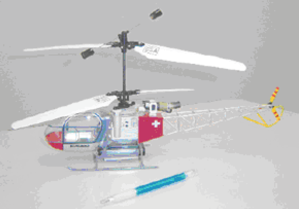
Photo of X.R.B
Now, a UAV that achieves autonomous flight almost can observe each state of the flight body by installing GPS, gyro sensor, and acceleration sensor, etc. But in case of μFR and X.R.B, because the payload is limited, it is difficult to install GPS and such other sensors. Then, in this research, we measure the three-dimensional coordinates of the flight body by using one CCD camera to recognize a square marker sticking to the bottom of the flyer whose size is already-known (marker position detection method)[5]. If a flyer flies in the range of the camera, we can measure the relative position of it so it is possible to achieve autonomous control. However, the control becomes impossible while the flyer starts to depart from this area. To expand the range of the observation, we use a computer controlled camera platform to track the flyer as it moves. As a method of controlling a small uninhabited helicopter, we usually separate the control system into three loops – position control loop, velocity control loop and attitude control loop[6][7]. But such a method cannot be adopted by this research because that we can't observe attitude and speed of our controlled object by CCD camera only. Thus, we propose a simple control system loop which only has a position feedback. This paper describes the modeling and model reference sliding mode control(MRSMC) of X.R.B.
The lift and hovering capability typical of a helicopter come at the cost of reduced dynamic stability. The helicopter flight controller is therefore a key element of our system. After evaluating several other models, a helicopter with a counter rotating dual rotor configuration was chosen for this study. The counter rotating configuration is well known for delivering high efficiency as well as achieving excellent stability thanks to the direct compensation of the torque between the two rotors. The model we have selected uses a conventional fully controlled lower rotor, and an upper rotor fitted with a 41 degree stabilizer bar. The stabilizer bar exploits gyroscopic forces in order to counteract sudden changes in shaft inclination. This results in improved stability, but of course this comes at the cost of a reduced response to control commands. Testing by human pilots showed the model to be more stable and easier to fly than conventional single rotor helicopters.
Testing also established that the model can be flown with a payload of about 50g for about 10 minutes; we deem this sufficient to achieve the project's aims. The specifications of X.R.B are shown in Table 1.
Spac. Of X.R.B

Spac. Of X.R.B
The image of experimental setup used in this research is shown in Fig.3, and the photo is shown in Fig.4. A USB2.0 camera (50frames/s) is used to recognize the marker attached to the flyer. The image taken is sent to the image processing server. In the image processing server, three dimensional position of the flight body is calculated. The result of the calculation is transmitted to the control server. The OS of processing and control servers are windows operating system and programs are written in Microsoft VC++ 6.0.

Configuration of Experimental setup
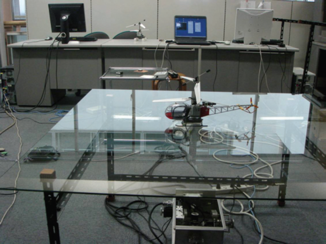
Photo of Experimental setup
A Giga network is used to make the transmission rate on time. A timer board is used for accurate timing of the image acquisition. The controller processes the location information and transmits control instructions to X.R.B through radio communication. A USB Proportional Controller (Propo) can also be used to control the flyer manually.
In general, it is possible to measure three dimensional coordinates only when it is possible to take two or more images of an object from different positions at the same time with multiple cameras. However, it is difficult for the micro flyer to use such technique because of the long data processing time. So we used one CCD camera to measure three-dimensional coordinates of the flyer by recognizing a square marker[4][5].
However, the weakness of using such technique is that the observable flight area is narrow. It is no problem if the flyer is hovering stably, but the problem occurs when the flyer encounters large turbulence or we attempt wide-ranging flight. To solve this problem, various proposals were examined, such as the use of a wide-angle lens or a multi camera system. Ultimately we decided to use a computer-controlled camera platform(Fig.5) to track the flyer as it moves to expand the range of the observation and thus the range of flight.

CCD camera and Computer controlled camera platform
The computer controlled camera platform used in this research uses a precise rotation platform to rotate pan, and tilt. The maximum turn speed is 20°/s. The platform connects with the computer by USB. Moreover, a potentiometer is installed to measure the angle of the stage. However, the platform driver cannot continuously receive instructions while the platform rotates. Therefore, it is not possible to rotate the camera continuously to track the movement of the flyer. Rather than attempt to move the camera every time sample, we propose the following technique: when the flyer departs 5 degree from the centerline of the camera, the camera will rotate 5 degree. The block diagram of this active camera system is shown in Fig.6. When a fixed camera is used, the range of view in the X and Y directions is about 60cm × 60cm when the flyer is about 1m away from the camera. When camera platform is used, the recognition area is expanded to be 140cmx140cm which is 4 times larger than before.

Block diagram of camera system
Fig.7 shows the camera coordinate system which is used in this research. The origin is defined as the position of X.R.B when the autonomous flights control start.

Coordinate system
X.R.B is of counter rotating dual rotor type, and the each degree of freedom is controlled by adjusting the rotational speed of the upper and lower propeller and the inclination of the main body. Therefore the motion is coupled. However, because it is not easy to model such a MIMO system, in this research we disregard the coupled motion and consider each degree of freedom as an independent SISO system and design the control system accordingly. Because the models of the Z(height) direction and the yaw motion can be thought to be stable systems, we adopt PID control for which the performance can be improved by tuning even when there is no model. But for the X and Y directions, the models are unstable and it is not easy to find the gain for a PID controller which can stabilize the system by tuning. So first modeling is carried out and a model-based MRSMC controller is designed.
Because the X and Y direction are almost symmetrical structurally, the mathematical model of the X direction obtained by system identification can also be applied to the Y direction.
At first, we assume the transfer function from the input of Propo to attitude as follows:

However, because the attitude of the airframe cannot be measured, this expression cannot be used directly. Moreover, the transfer function from the attitude angle to displacement can be thought as follows:

From equation 1 and 2, we can get the transfer function from Propo to displacement as follows:

And then the input and output data obtained from experiment is supplied to the system identification tool of Matlab to identify unknown parameter a 0 , a 1 , a 2 and k. Then the state equation is obtained as Eq.(4).
The frequency response of the mathematics model is shown in Fig.8. To verify the accuracy of the identified model, we made a time history response analysis, and the result is shown in Fig.9.

Frequency response of identified model
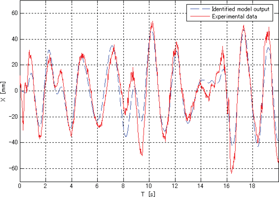
Cross validation result

The real model of helicopter can be thought as nonlinear and strongly coupled. Hence it is important that the designed controller is robust not only with respect to stability, but also with respect to performance. In this research, we designed model reference sliding mode controller(MRSMC) for X and Y direction of X.R.B.
Model reference control(MRC) has since its inception, found application in a wide range of applications from the control of simple mechanical structures to the more complex robotic manipulators. Servo systems are usually required to provide accurate control both in terms of disturbance rejection and command response. A convenient way to give specifications for a servo system is to use a MRC structure. The advantage of this configuration is that the servo problem and the regulator problem are separated. In MRC system the desired response to a command signal is specified by a reference model which provides the reference signals to the feedback loop. A block diagram of MRC is shown in Fig. 10. Then, the task of the feedback controller is just to drive the error between the output of the process and output of the reference model to zero. In general, the feedback controller should be designed so that the system becomes insensitive to disturbances and plant uncertainties. For this purpose, SMC is a most attractive method due to its robustness properties[8][9].

Block diagram of MRC
There are many ways to generate the reference signals. In state space design, it is convenient to specify a reference model whose states correspond directly to the states of identified model[10][11], i.e.,
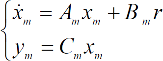
Where r is the command input. By denoting C
m
= C, e=x-x
m
, the error dynamics of the feedback control loop is obtained by subtracting Eq.(4) from Eq.(5), i.e.

Assumed this system satisfies the following model matching condition.

Then,

By using B+, the Moore-Penrose Matrix Inverse of B, K
1
can be obtained as

Because output y
m
is settled to r if the DC gain is adjusted to 1, B
m
can be decided so that steady-state value of the reference model may become 1. Because When time approximate to infinity, DC gain of reference model convergent to 1, so K2 = (−C
m
A
m
−1B)−1 can be obtained by Eq.(5) and Eq.(7). Then B
m
can be calculate by

A
m
is decided by tuning, i.e.

The step response and ramp response are shown in Fig.11 and Fig.12.
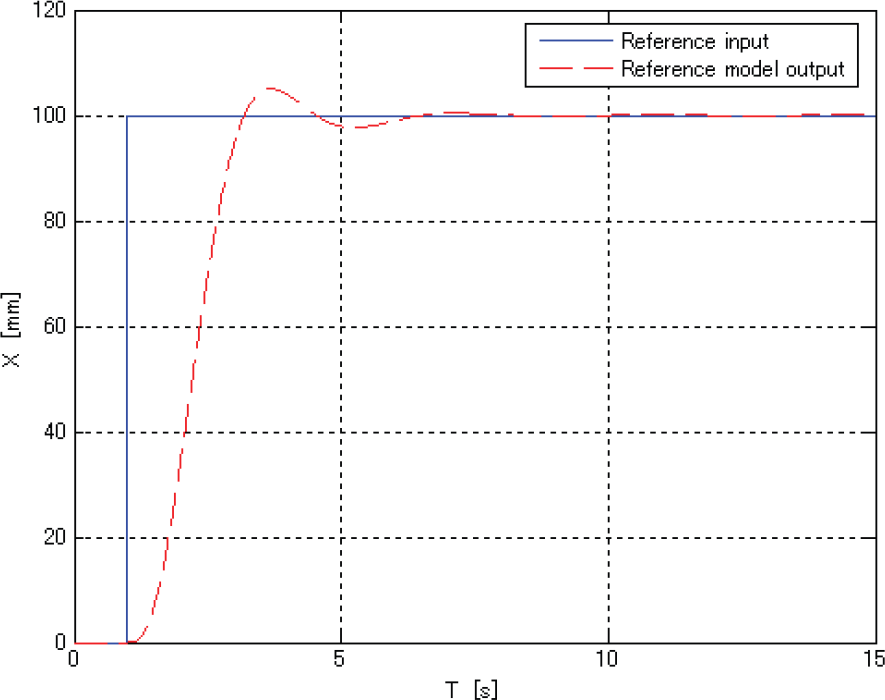
Step response of reference model
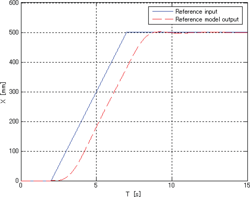
Ramp response of reference model
For tracking control, an integral action can be introduced into the SMC to improve the tracking performance[9]. Consider that the control goal is to make the tracking error e
y
be 0, and consequently a new state ε which integrates the error e
y
is introduced, i.e,.

And the augmented system is

For the error system, the switching function 

When the plant is restricted on the sliding surface, σ = σ = 0 and equivalent input u
l
= u is obtained by Eq.(16).

When u is substituted for Eq.(13), Eq.(17) is derived.

It is known that the system of Eq.(17) becomes stable by stabilizing zeros. To stabilize it, the optimal control method is adopted and feedback gain F is selected as hyper plane S. P is the solution of the Riccati equation, and S is satisfied with SB
s
> 0.


SMC is distinguished by the nonlinear term,

where K is a switching amplitude and f(σ) is a switching function. The high-gain switching feedback is generated by the polarity of the switching function, so a sign function can basically be used. The sign function, however, is too critical for practical use, so some methods are contrived to avoid chattering. In this research, we selected a smoothing function,

where δ is the weight of smoothing. Around the switching line, the smoothing function can make the gain high while sustaining sufficient robustness. Several methods concerned with SMC have been proposed. This method is called the eventual sliding mode.
Because only output data can be observed, so a Kalman filter is designed to estimate state variables which cannot be observed. The block diagram of MRSMC is shown in Fig.13. And Fig.14 shows the simulation result of MRSMC by step signal.
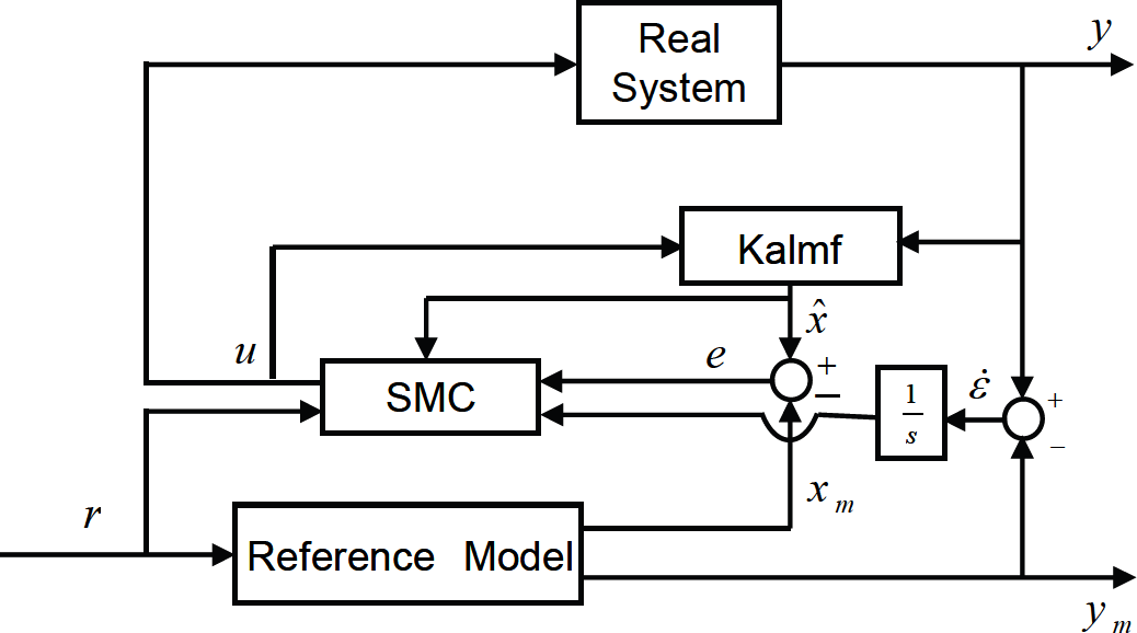
Block diagram of MRSMC

Simulation result of MRSMC
To evaluate the designed controller, the following typical experiments are carried out:
Hovering control Experiment
The feature of the helicopter is that it has hovering ability. So at first, autonomous hovering control experiment is carried out.
The step of this experiment is: use a USB Propo to control it takeoff manually, and when it is under a stable flight condition, we switch it to autonomous hovering control mode.
The experimental result is shown in Fig.15, and the result of X and Y 2-dimension plane is shown in Fig.16. From the experimental results of Fig.15 and Fig.16, we can see that the fluctuation of the direction X and Y is almost settled within the range of −100mm to +100mm from control starting point. And the range of the yawing has been restrained in −5° to +5° too. A preferable result has been obtained.

Experimential result of hovring control

Experimential result of hovring control
At first, let X.R.B fly with autonomous hovering control mode as above experiment. Then step reference input is offered to the reference model. The value of the step reference signal is 400mm. The experimental result is shown in Fig.17.

Experimential result by step reference
From Fig.17, we can see there is no steady-state error and little over shot, so good follow performance was obtained.
The step of this experiment is: at first let X.R.B fly with autonomous hovering control mode, and the start point is defined as the center of a circle trajectory, then X.R.B move to the circle trajectory by a 400mm ramp reference signal input of X direction. After 4 seconds hovering, X.R.B continued the autonomous guidance flight by the circle trajectory which diameter is 800mm. At last, it returns to the center of the circle trajectory.
The experimental result is shown in Fig.18, and the result of X and Y 2-dimension plane is shown in Fig.19. From the experimental result, we can see there is a little delay from the reference trajectory, so we obtained good follow performance by the designed controller.
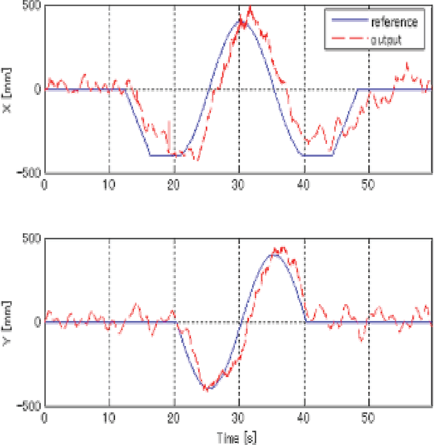
Experimential result by circle trajectory
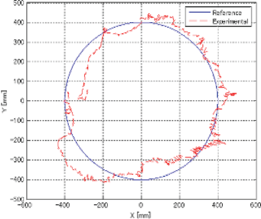
Experimential result by circle trajectory
In this research, we have proposed autonomous flight experiment setup which uses 3D vision system to observe the position of X.R.B. The mathematical model of motion in the X and Y direction is obtained by system identification. PID controllers and model-based model reference sliding mode controller are designed. The autonomous hovering control and guidance control are realized in flight experiment. Our future work will focus on obstacle avoidance and swarm control.