
Abstract
A 4-UPS-UPU 5-Degrees of Freedom PCMM(Parallel coordinate measuring machine), which can achieve three translation degrees of freedom and two rotational degrees of freedom, is presented in this paper. The inverse position model of the 4-UPS-UPU PCMM is established. The Jacobian matrix, and the expressions of velocity and acceleration are deduced. Furthermore, a numerical analysis of the inverse solutions of the position, velocity and acceleration are carried out. The results are confirmed by a virtual simulation of the 4-UPS-UPU PCMM prototype. This research has laid a solid foundation for the motion control and movement performance analysis of the 4-UPS-UPU PCMM.
Keywords
1. Introduction
The PCMM, as a type of new-structure measuring machine tool, has been utilized for many practical applications[1], such as machinery manufacturing, automation, aerospace, assembling robots, etc. Compared with the traditional CMM, the PCMM has the advantages of good kinematic/dynamic performance, high stiffness, tight construction and no accumulated precision errors.
In recent years, most of the PCMMs have been developed based on a 3-DOF parallel mechanism and a 6-DOF Stewart platform [2–6]. However, the 3-DOF PCMMs cannot measure points on complex surfaces. Since the 6-DOF PCMMs must have six motors, the manufacturing cost of 6-DOF PCMMs is high. Due to the nature of its design, the general 5-DOF PCMMs with five motors can meet the measuring requirement. Therefore, the PCMM with 5-DOF has received more and more attention from various industries and institutions. The kinematics analysis of PCMM provides an important foundation for the following research, including knowledge on motion control, movement performance analysis, working space, control algorithms, accuracy analysis, and so forth.
This paper focuses on the kinematics analysis of 4-UPS-UPU PCMM. The inverse position model of 4-UPS-UPU PCMM is constructed, and the Jacobian matrix, and the expressions of velocity and acceleration are deduced. Based on the kinematics model mentioned above, a numerical analysis of 4-UPS-UPU PCMM is carried out and verified by an ADAMS simulation.
2. Description of 4-UPS-UPU PCMM
The 4-UPS-UPU PCMM is shown in Figure 1; it consists of a stationary platform, a moving platform, four UPS (Universal joint-Prismatic pair- Spherical joint) actuating limbs, a UPU (universal joints-prismatic pairs- universal joints) actuating limb and a working head. The moving platform and the stationary platform are connected by four UPS actuating limbs and a UPU actuating limb. The probe is attached to the centre of the working head. When varying the length of the five actuating limbs, the probe was able to perform five DOF movements. Thus, the aim of measuring a complicated surface can be achieved. The 4-UPS-UPU PCMM has some characteristics such as an easy inverse and forward solution, small movement inertia, nimble position and pose of its moving platform, et al.
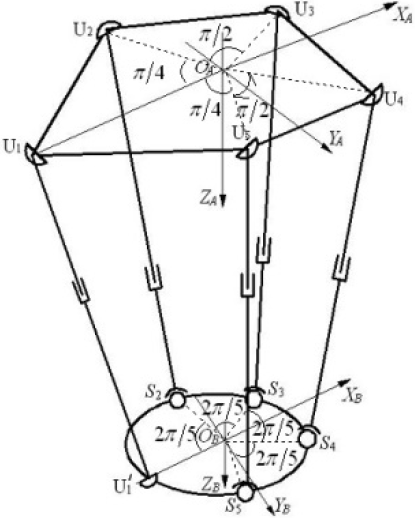
Mechanism diagram of PCMM.
3. Kinematics analysis of 4-UPS-UPU PCMM
3.1. Inverse position analysis
As shown in Fig. 1, we establish the reference frame {A} on the stationary platform and the moving frame {B} on the moving platform.
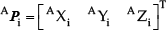
Given the position and orientation parameters
The five universal joints of the stationary platform are arranged as shown in Fig. 1. One universal joint U1 is along the reverse X-axis of {A} and its coordinate value is W. The rest of the four universal joints are arranged uniformly, the radius is denoted as

The four spherical joints and one universal joint of the moving platform are arranged uniformly. The universal joint is along the reverse X-axis of {B}. The radius is denoted as

The coordinate of the five joints
Then the length vectors of the five actuated limbs with respect to {A} is given by

where
When

Thus the length of the five actuating limbs is given by
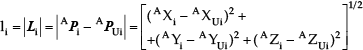
Where

Based on the inverse solution equation (6), the position and orientation of the working head on the moving platform planned in the working space of the PCMM can be transformed to the length of the actuated limb in the joint space. In this way, the control of the position and orientation of the working head when measuring is carried out.
3.2. Inverse velocity solution analysis
As shown in Fig. 2,

Velocity diagram of the mechanism.
Then the equation is obtained as follows

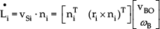
For all the five actuated limbs, the relationship between the velocity of the moving platform and the velocity of the actuated limbs is given by

Where

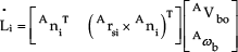
The Jacobian matrix
The angular velocity of the moving platform

Where
Because the rotation of the moving platform around its center axis is constrained by the construction of the mechanism,

Put equation (12) into equation (8), So the Jacobian matrix

Where

The Jacobian matrix
3.3. Inverse acceleration solution analysis
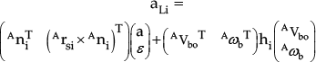
Assuming two vectors are
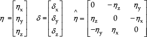


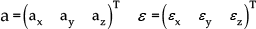
When presuming a is the linear acceleration of the moving platform, ε is the angular acceleration of the moving platform, and
From the equation

Where
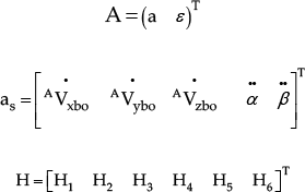
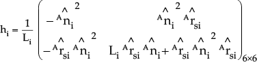
The Hessian matrix

From the equation
According to equation (17), If
4. Kinematics verification of 4-UPS-UPU PCMM
The structural parameters of the 4-UPS-UPU are illustrated as follows. The distance between the first universal joint and the centre point on the stationary platform is 780mm, the distribution radius of the other universal joints on the stationary platform is 720mm. The distribution radius of the spherical joints on the moving platform is 200mm.
The motion of the centre of the moving platform of the 4-UPS-UPU PCMM is described as

The numerical analysis of the length, velocity and acceleration of the actuating limbs for 4-UPS-UPU PCMM by using inverse kinematics model, are shown in Figure 3, Figure 5 and Figure 7. According to Figure 3, Figure 5 and Figure 7, the length, velocity and acceleration of the actuating limbs vary greatly with the different poses of the moving platform and the length value of the actuating limbs is between 950mm and 1200mm, the velocity value of the actuating limbs is from −150mm/s mm to 150mm/s, the acceleration value of actuating limbs is between −250mm/s2 mm and 350mm/s2. The inverse solutions of the position, velocity and acceleration obtained by the ADAMS simulation are shown in Figure 4, Figure 6 and Figure 8. As shown in Figure 3 to Figure 8, the inverse solutions obtained by numerical calculation and the ADAMS simulation for 4-UPS-UPU PCMM are in basic agreement.
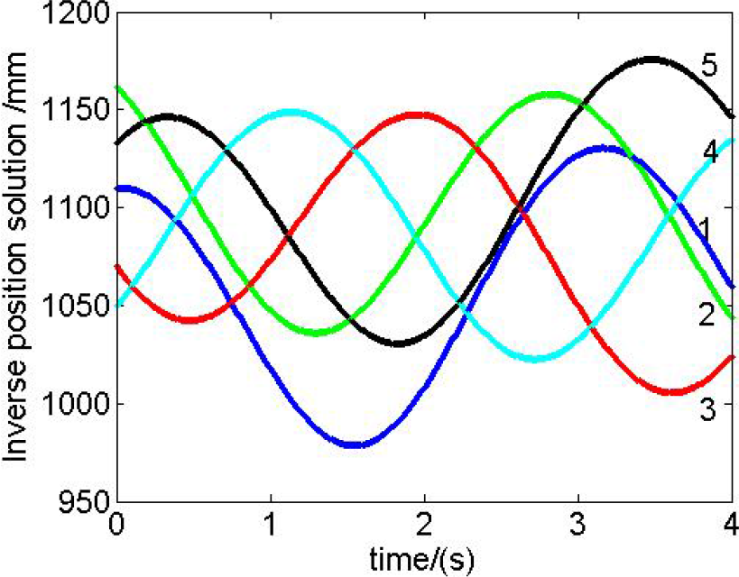
Inverse position solution by numerical calculation

Inverse position solution by ADAMS
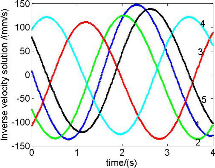
Inverse velocity solution by numerical calculation

Inverse velocity solution by ADAMS

Inverse acceleration solution by numerical calculation

Inverse acceleration solution by ADAMS
5. Conclusion
The equation for the inverse solution of position, and the expressions of velocity and acceleration for 4-UPS-UPU PCMM are deduced. The kinematics analysis of position, velocity and acceleration for 4-UPS-UPU PCMM are realized by numerical calculation. The calculation results are verified by virtual simulation on the ADAMS software. The research can provide an important theoretical base for the controlling and optimization design of these parallel mechanisms.
Footnotes
6. Acknowledgments
This research is supported by the National Natural Science Foundation of China (grant no. 51005138), Shandong Young Scientists Award Fund (grant no. BS2012ZZ008), the Natural Science Foundation of Shandong Education Department of China (grant no. J09LD54), the Science Foundation of SUST (grant no. 2011KYJQ102) and the graduate innovation foundation of SUST (grant no. YCA120329).