
Abstract
Abstract This paper presents a bio-mimetic approach to design and simulate a tortoise-like virtual robot. This study takes a multidisciplinary approach: from in vivo and in vitro experiments on animals, data are collected and used to design, control and simulate a bio-mimetic virtual robot using MD ADAMS platform. From the in vitro experiments, the geometrical and inertial properties of body limbs are measured, and a model of tortoise kinematics is derived. From the in vivo experiments the contact forces between each limb and the ground are measured. The contributions of hind and forelimbs in the generation of propelling and braking forces are studied. The motion of the joints between limb segments are recorded and used to solve the inverse kinematics problem. A virtual model of a tortoise-like robot is built; it is a linkage of 15 rigid bodies articulated by 22 degrees of freedom. This model is referred to as TATOR II. It has the inertial and geometrical properties measured during the in vitro experiments. TATOR II motion is achieved using a Proportional-Derivative controller copying the joint angle trajectories calculated from the in vivo experiments.
1. Introduction
Developing robots inspired by biological systems has been actively studied by researchers for many years. There are many successful examples of bio-inspired robots, such as robotic fish [1], robotic snake [2], robotic salamander [3] and robotic turtle [4]. However, to date, the agility, speed and robustness of a simple animal exceed by far those of the most advanced robot. The first successful bio-mimetic running robots were Sprawlita [5], [6], [7] and Rhex [8], [9]. These hexapods were fast (over one bodylength/second), could easily deal with rough terrain and were able to traverse hip-height obstacles at speed. These systems used simple open-loop controllers, and relied on the passive mechanical properties of integrated visco-elastic components for stability [5], [8], [10].
In this work, it is expected that by studying the locomotion of living animals, interesting parameters can be found and used to build mobile robots; these parameters are invariant from one species to another. The present study was carried out in a collaboration between the Institut des Systemes Intelligents et de Robotique (ISIR) and the UMR 7179 of the Museum National d'Histoire Naturelle MNHN. Two animals were studied: the European hedgehog [11] and the Hermann tortoise [12]. Two virtual models were built and simulated using the ADAMS/view platform:
The first is for the hedgehog. It is bi-dimensional and does not take into consideration the movements of the dorsal vertebrae. The second is for the Hermann tortoise. It is Three-dimensional and is controlled from measuring the motion of walking animals filmed in frontal and dorsal planes during two different locomotion cycles. This model is referred to as TATOR I.
In this study, new and more precise methods for creating and simulating a bio-mimetic virtual quadruped are presented, and a new model for the tortoise is built and simulated. The reasons behind the choice of tortoise for inspiration are:
It is a hybrid animal able of operating in both terrestrial and aquatic environments. It has a rigid skeleton attached to the shell. The head and the tail make little contribution to locomotion forces [13]. As a result, the locomotion relies on the proper movements of limbs. The dimensions of the limb segments are consistent with the field of view of the X-ray machine available in the MNHN laboratory.
The major improvements in the design are:
The accuracy and precision of measuring the inertial and geometrical properties of the limb segments are improved. In fact, in this study a 3D laser scanner is used to digitalize the body limbs, while a McroScribe was used in the previous studies. A more realistic model of tortoise kinematics is derived and used to design the virtual model. The contact forces between each limb and the ground are measured. No force measurements were carried out in previous studies. The motion tracking is improved by attaching metallic markers to the shell, filming synchronously the animals' motion in the dorsal and frontal planes, and improving the quality of X-ray films. A method to solve the inverse kinematics problem is presented and used.
This work has multidisciplinary applications:
For biologists: the virtual model is parameterized; one can easily vary any parameter such as the mass, the length of any limb segment, the nature of the joints or the directions of their axes. It can be used as a tool to study the evolution of tortoises by varying a given parameter and investigating the effect on the speed and stability of the virtual model. It can also be used to find synergies between different parameters in the system. For robotists: building a virtual model provides a controlled environment in which the effect of physical property modifications on gait performance can be studied, without the constraints of time and budget involved in experimental work.
The remainder of this paper is organized as follows: in section II, the experiments carried out on three adult subjects are described; in section III, the virtual robot TATOR II is presented. It is followed by conclusions in section IV highlighting the contributions and the future perspectives. Figure-1 gives a basic summary of the study.

Basic summary of the study
2. Experimental equipment and methods
Three adult Geochelone graeca are studied. Two subjects are alive (subject I and subject II) and The third (subject III) is dead for natural reasons. Subject I and subject III have approximately the same inertial and dimensional properties. The masses of the studied animals and the dimensions of their shells are given in Table-1.
Masses of studied subjects and dimensions of their shells

2.1 The in vivo experiments
These experiments are carried out on subject I and subject II to:
Record the Cartesian trajectories of the joint centres and those of the nine metallic markers attached to the shell. Measure the contact forces between each limb and the ground.
Figure-2 shows the experimental setup used during the in vivo experiments. It is composed of a video camera filming at a rate of 25 frames per second, an X-ray generator, a brightness amplifier, a digital camera filming at 50 frames per second and four piezoelectric force sensors.

Experimental setup used to record the motion of the studied subjects in the dorsal and frontal planes, and measure the legs/ground interaction forces. It is composed of: a- Digital camera, b- Video camera, c- X-ray generator and d- Piezoelectric force sensor.
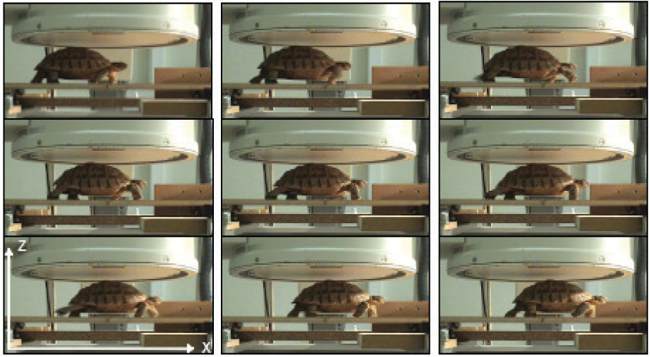
The motion of subject I is captured in the dorsal plane using X-rays films (see Figure-3) and in the lateral plane using a video camera.

Equally spaced X-ray video frames of subject I in motion filmed in the dorsal plane.
The contact limb/ground is supposed punctual. Four piezoelectric sensors are mounted under four plates of wood as shown in Figure-2. Each sensor measures the three components of a force vector. Three sensors are activated simultaneously (sensor 1, 2 and 3 in Figure-2). Many trials are carried out on subject I in motion. Figure-4 shows the recordings of sensor 3 for a given trial. One can see that the amplitude of noise is important at t=1s, this is due to the vibrations of the experimental setup when the tortoise is first put on the bench. Three quantities are measured:
The three components of the ground-reaction force on subject I left forelimb. The sum of each of the three components of the ground reaction forces on subject I left limbs. The three components of the ground reaction-force on subject I left hindlimb.

Recordings of sensor 3 for a given trial on subject I in motion
The ground reaction forces on the right fore and hind limbs are measured by sensors 1 and 2. During all the experimental trials, the force measurements show that both living subjects use:
The hind limbs to generate propelling forces. The forelimbs to generate braking forces.
The virtual model should copy the motion of subject I. The joint angles should be computed from the in vivo experiments by solving the inverse kinematics problem for a hind and a fore limb during a locomotion cycle. To solve this problem, the lengths of the segments of subject I's limbs and the Cartesian trajectories of the joints should be measured. Nevertheless, the shell-femur and shell-scapula articulations are difficult to track from the X-ray films, and are invisible in the video films. An experimental method is used to overcome these limitations and to measure the lengths of the limbs, especially the internal ones.
Subject I is placed in a static position inside a calibrated cube. Many X-ray frames are grabbed along different angles of the cube rotating at a constant speed (Figure-5).

The experimental setup used to measure the lengths of limbs and to determine the relative positions of the shell-scapula and shell-femur centres of articulation toward the markers attached on the tortoise shell
Each point of view is calibrated from the known box [14]. The relative positions of the joint centres and the metallic markers are calculated toward a frame attached to the cube using a classic triangulation algorithm. Then, the relative positions of the shell-scapula and shell-femur joints' centres are calculated toward the metallic markers attached to the shell. The Cartesian trajectories of these joints are obtained from those of the metallic markers. Each limb segment length is calculated as the distance between two consecutive articulations. Using the force measurements, the X-ray and video films, the frames corresponding to a gait cycle (stance and swing) of the right hind- and forelimbs are isolated. Then an acquisition of special points' Cartesian trajectories is done using a software developed using MATLAB. An automatic acquisition of the joints' Cartesian trajectories is not possible because of the quality of the X-ray films and the use of a video camera to film the motion of the animal in the lateral plane. From the X-ray films, two coordinates of a given point are measured (x and y in the frame defined in Figure-2) and two coordinates (x and z) are measured from the video films, x is a common coordinate, the point is defined by its three coordinates. A classical method to solve the inverse kinematics is not possible due to the important errors in the joints' Cartesian trajectories [15][16]. The inverse kinematics problem will be dealt with in detail later in this paper.
Result I: the in vivo experiments show that both living subjects use the hind-limbs to generate propelling forces and the forelimbs to generate braking forces.
2.2 The in vitro experiments
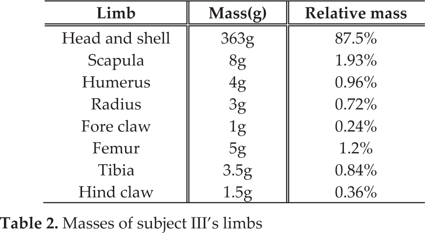
These experiments are carried out on subject III to measure its inertial properties and to model its kinematics. Before dissection, 15 markers are attached to subject III's shell and its weight is measured. The shell and the markers are digitalized; this configuration is referred to hereinafter as reference configuration. Subject III is then dissected and the weights of body limbs' segments are measured. The limbs weights include those of the muscles and the skin. Table-2 gives these quantities.
Masses of subject III's limbs
The lengths of limb segments are measured. Table-3 gives these lengths, those of subject I and the percentage of difference.
Lenghts of subjects I and III's limbs

The shell is then reconstructed using a 3D mechanical CAD program, from which the inertia matrix and the position of the centre of mass are computed. It is difficult to use this approach to calculate the inertia matrix of the other limb segments because of their complex geometry and small weight; an appropriate approximation from previous studies [11] is used. Using special chemical solutions, the muscles and the skin are removed while the ligaments are kept undamaged. The markers and the centres of the shell-scapulae and shell-femurs' joints are digitalized using a MicroScribe, this configuration is referred to hereinafter as current configuration. To determine the relative position of these points toward the centre of mass, a rotation matrix is computed using the coordinates of the markers on the shell in the reference configuration and the current configuration [17]. With the help of MNHN specialists, a functional diagram of the tortoise kinematics is drawn (Figure-6).

Functional diagram of the tortoise kinematics. 1-Head, 2-Scapula, 3-Humerus, 4-Radius, 5-Fore claw, 6-Femur, 7-Tibia, 8-Hind claw and 9-Schell
Two kinds of joints are present: spherical and revolute joints. Each spherical joint is replaced by a kinematic equivalent compound consisting of three revolute joints that have concurrent and orthogonal axes. To define the axis of revolution of the revolute joint between two bones i and i+1, the following steps are performed:
The bones of the limbs are digitalized using a 3D scanner. Coloured markers are drawn on each bone. The number of markers is greater than five (Figure-7). The bones are weighted and reconstructed using the 3D mechanical CAD program (Figure-8). The position of the markers are then defined toward two relative frames centred in the centres of mass of bones i and i+1 respectively. The axes of these frames coincide with those of the principal axes of inertia of bones i and i+1 respectively. The bone i is held in a static position and the bone i+1 is animated toward it via the revolute joint. The trajectories of the markers on bone i+1 are recorded. Each point of the bone i+1 describes a curve, these curves are in parallel planes, the common perpendicular to these planes is the revolute joint's axis. From the coordinates of the coloured markers on the bone i, a rotation matrix is calculated and used to define the position of the revolute joint's axis of revolution toward the centre of mass of bone i and i+1.
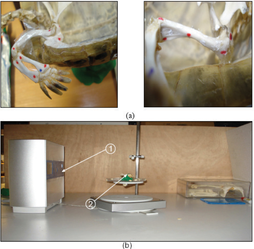
(a) Close up on the markers drawn on the bones (b) 1 - 3D scanner used to digitalize the limbs, 2 - Scanned limb
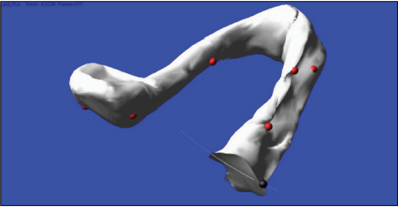
Scheme of the reconstructed bones and the coloured markers [18]
3. The virtual robot TATOR II
3.1 The virtual robot
From the data collected during the in vitro experiments, a virtual tortoise-like robot is created using the ADAMSView platform. TATOR II copies the kinematics and inertial properties of subject III. It is a linkage of 15 rigid bodies articulated by 22 degrees of freedom; it copies the mechanical design of subject III and the motion of subject I. The model consists of the shell imported from a 3D mechanical CAD program and four legs, as shown in Figure-9. Each spherical joint is replaced by a kinematic equivalent compound consisting of three revolute joints that have concurrent and orthogonal axes.

Different views of Tator-II a tortoise like virtual robot. 1-Head, 2 Scapula, 3-Humerus, 4-Radius, 5-Foreclaw, 6-Femur, 7-Tibia, 8 Hind claw and 9-Shell
3.2 Contact model
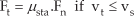
The friction and contact properties of the unilateral joint formed between each foot and the ground are modelled using the nonlinear compliant contact model in ADAMS, in which the normal contact force is evaluated with:

where n is an exponential coefficient and b is a cubic function of the penetration x [19]. Coulomb friction is used to model the tangential contact force expressed as:

Where:
vt: slip velocity at a contact point,
vs: is the stiction transition velocity
vd: is the friction transition velocity
In this study, the contact between each leg and the ground is considered punctual. The static coefficient of friction is measured as in previous studies [12]. To measure the dynamic coefficient of friction, the video and force measurements are used to identify the friction between the legs and the ground; the dynamic coefficient of friction is calculated as the mean ratio between the lateral and vertical components of the ground reaction forces on each limb [15]. μdyn = 0.14 and μstat = 0.3 are used in the simulations.
3.3 Control of TATOR II
Using the recordings of the contact forces and the motion, the Cartesian trajectories of the important anatomical points (joints' centres, metallic markers and claw contacts) are measured during a gait cycle of the right limbs. The acquisition of these points' trajectories is done frame by frame using custom software programmed using MATLAB. An automatic acquisition is not possible due to the quality of the X-ray films and the use of a video camera to film the motion of subject I in the lateral plane. To solve the inverse kinematics problem, two models for the right limbs are built using the ADAMS platform [15]. Figures 10 and 11 show these models.

Model of the right hind limb used to solve the inverse kinematics problem, it is composed of: 1-Shell, 2-Femur, 3-Tibia, 4-Hind claw and 5-Intermediate bodies.

Model of the right forelimb used to solve the inverse kinematics problem, it is composed of: 1-Shell, 2-Scapula, 3-Humerus, 4-Radius, 5- Fore claw and 6-Intermediate bodies

Joint angles during a gait cycle of limbs
In both models the shell is created using the attached markers on subject I during the in vivo experiments. The markers, the intermediate bodies and the claw contact point with the ground are animated using the Cartesian trajectories of special anatomical points during a gait cycle of each limb measured during the in vivo experiments. Intermediate bodies are used because tracking all the measured Cartesian trajectories is not possible due to the errors in measurements. The joint angles are recorded and then interpolated using Fourier series. Figure-12 shows the interpolated joint angles for the hind and fore limb respectively during a gait cycle.
Two of the scapula-humerus spherical joint angles are related by a simple linear equation:

and the third joint angle q8 is approximately constant (see Figure-13). The interpolated joint angles are used to control TATOR II using a PD control law and to simulate its motion.
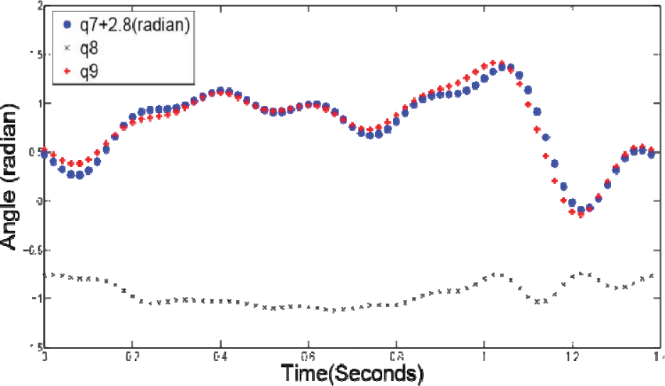
Synergy between q7 and q9 two joint angles of the shell-scapula joint articulation
Figure-14 and 15 show the motion of TATOR-II and subject I for the crawl posture, a good match is achieved in copying the motion of subject I to TATOR II.
Equally spaced simulation frames of TATOR II in Crawl posture for a period T=1.38s

Equally spaced video frames of subject I in motion for a period T=1.38s
3.4 Simulation of Quadruped Gaits
The motion of TATOR II is simulated for different gaits and the distance travelled by the centre of mass is recorded. This is achieved by changing the phase between the legs [20], [21]. Table-4 shows the distance travelled by the centre of mass during a cycle of the right forelimb for different gaits. The distance travelled by the centre of mass reaches its maximum value when the motion of TATOR II is simulated for the trot and canter gaits.
Distance travelled by the centre of mass for different gaits during a locomotion cycle

Result II: the solution of the inverse kinematics problem shows that two of the three joint angles of the scapulahumerus spherical articulation are related by a linear relation and the third is constant. A virtual model for a tortoise-like robot is built and simulated using the ADAMS-View environment.
4. Conclusion
This paper describes methods and experimental protocols to model, control and simulate a virtual tortoise-like quadruped robot.
This study brings many contributions to the field of biomimetic and quadruped robot research, in particular:
An approach to model the kinematics and to estimate the motion of tortoises. A dynamic model of bio-mimetically inspired virtual robot from the real animal for simulation and control. Significant experimental results on tortoise locomotion.
The experiments show that both living subjects use The hind limbs to accelerate and the forelimbs to decelerate (result I); a synergy between two joint angles of the scapula-humerus articulation is also noticed (result II). Many experiments are still to be conducted on large specimens to verify if other tortoises have these similarities. Several improvements to the virtual robot TATOR II are still to be investigated. In particular, a future perspective is to use the measured contact forces and joint angles to control the robot using a hybrid force/position law [22] and to build a physical prototype.