
Abstract
The flexible space manipulator is a highly nonlinear and coupled dynamic system. This paper proposes a novel composite sliding mode control to deal with the vibration suppression and trajectory tracking of a free-floating space rigid-flexible coupling manipulator with a rigid payload. First, the dynamic equations of this system are established by using Lagrange and assumed mode methods and in the meantime this dynamic modelling allows consideration of the modelling errors, the external disturbance and the vibration damping of a flexible link. Then, in modal space, the problems of the manipulator system's trajectory tracking and the vibration suppression are discussed by using the composite control approach, which combines a non-singular terminal sliding mode control (NTSMC) with an active vibration suppression control (AVSC). The NTSMC uses a fuzzy logic output instead of the symbol item, which smoothes the control signal, thereby inhibiting the chattering of the sliding mode control. Compared with common sliding mode control (SMC), the approach not only can reduce the chattering of the sliding mode control, but also can eliminate the singular phenomenon of the system's control input. In addition, it can assure the trajectory tracking and the vibration suppression. Many space missions can benefit from this modelling system, such as autonomous docking of satellites, rescuing and satellite servicing. Finally, the numerical simulations were carried out, which confirmed the effectiveness of these methods.
Keywords
1. Introduction
With the rapid development of space technology, there has been great interest in the design and control of space manipulators with flexible links and bases. These have a number of advantages: light weight, small driving force and low energy consumption etc. However, the structural flexibility inevitably causes elastic deflection and vibration. So the control problem for flexible manipulators is much more complex than the equivalent one for rigid manipulators. A flexible manipulator controller not only must achieve the same motion objectives as a rigid manipulator, but also must stabilize the vibration that is naturally excited. Furthermore, a primary problem concerns the motion coordination between the spacecraft and the manipulator. In fact, due to the lack of a stationary base, the free-floating spacecraft will react to the motions of the attached manipulator. If the inertia of the manipulator, with respect to that of the spacecraft, is non-negligible, the application of conventional control techniques for a ground-fixed manipulator becomes unfeasible and different strategies have to be pursued. A flexible space manipulator is a highly nonlinear and coupled dynamic system. Many techniques in dynamic modelling of space robots have been developed [1, 2, 3]. The assumed mode method to describe the elastic deformation has been used in [4] and the dynamic model of a flexible dual-arm space robot is built by the Lagrange approach. The problem of the dynamics and control of a flexible space robot capturing a static target was presented in [5]. The dynamic model of the robot system is derived with Lagrangian formulation. In [6] the problem of the generalized contact forces between the space robot end-effecter and the target satellite as internal holonomic and nonholonomic constrains has been considered. Nowadays, many researchers have concentrated on developing control strategies for design and implementation in various applications of flexible manipulators. In several pieces of work [7, 8, 9] neural network based control schemes have been proposed to obtain controllers with adaptation capabilities for the uncertainties for space manipulators. Classical adaptive control schemes have been proposed [10, 11] and other control schemes, like robust control [12, 13, 14] and namely intelligent control [15], can be found. Variable structure control with a sliding mode is a powerful robust nonlinear control technique that has been intensively developed during the last 35 years [16, 17]. The term “variable structure system” (VSS) first made its appearance in the late 1950s. Since that time, the first expectations of such systems have naturally been re-evaluated and their real potential has been revealed. Novel research directions have originated due to the appearance of novel classes of control problems, novel mathematical methods and novel control principles. The sliding mode design approach usually consists of two steps [18, 19]. First, the switching surface is designed such that the system motion in sliding mode satisfies design specifications. Second, a control function is designed making the switching surface attractive to the system state. In some work [20, 21], the non-singular terminal sliding mode controllers have been proposed for flexible and rigid manipulators, respectively. A novel design approach of a multiple input multiple output adaptive fuzzy terminal sliding-mode controller for robotic manipulators is described in [22], which does not require detailed system parameters for the presented controller. In [23] a robust control approach is developed to control a robot in the task space using a sliding mode by support of feedback linearization control and a back-stepping method. [24] proposed a PID integral variable structure regulation controller for robot manipulators.
In this paper a novel composite sliding mode control approach for a free-floating space rigid-flexible coupling manipulator with a rigid payload are proposed. The dynamic model of the manipulator is established by considering the modelling errors, the external disturbance and the vibration damping of a flexible link, based on Lagrange and assumed mode methods, as well as conservation of momentum theorem. The composite control approach combines NTSMC with AVSC for trajectory tracking and vibration suppression. The general sliding mode control inevitably causes chattering and may cause a singular phenomenon. Compared with the SMC, the novel NTSMC with the fuzzy logic inference can inhibit the chattering of the sliding mode control, at the same time the singular phenomenon can be eliminated for the system's control input. Finally, numerical simulations are performed to demonstrate the effectiveness of the proposed methods.
2. Dynamic model description for the manipulator system
In this section we introduce the dynamic model of a free-floating space rigid-flexible coupling manipulator with three links. It includes a base, three links and a rigid payload. Among them, L1 and L2 are rigid links and L3 is a flexible link. Let Xc=[xc yc θ] T be the pose of the payload, Xb = [xb yb θ b ] T be the pose of the base, θ c is the attitude angle of the base and θ b is the attitude angle of the base. The coordinate systems in Fig.1 are defined as follows:

An articulated three-link rigid-flexible coupling space manipulator; ∊-OXY—The inertial coordinate system. ∊o-ObXbYb—The base coordinate system. ∊i-OiXiYi—The fixed in the ith link coordinate system. ∊c-OcXcYc—The payload coordinate system fixed to the centre of mass of the payload.
The link coordinate system is established in accordance with Denavit-Hartenberg rules. The elastic deformation mode is described as ω(x3,t) by the assumed mode method:
where n is the mode's order(n = 2), e˜ i (t) is the flexible link's generalized deformation variable and x3 is the X3 direction coordinate in the coordinate system of the flexible link.
The total momentum of the system is given by:
where
Moreover, the total potential energy of the system is given by:
where Ui(i = 1,2) is the potential energy of the rigid links Li (i = 1,2). As the system is in micro-gravity space, the gravitational potential energy can be ignored. The potential energy of the system is only generated by the elastic deformation of the flexible-link. Then U1=0,U2=0.
The flexible link's potential energy can be written as:

where EI is the module of elasticity.
According to Eq. (2) and Eq. (3), the Lagrange function is given by:

Based on the principle of D'Alembert-Lagrange, the Lagrange equations are given by:

where τ i is the joint torque, J ∊ R3×3 is the manipulator's Jacobian matrix and F ∊ R3×1 is the force vector exerted by the end-effector on the payload at the grasp point.
According to Eq. (6), the dynamic equations of the system are given by:


where Mij (i = 1,2, j = 1,2,3) are the generalized mass matrices, Dij (i=1,2, j = 1,2,3) are the damp matrices, K is the stiffness matrix of the flexible links and Q = [e˜1 e˜2] T = [Q1 Q2] T is the generalized deformation variable. θ= [θ1 θ2 θ3]T is the joint angle vector of the links and τ = [τ1 τ2 τ3]T is the joint torque vector.
According to the Newton-Euler formula, dynamic equations of the payload are given by:


where mc is the mass of the payload, Ic is the inertia moment of the payload, fo is the resultant force between the end-effector and the payload and No is the resultant moment between the end-effector and payload. rc is the position vector of the payload centre with respect to the inertial coordinate system.
According to Eq. (9) and Eq. (10), the dynamic equation of the payload can be written as:

where
The end-effector force F can be expressed as:

The relationship between Ẋc, Ẋb and

where Jcb is the Jacobian matrix for the payload with respect to the base and Jcq is the Jacobian matrix for the payload with respect to the joint.
We assume the space manipulator system is operated in free-floating mode, so that linear and angular momenta are conserved. On the assumption that total linear and angular momenta are zero, so we can obtain:


where Hi (i = 1…5), Ni(i = 1…5), Ac, Bc, Cc, Dc, Ec are the coefficient matrices, respectively. Eq. (16) is the dynamic equation of the system.
In the actual modelling process there are measurement errors of model parameters and the joint friction, as well as other factors of uncertainty, which lead to a systematic modelling error. The system in practice will be subjected to a variety of external disturbances, so Eq. (14) and Eq. (15) can be rewritten as:


where d1 is the model error for the system, d2 is the external disturbance and d3 is the vibration damping of the flexible link.
According to Eq. (17) and Eq. (18), the dynamic Equation (16) can be modified to:

3. Sliding mode control for the manipulator system
In this section the controller for robotic manipulators combines the advantages of the non-singular terminal sliding mode control and the fuzzy inference mechanism.
Eq. (19) can be written as the following state equation:

It is assumed that f1 = F̂ 1 + Δf, where F̂1 is an estimated value of f1, Δf is the model uncertainty with modelling error and the external disturbance and |Δf|≤ α, α is a positive constant defined as the upper boundary of Δf. Let's define the tracking error:

where x1d = Xdc is the desired payload's position.
3.1 SMC law
To obtain the finite time convergence of the system tracking error, the sliding surface is defined as:

whereK1 = diag(λ1, λ2, λ3), in which λ i (i = 1,2,3) is a positive constant.
The SMC(22) derivative along the state Eq. (20) of the system dynamics is:

The controller can then be expressed as:

where sgn(s) is the sign function of s, i.e., sgn(s) = 1 if s>0; sgn(s) = 0 if s=0; sgn(s) =-1 if s<0. The switching gain Ks is a positive constant and Ks ≥ α.
Substituting Eq. (22) into Eq. (23) yields:

Obviously, s⋅≤0 Under the action of the controller u1, the sliding mode is subsistent and accessible.
3.2 NTSMC law
To obtain the finite time convergence of the system tracking error, the sliding surface is defined as:

where Ke =diag(λ1,λ2,λ3), in which λi = 1,2,3) is a positive constant, Mare odd numbers and
The NTSMC(26) derivative along the state Eq. (20) of the system dynamics is:
So, the controller can be expressed as:
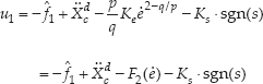
where Ks is a switching gain and

The derivative of the Lyapunov function, with respect to time, is obtained as:

where Ks is a switching gain and Ks ≥ α.
Thus V̇ ≤ 0for all t and the system is stable and the system's state errors will converge to zero in a finite time.
The NTSMC not only can guarantee the system states reach a terminal sliding surface in a finite time, but also can eliminate the singular phenomenon for the system.
3.3 Jitter suppression and force control of the manipulator system
When s = 0, switching will bring about jitter. For jitter suppression, a saturation function sat(s/δ) can be used, instead of the sign function sgn(s).
In this section, fuzzy inference rules are used to adjust the fuzzy quantization factor of the switching function. On the one hand it can guarantee the stability of the entire system, on the other hand it ensures that the system has good transient performance. We set:

According to Eq. (30),
First, we select positive constant β and normalize s, assuming ŝ = βs, and define ŝ as the input variable of the fuzzy system and Δu as the output variable of the fuzzy system.
Second, both ŝ and Δu are partitioned into seven fuzzy subsets: negative big (NB), negative middle(NM), negative small(NS), zero (ZE), positive small(PS), positive middle(PM) and positive big (PB). The triangular shape membership function of ŝ is shown in Fig. 2. The singleton membership function of Δu is shown in Fig. 3.
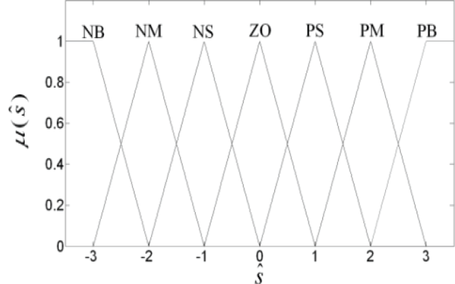
Input membership function
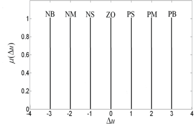
Output membership function
According to Fig. 2 and Fig. 3, the fuzzy rules can be determined as follows:

Choosing the weighted average defuzzification, the output of the fuzzy inference system can be written as:
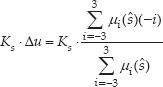
where μ i (ŝ)is the strength of the ith rule and (-i) is the associated single membership function of Δu.
According to u1 = Ak−1(τ – JTFg), we define the controller as τ:

where τ g is defined as:
where eF=Fg – Fgd, Fgd is the desired value of Fg and the gain matrix KI is chosen as the diagonal and positive elements.
4. AVSC for the manipulator system
In the modal space, a modal control force Fm is used to suppress the vibration of the flexible link.
According to Eq. (18), the vibration equation becomes:

where C = N2−1 N4 is the generalized damping matrix, K = N2−1N5 is the generalized stiffness matrix and f2=-N2−1(N1ẍc+N3Ẋc+d3) is the modal excitation force.
The modal control force Fm =[Fm1 F2] T is introduced to the system, so Eq. (32) becomes:

Setting x = [Q Q̇]T, u2 = f2 + Fm. Eq. (35) becomes:

A quadratic performance index J* is defined as:

where W is a positive-definite matrix and R is a positive matrix. The control objective is to design the optimal control law u2 that minimizes the performance index J*.
Then, the optimal control input u2(t) can be derived as:
where matrix P̄ is the unique positive symmetric solution to the Riccati equation and denotes:

According to Eq. (35), the modal control force Fm is given by:

where f˜2 is the estimate of f2. It is assumed that f˜2=Ñ2−1(Ñ1ẍc+Ñ3Ẋc),Ñ1,Ñ2,Ñ3 are the estimates of N1,N2,N3. Eq. (40) becomes:

The proposed method, which combines NTSMC with the modal force control, can guarantee the trajectory tracking and the vibration suppression.
According to Eq. (17), Eq. (18) and Eq. (35), the dynamic Eq. (19) can be written as:

Let's define the composite controller as τ:

The architecture of the composite control for the free-floating space rigid-flexible coupling manipulator system is shown in Fig. 4.
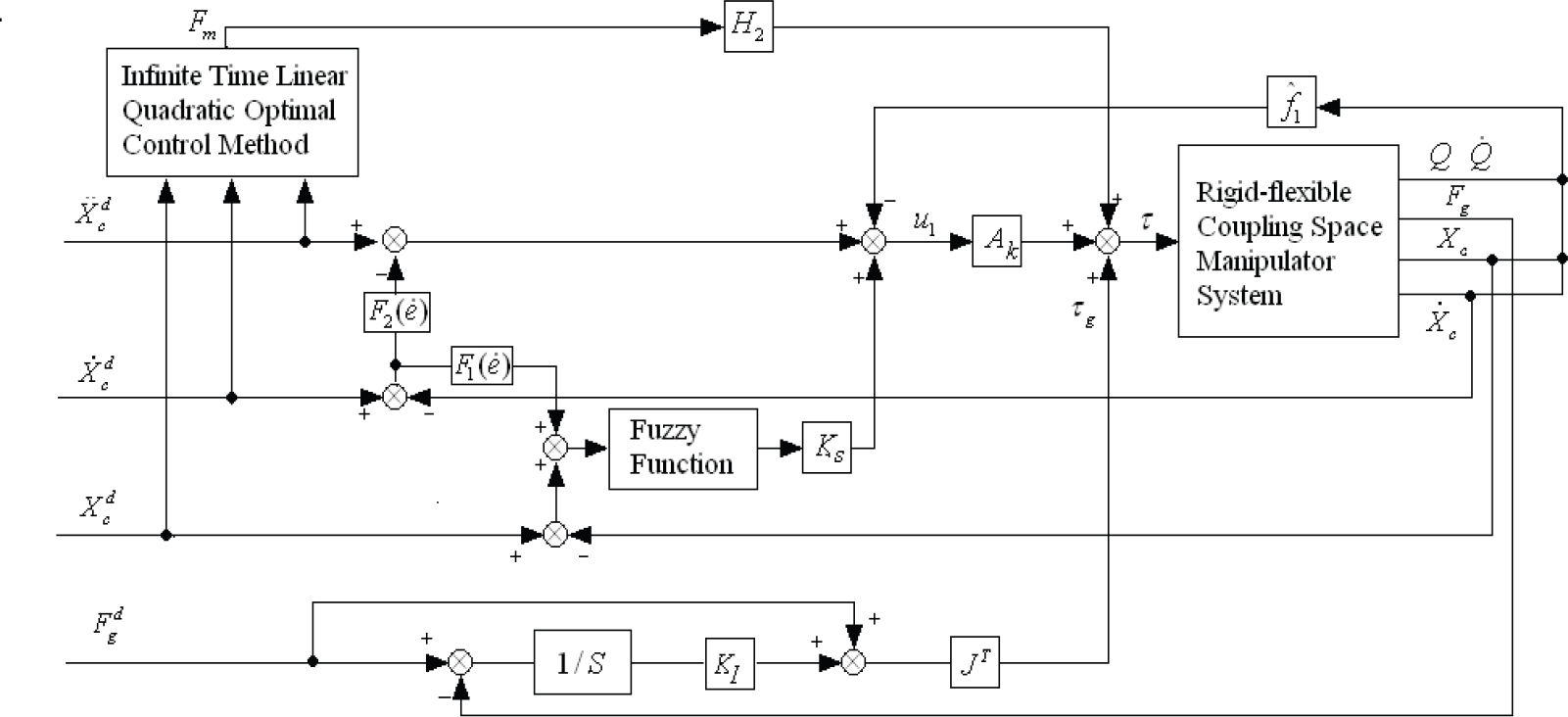
The architecture of the composite control for the free-floating space rigid-flexible coupling manipulator system
5. Simulation results
In this section, to illustrate the effectiveness of the proposed strategy, the numerical simulations have been performed via Matlab with SIMULINK. The parameters of the system are given in Table 1.
The parameters of the free-floating space rigid-flexible coupling manipulator system

The original pose of the base is set to Xb = [1.5m 0m 0rad]
T
. The desired grasping force/moment is chosen as Fgd = \10N,0N,0N· m]
T
. The model errors and disturbances d1,d2,d3 are assumed as
Let
The desired trajectories for the payload are given by:

For the purpose of comparison, the simulations have been carried out by considering SMC and NTSMC for the control of the manipulator system in this work. The first is the classical SMC that shows the simulation results in Fig. 5–7. Fig. 8–10 show the simulation results under the controller NTSMC. Fig. 5 and 8 show the position curves of the base, with SMC and NTSMC, respectively. Fig. 6 and 9 denote the position tracking curves of the payload with SMC and NTSMC, respectively. Fig. 7 and 10 show the position tracking error curves of the payload with SMC and NTSMC, respectively. The simulation results show that the speed of the tracking error's convergence to zero for the NTSMC is faster.
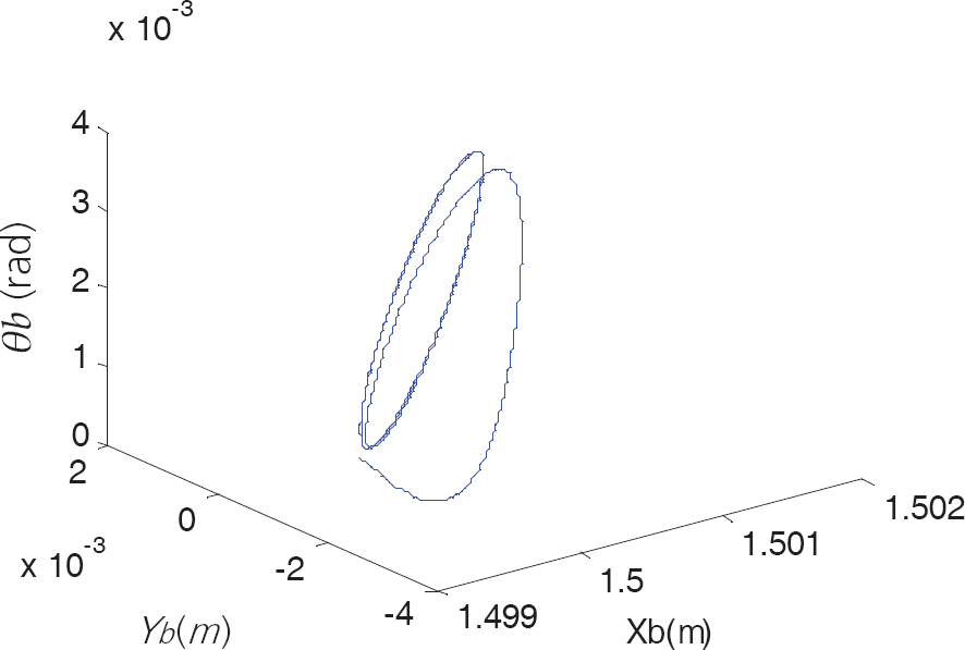
The position curves of the base with SMC

The position tracking curves of the payload with SMC

The position tracking error curves of the payload with SMC

The position curves of the base with NTSMC

The position tracking curves of the payload with NTSMC
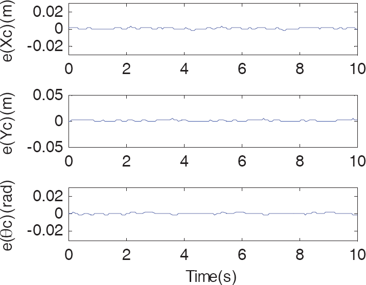
The position tracking error curves of the payload with NTSMC
Fig.11 shows the change curve of the modal force. Fig. 12 shows the change curve of the generalized coordinates of the flexible link. Fig. 13 shows the change curve of the grasping force between the end-effector and the payload. The above composite control scheme can track the expected trajectory accurately, even though there is uncertainty in the model parameters. The simulation results clearly illustrate that the tracking effect of the grasping force and the vibration suppression are very good.

The change curves of the modal force

Generalized coordinates of the flexible link
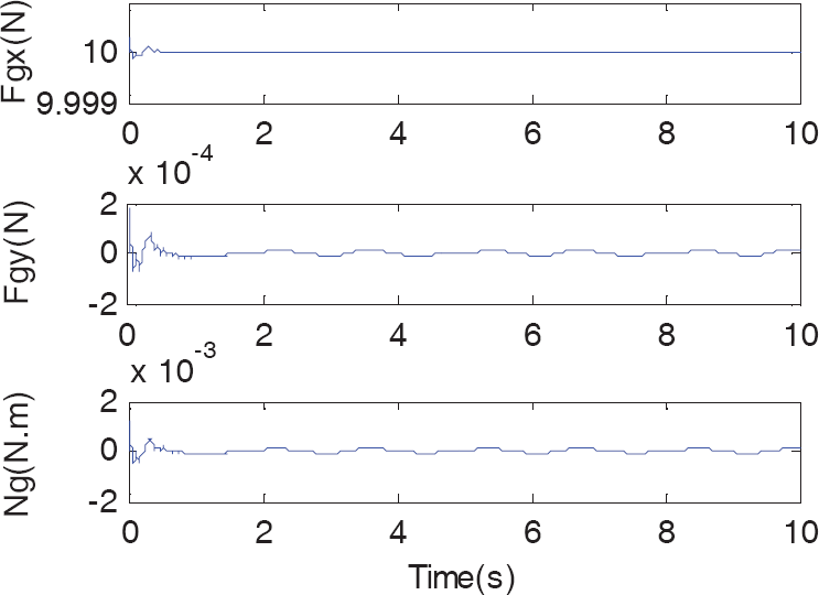
The change curves of the grasping force between end-effector and the payload.
6. Conclusions
The dynamic model is established by using an assumed mode method combined with Lagrange and momentum conservation theorem, while considering the modelling errors, external disturbance and vibration damping of the flexible link. Based on this model, SMC and NTSMC are designed to ensure the trajectory tracking control of the rigid payload, respectively. In the NTSMC controller, the fuzzy output is used, instead of the symbol item, to smooth the control signal, thereby the chattering of the sliding mode control has been inhibited. The NTSMC not only can guarantee the system states reach the terminal sliding surface faster, but also can eliminate the singular phenomenon for the system's control input. The modal force control is presented to suppress the flexible vibration, which is solved by using an infinite time linear quadratic optimal control method. The computer simulations have been performed to validate the effectiveness of the proposed controller, which demonstrate the proposed controller not only can assure the trajectory tracking, but also can suppress the flexible vibration and control the grasping force between the end-effector and the payload.
Footnotes
7. Acknowledgments
This work was supported by the Foundation of Manufacturing Systems Engineering State Key Laboratory, Xi'an Jiaotong University of China (No. 201002).